
Underwater Repair of Concrete Elements with TRC Grouting System

Abstract
:1. Introduction
2. Material Tests
2.1. Materials
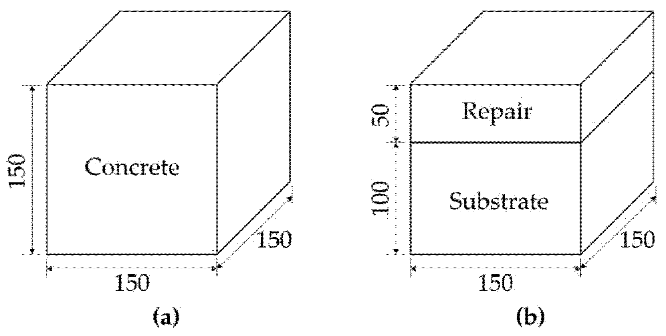
2.2. Test Specimens
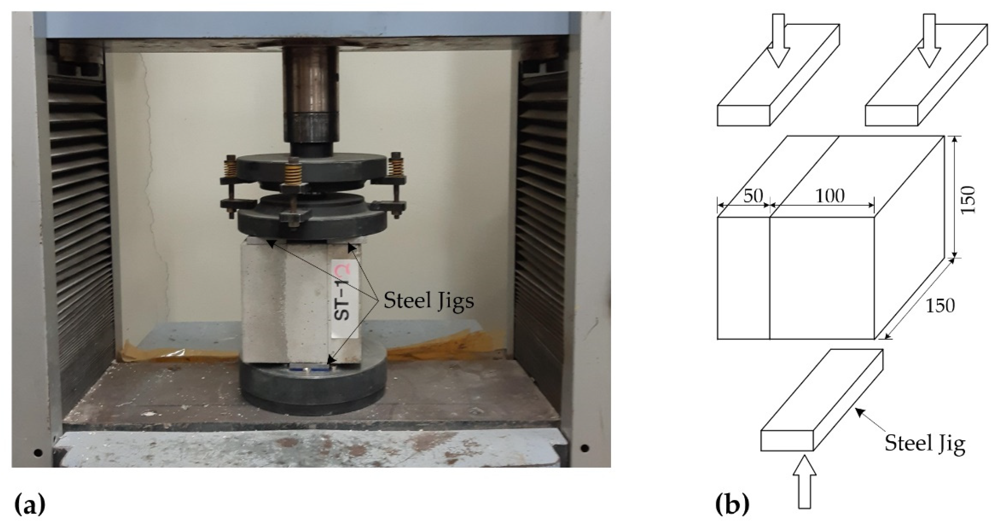
2.3. Results of Bond Strength Tests
3. Structural Test for RC Slabs Repaired with TRC Grouting System
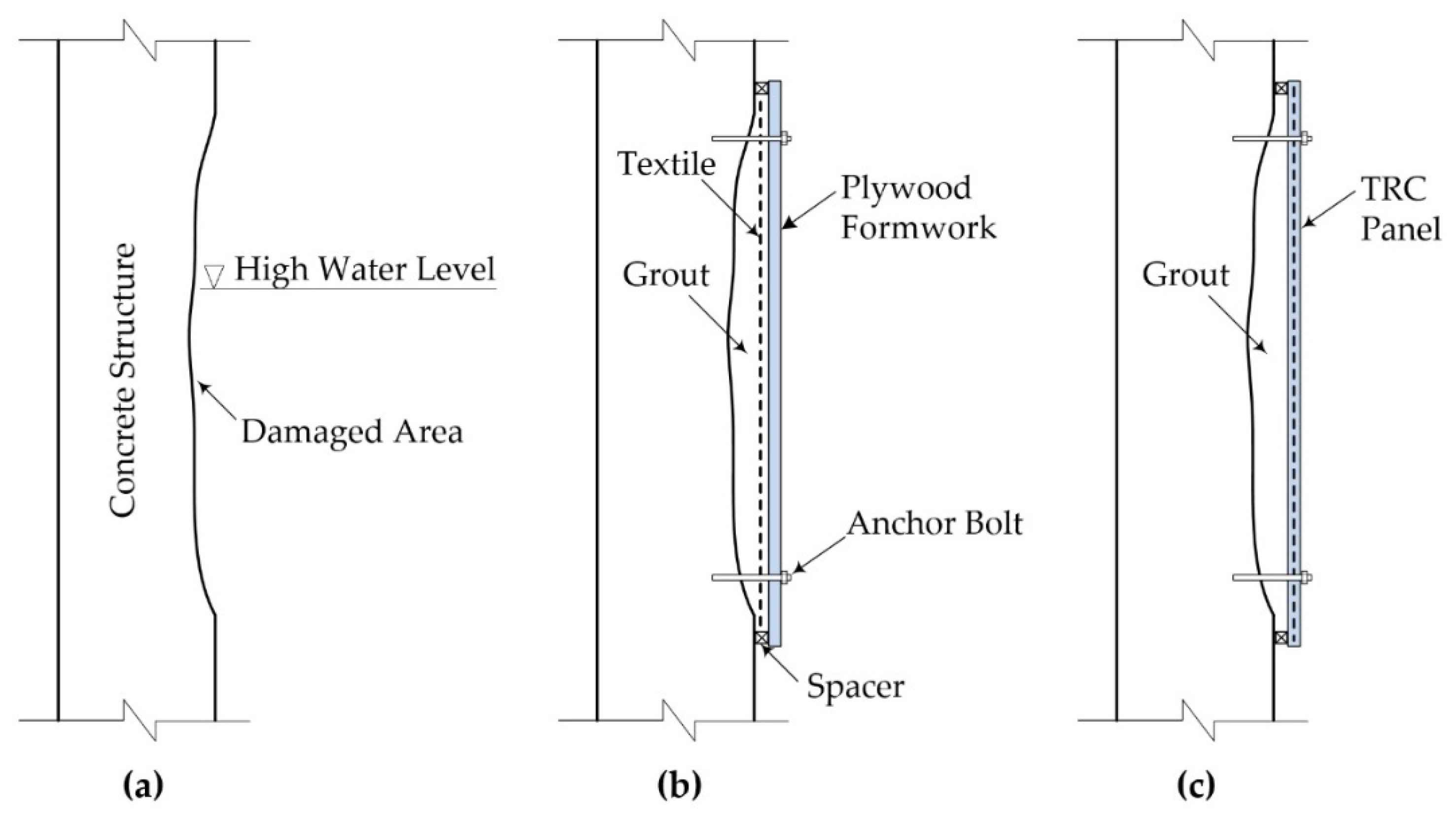
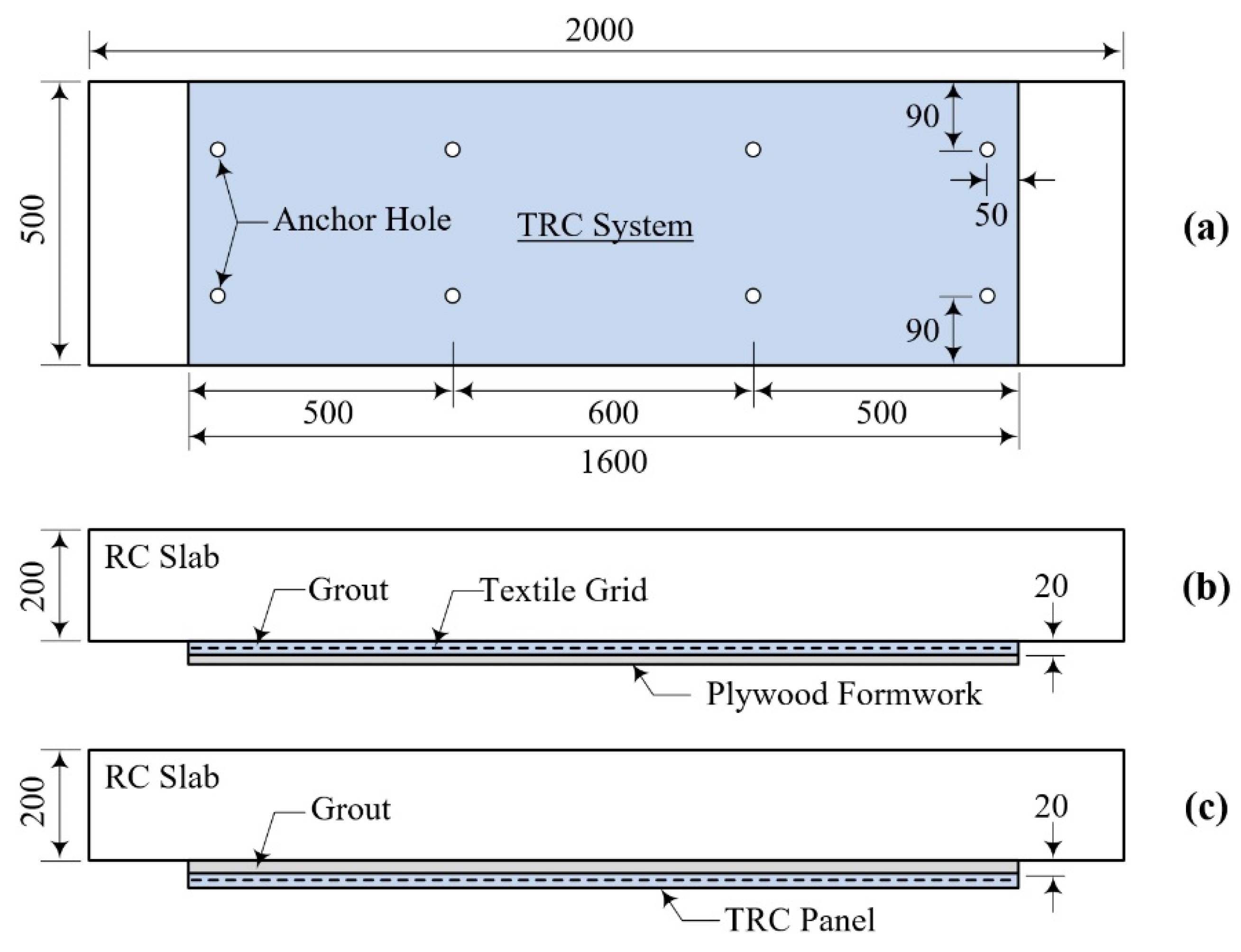
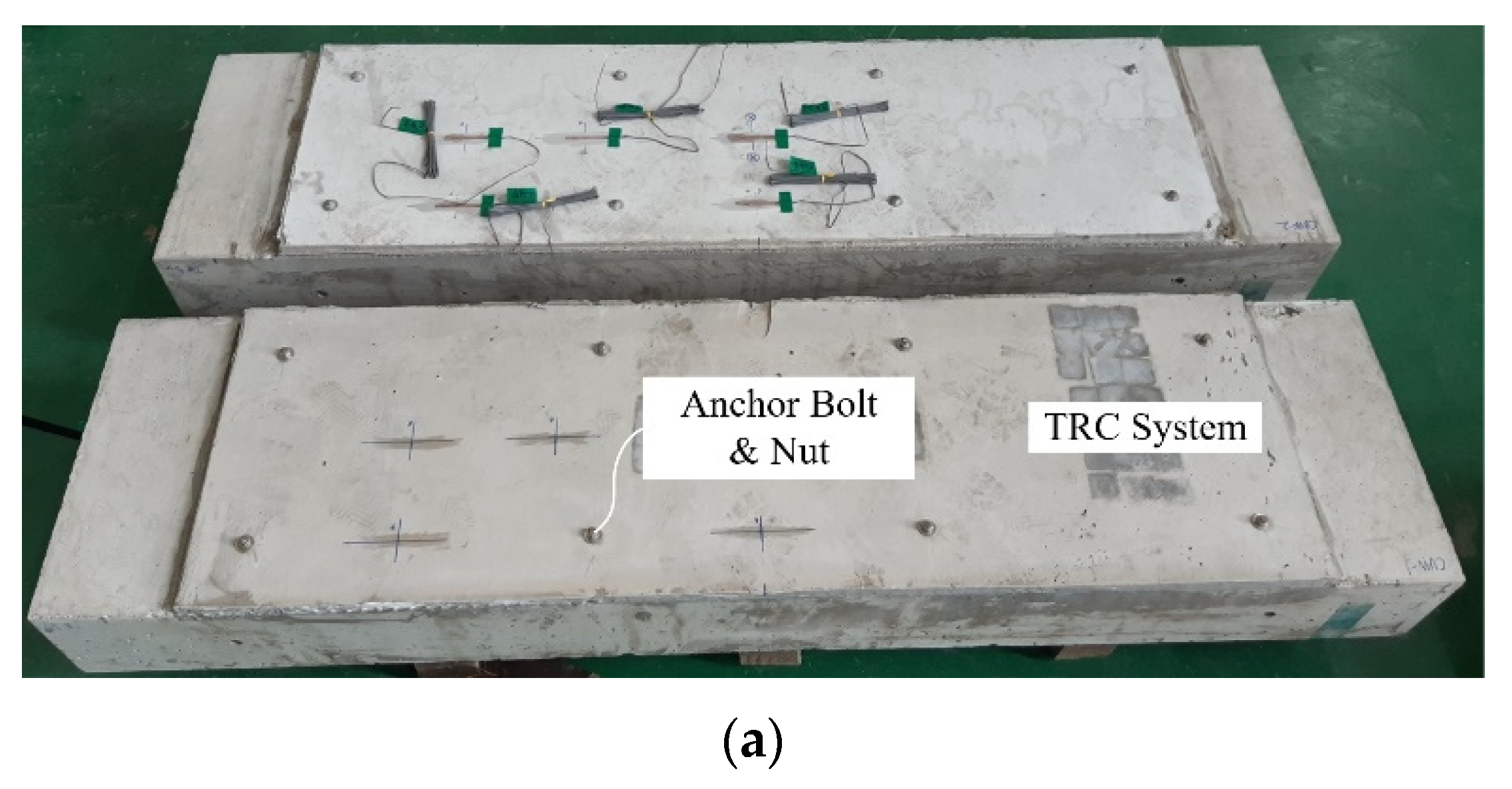
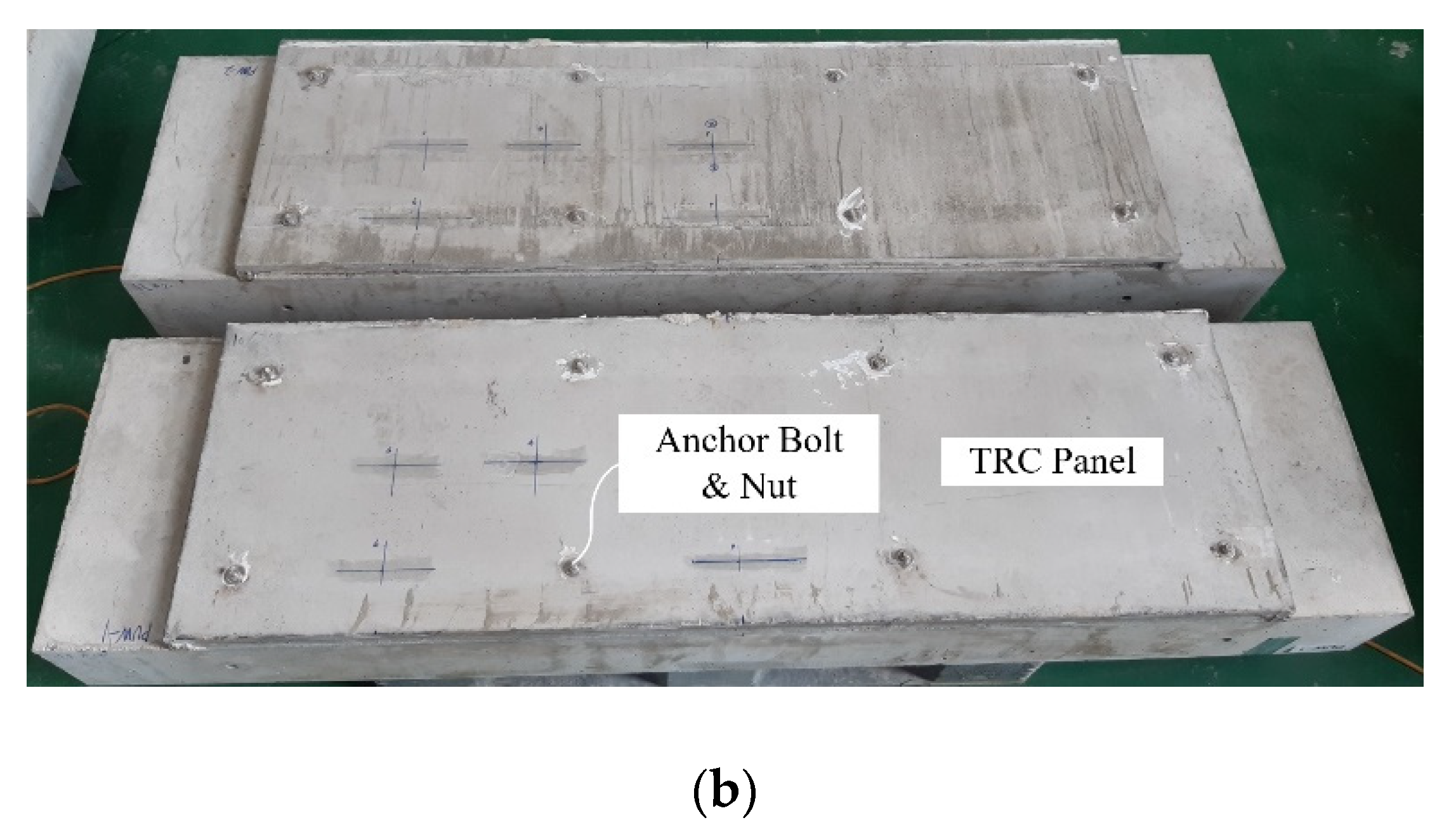
3.1. TRC Grouting System for Damaged Concrete Structures
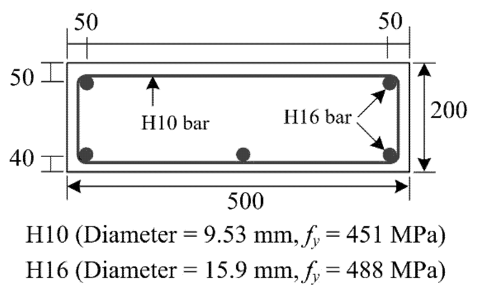
3.2. Fabrication of Full-Scale RC Specimens
3.3. RC Slabs Repaired with TRC Grouting System
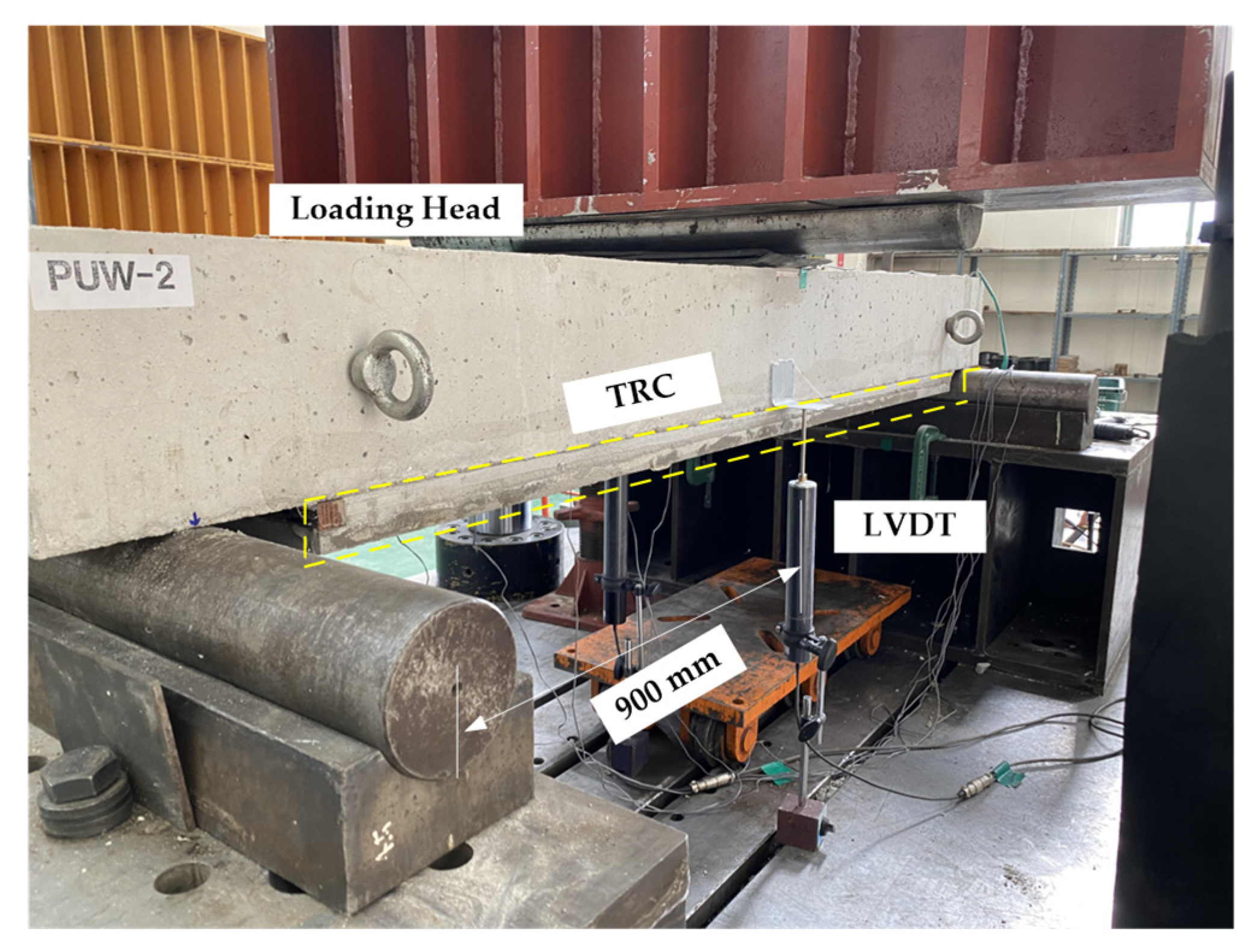
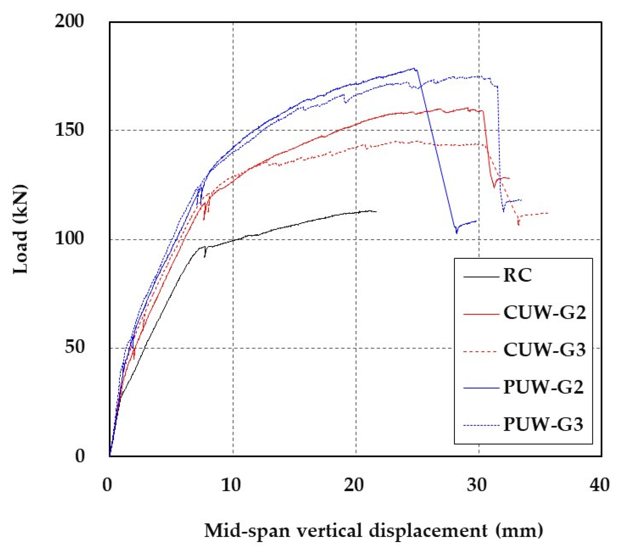
3.4. Load-Displacement Behavior of RC Slab Repaired with TRC Grouting System
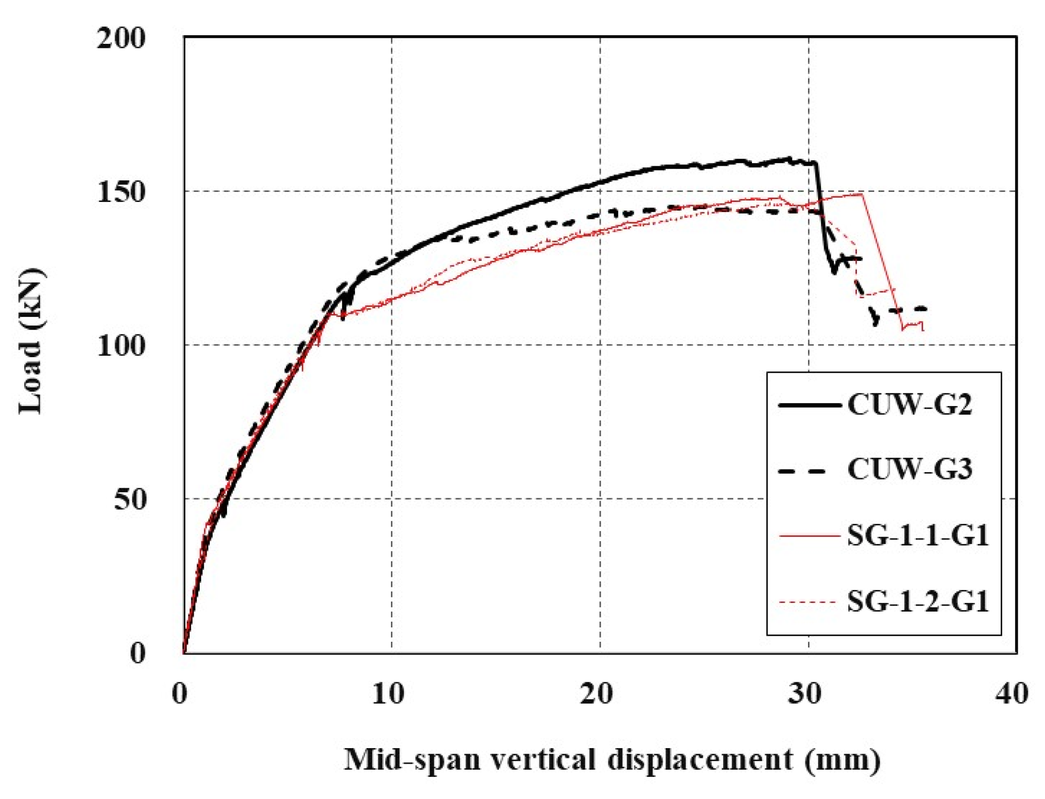
3.5. Effect of Type of Grouting Material
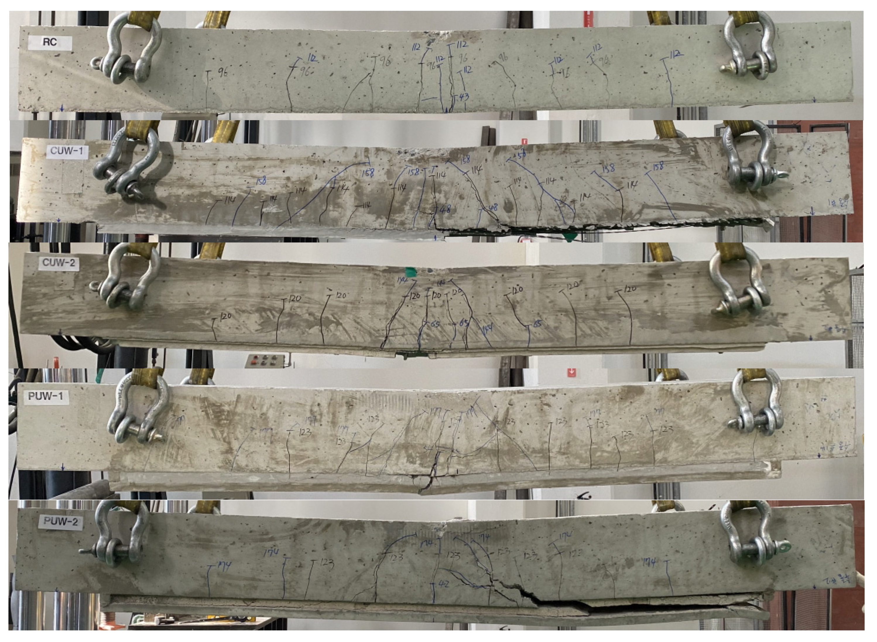
3.6. Crack Pattern and Failure Mode
4. Conclusions
Author Contributions
Funding
Institutional Review Board Statement
Informed Consent Statement
Data Availability Statement
Conflicts of Interest
References
- ACI Committee 546. Guide to Underwater Repair of Concrete; ACI Report 546.2R-98; American Concrete Institute: Farmington Hills, MI, USA, 1998. [Google Scholar]
- Khayat, K.H. Underwater Repair of Concrete Damaged by Abrasion-Erosion; Technical Report REMR-CS-37; US Army Corps of Engineers: Washington DC, USA, 1991.
- Müllera, H.S.; Bohnera, E.; Vogela, M.; Kvitsela, V.; Solichinb. Innovative Solutions for the Construction and the Repair of Hydraulic Structures. Procedia Eng. 2013, 54, 22–38. [Google Scholar] [CrossRef] [Green Version]
- Fitch, G.M. Minimizing the Impact on Water Quality of Placing Grout Underwagter to Repair Bridge Scour Damage; Final Report VTRC 03-R16; Virginia Transportation Research Council: Charlottesville, VA, USA, 2003.
- Sen, R.; Mullins, G. Application of FRP composites for underwater piles repair. Composites Part B 2007, 38, 751–758. [Google Scholar] [CrossRef]
- Karagah, H.; Dawood, M.; Belarbi, A. Experimental Study of Full-Scale Corroded Steel Bridge Piles Repaired Underwater with Grout-Filled Fiber-Reinforced Polymer Jackets. J. Compos. Constr. 2018, 22, 04018008. [Google Scholar] [CrossRef]
- Mohammed, A.A.; Manalo, A.C.; Ferdous, W.; Zhuge, Y.; Vijay, P.V.; Alkinani, A.Q. State-of-the-art of prefabricated FRP composite jackets for structural repair. Engin. Sci. Tech. Int. J. 2020, 23, 1244–1258. [Google Scholar] [CrossRef]
- Koutas, L.M.; Tetta, Z.; Bournas, D.A.; Triantafillou, T.C. Strengthening of concrete structures with textile reinforced mortars: State-of-the-art review. J. Compos. Constr. 2019, 23, 03118001. [Google Scholar] [CrossRef]
- Giese, A.C.H.; Giese, D.N.; Dutra, V.F.P.; Da Silva Filho, L.C.P. Flexural behavior of reinforced concrete beams strengthened with textile reinforced mortar. J. Build. Eng. 2021, 33, 101873. [Google Scholar] [CrossRef]
- Alatawna, A.; Nahum, L.; Sripada, R.; Birenboim, M.; Regev, O.; Peled, A. Textile-reinforced mortar: Durability in salty environment. Cem. Conc. Compos. 2022, 130, 104534. [Google Scholar] [CrossRef]
- Guo, L.; Deng, M.; Chen, H.; Li, R.; Ma, X.; Zhang, Y. Experimental study on pre-damaged RC beams shear-strengthened with textile-reinforced mortar (TRM). Engin. Struct. 2022, 256, 113956. [Google Scholar] [CrossRef]
- Ebead, U.; Shrestha, K.C.; Afzal, M.S.; El Refai, A.; Nanni, A. Effectiveness of Fabric-Reinforced Cementitious Matrix in Strengthening Reinforced Concrete Beams. J. Compos. Constr. 2017, 21, 04016084. [Google Scholar] [CrossRef]
- Koutas, L.; Bournas, D.A. Flexural Strengthening of Two-Way RC Slabs with Textile-Reinforced Mortar: Experimental Investigation and Design Equations. J. Compos. Constr. 2017, 21, 04016065. [Google Scholar] [CrossRef]
- Scheerer, S.; Zobel, R.; Müller, E.; Senckpiel-Peters, T.; Schmidt, A.; Curbach, M. Flexural Strengthening of RC Structures with TRC—Experimental Observations, Design Approach and Application. Appl. Sci. 2019, 9, 1322. [Google Scholar] [CrossRef] [Green Version]
- Scholzen, A.; Chudoba, R.; Hegger, J. Thin-walled shell structures made of textile-reinforced concrete Part I: Structural design and construction. Struct. Concr. 2015, 16, 106–114. [Google Scholar] [CrossRef]
- May, S.; Steinbock, O.; Michler, H.; Curbach, M. Precast slab structures made of carbon reinforced concrete. In Structures; Elsevier: Amsterdam, The Netherlands, 2019; Volume 18, pp. 20–27. [Google Scholar]
- Gopinath, S.; Madheswaran, C.K.; Prabhakar, J.; Thivya Devi, K.G.; Lakshmi Anuhya, C. Strengthening of unreinforced brick masonry panel using cast-in-place and precast textile-reinforced concrete. J. Earthq. Eng. 2020, 26, 1209–1227. [Google Scholar] [CrossRef]
- Brameshuber, W. Textile Reinforced Concrete, State-of-the-Art Report of RILEM Technical Committee 201-TRC; RILEM Report 36; RILEM Publications: Bagneux, France, 2006. [Google Scholar]
- ACI Committee 549. Guide to Design and Construction of Externally Bonded Fabric-Reinforced Cementitious Matrix (FRCM) Systems for Repair and Strengthening Concrete and Masonry Structures; American Concrete Institute: Farmington Hills, MI, USA, 2013. [Google Scholar]
- Triantafillou, T. Textile Fibre Composites in Civil Engineering; Woodhead Publishing: Duxford, UK, 2016. [Google Scholar]
- Kim, H.-Y.; Koh, K.-T.; You, Y.-J.; Ryu, G.-S.; Seo, D.-W.; Jin, S.-S.; Ahn, G.-H.; Nam, J.-H. Load-deflection behaviour of concrete slab-type elements casted on stay-in-place TRC formwork. Compos. Struct. 2020, 244, 112310. [Google Scholar] [CrossRef]
- You, Y.-J.; Kim, H.-Y.; Ryu, G.-S.; Koh, K.-T.; Ahn, G.-H.; Kang, S.-H. Strengthening of Concrete Element with Precast Textile Reinforced Concrete Panel and Grouting Material. Materials 2020, 13, 3856. [Google Scholar] [CrossRef] [PubMed]
- Kim, H.-Y.; You, Y.-J.; Ryu, G.-S. Reinforced Concrete Slabs Strengthened with Lap-Spliced Carbon TRC System. Materials 2021, 14, 3340. [Google Scholar] [CrossRef] [PubMed]
- ASTM C150/C150M-20; Standard Specification for Portland Cement. ASTM International: West Conshohocken, PA, USA, 2020.
- Kim, H.-Y.; You, Y.-J.; Ryu, G.-S. Flexural Strengthening of RC Slabs with Lap-Spliced Carbon Textile Grids and Cementitious Grout. Materials 2022, 15, 2849. [Google Scholar] [CrossRef] [PubMed]
- Momayez, A.; Ehsani, M.R.; Ramezanianpour, A.A.; Rajaie, H. Comparison of methods for evaluating bond strength between concrete substrate and repair materials. Cem. Conc. Res. 2005, 35, 748–757. [Google Scholar] [CrossRef]
- De la Varga, I.; Muñoz, J.F.; Bentz, D.P.; Spragg, R.P.; Stutzman, P.E.; Graybeal, B.A. Grout-concrete interface bond performance: Effect of interface moisture on the tensile bond strength and grout microstructure. Constr. Bldg. Mater. 2018, 170, 747–756. [Google Scholar] [CrossRef] [PubMed]
- Kim, H.-Y.; You, Y.-J.; Ryu, G.-S. Reinforced Concrete Slabs Strengthened with Carbon Textile Grid and Cementitious Grout. Materials 2021, 14, 5046. [Google Scholar] [CrossRef] [PubMed]


| Material | Cement 1 | Water | Fly Ash | GGBS 2 | Sand | Coarse Aggregate 3 | Super- Plasticizer | Design Strength (MPa) |
|---|---|---|---|---|---|---|---|---|
| Concrete | 263 | 167 | 56 | 56 | 828 | 934 | 2.63 | 27 |
| Mortar | 466 | 278 | - | 466 | 1024 | - | 3.00 | 30 |
| Grout ID | Grout Type | Design Strength (MPa) |
|---|---|---|
| G1 | Multi-purpose repair | 50 |
| G2 | Underwater repair | 50 |
| G3 | Underwater repair | 30 |
| Cement 1 | Sand | Water | Silica Fume | Super- Plasticizer | Expansion Agent | PVA Fibers 2 |
|---|---|---|---|---|---|---|
| 1055.0 | 1130.0 | 142.0 | 42.0 | 8.4 | 99.8 | 0.3% |
| Specimen ID | Specimen Type | Substrate Material | Repair Material | Interface | Casting Condition | No. of Specimen |
|---|---|---|---|---|---|---|
| STC | A | Concrete | - | - | Air | 3 |
| ST-1 | B | Concrete | G1 | Concrete–grout | Air | 3 |
| ST-2 | B | Concrete | G1 | Concrete–grout | Underwater | 3 |
| STU-1 | B | Concrete | G2 | Concrete–grout | Underwater | 3 |
| STU-2 | B | Concrete | G3 | Concrete–grout | Underwater | 3 |
| STP | B | Mortar | G1 | Mortar–grout | Underwater | 3 |
| STPU-1 | B | Mortar | G2 | Mortar–grout | Underwater | 3 |
| STPU-2 | B | Mortar | G3 | Mortar–grout | Underwater | 3 |
| Specimen ID | Substrate Type | Grout Type | Interface | Bond Strength (MPa) | STD (MPa) | COV (%) |
|---|---|---|---|---|---|---|
| STC | Concrete | - | - | 10.4 | 0.7 | 7.1 |
| ST-1 | Concrete | G1 | Concrete–grout | 1.5 1 | 0.2 | 14.3 |
| ST-2 | Concrete | G1 | Concrete–grout | 5.0 | 0.2 | 3.4 |
| STU-1 | Concrete | G2 | Concrete–grout | 9.4 1 | 2.0 | 21.2 |
| STU-2 | Concrete | G3 | Concrete–grout | 6.4 | 1.0 | 16.3 |
| STP | Mortar | G1 | Mortar–grout | 6.5 | 1.0 | 15.1 |
| STPU-1 | Mortar | G2 | Mortar–grout | 4.8 | 1.0 | 21.6 |
| STPU-2 | Mortar | G3 | Mortar–grout | 10.2 1 | 1.3 | 13.8 |
| Specimen ID | Repair Method | Grout Type | No. of Textile | Formwork Type | Thickness of Specimen (mm) | No. of Specimens |
|---|---|---|---|---|---|---|
| RC | - | - | - | - | 200 | 1 |
| CUW-G2 | CIP TRC | G2 | 1 | Plywood | 220 | 1 |
| CUW-G3 | CIP TRC | G3 | 1 | Plywood | 220 | 1 |
| PUW-G2 | TRC panel | G2 | - | TRC panel | 240 | 1 |
| PUW-G3 | TRC panel | G3 | - | TRC panel | 240 | 1 |
| NA [25] | CIP TRC | G1 | 1 | Plywood | 220 | 1 |
| SG-1 [28] | CIP TRC | G1 | 1 | Plywood | 220 | 2 |
| Fiber (Tex) | Resin | Surface Coating | Cross-Sectional Area of Textile 2 (mm2/m) | Tensile Strength (MPa) | Elastic Modulus (GPa) |
|---|---|---|---|---|---|
| 3200 | Epoxy | Sand-coated | 85 | 3300 | 220 |
| Specimen ID | Steel Yield | Ultimate Stage | |||
|---|---|---|---|---|---|
| Load (kN) | Displ. (mm) | Load (kN) | Displ. (mm) | Load Gain (%) | |
| RC | 96.1 | 7.4 | 113.8 | 23.7 | 100.0 |
| CUW-G2 | 115.2 | 7.5 | 160.5 | 28.8 | 141.1 |
| CUW-G3 | 118.2 | 7.5 | 145.3 | 24.7 | 127.7 |
| PUW-G2 | 126.9 | 7.8 | 178.7 | 24.4 | 157.1 |
| PUW-G3 | 122.6 | 7.0 | 175.0 | 29.5 | 153.8 |
| NA [25] | 105.4 | 6.0 | 145.4 | 22.7 | 127.7 |
| SG-1 [28] 1 | 101.7 | 6.2 | 147.6 | 29.1 | 129.7 |
| Specimen ID | Analytical Solutions | Analytical Solutions/Test Data | ||||||
|---|---|---|---|---|---|---|---|---|
| Steel Yield | Ultimate Stage | Steel Yield | Ultimate Stage | |||||
| Load (kN) | Disp. (mm) | Load (kN) | Disp. (mm) | Load (kN) | Disp. (mm) | Load (kN) | Disp. (mm) | |
| CUW series | 88.1 | 4.8 | 137.6 | 18.3 | 87% | 77% | 93% | 63% |
| PUW series | 90.9 | 4.8 | 141.8 | 16.5 | 73% | 65% | 80% | 61% |
Publisher’s Note: MDPI stays neutral with regard to jurisdictional claims in published maps and institutional affiliations. |
© 2022 by the authors. Licensee MDPI, Basel, Switzerland. This article is an open access article distributed under the terms and conditions of the Creative Commons Attribution (CC BY) license (https://creativecommons.org/licenses/by/4.0/).
Share and Cite
Kim, H.-Y.; You, Y.-J.; Ryu, G.-S. Underwater Repair of Concrete Elements with TRC Grouting System. Materials 2022, 15, 4469. https://doi.org/10.3390/ma15134469
Kim H-Y, You Y-J, Ryu G-S. Underwater Repair of Concrete Elements with TRC Grouting System. Materials. 2022; 15(13):4469. https://doi.org/10.3390/ma15134469
Chicago/Turabian StyleKim, Hyeong-Yeol, Young-Jun You, and Gum-Sung Ryu. 2022. "Underwater Repair of Concrete Elements with TRC Grouting System" Materials 15, no. 13: 4469. https://doi.org/10.3390/ma15134469
APA StyleKim, H.-Y., You, Y.-J., & Ryu, G.-S. (2022). Underwater Repair of Concrete Elements with TRC Grouting System. Materials, 15(13), 4469. https://doi.org/10.3390/ma15134469