
Experimental Study on the Dry Drilling Nickel-Based Superalloy of CrAlYN Coated Carbide Bit

Abstract
:1. Introduction
2. Experiment Equipment and Method
2.1. Experiment Materials
- (1)
- Nickel-base superalloy
- (2)
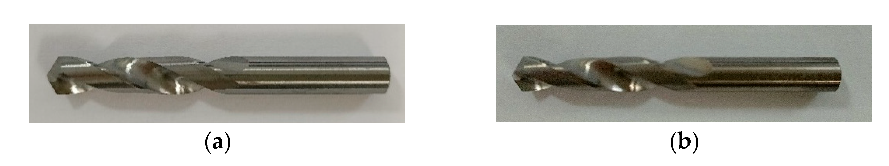
- Drill
2.2. Experiment Method
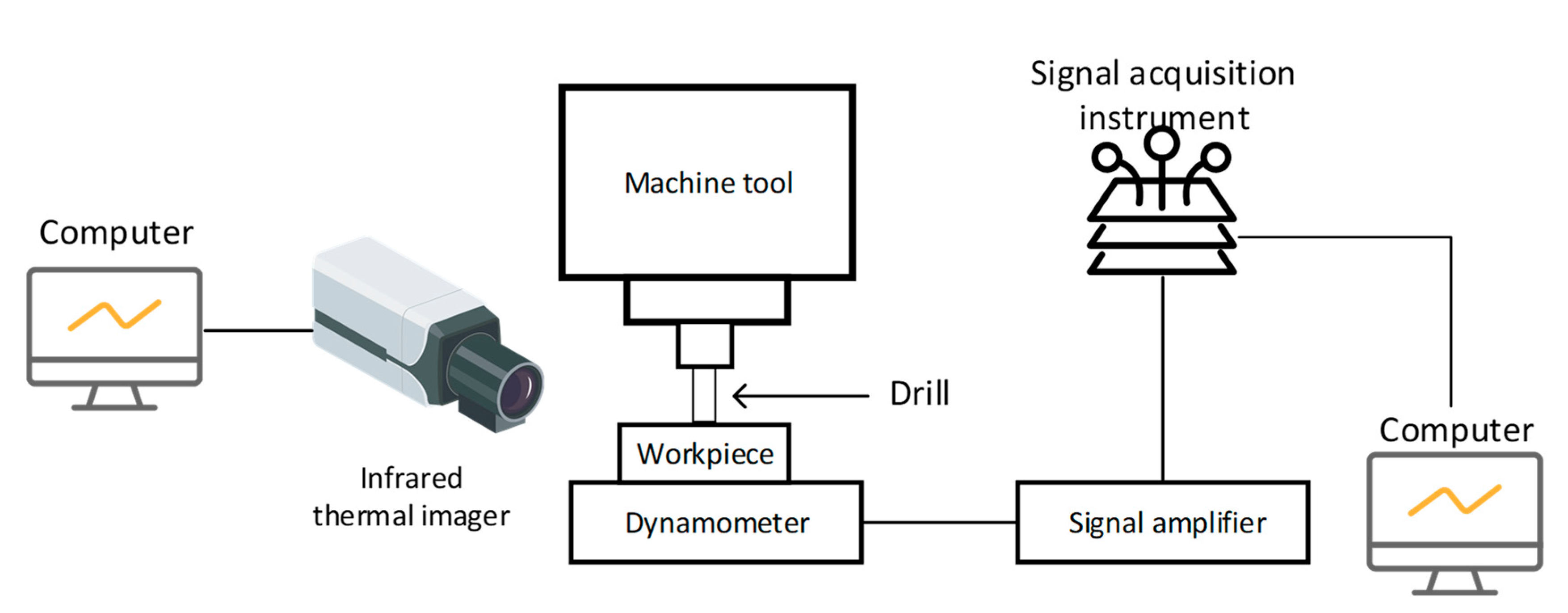
2.3. Experiment Equipment
3. Experiment Results and Analysis
3.1. Dry Drilling Experiment of Uncoated Carbide Bit
3.2. Dry Drilling Experiment of CrAlYN Coated Carbide Bit
- (1)
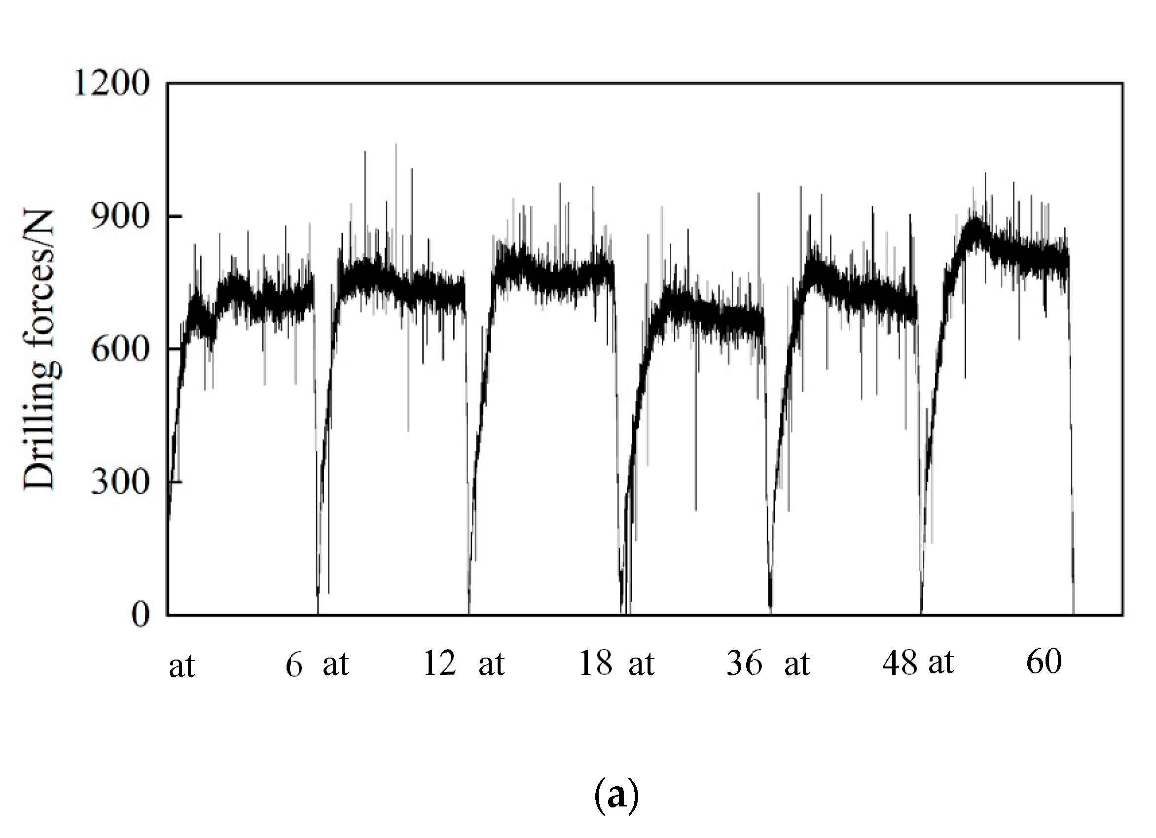
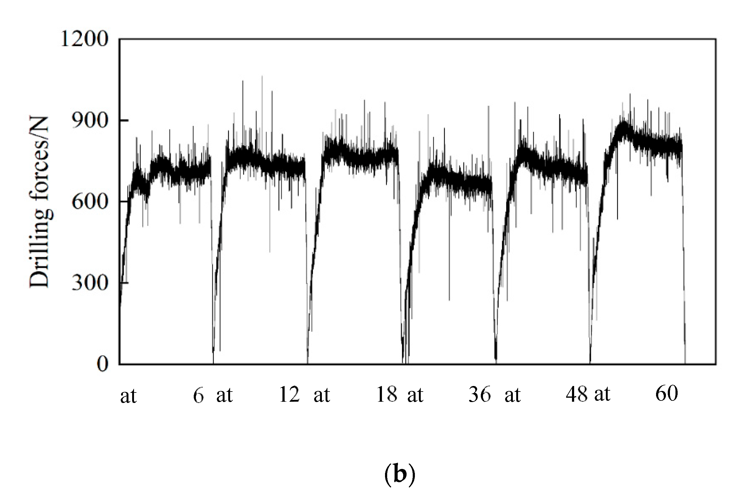
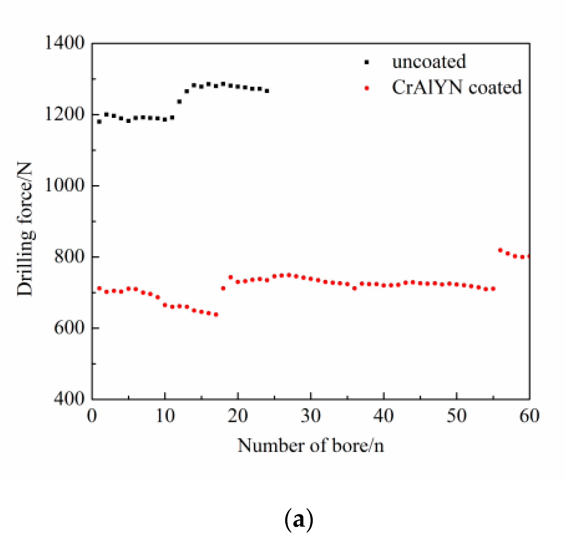
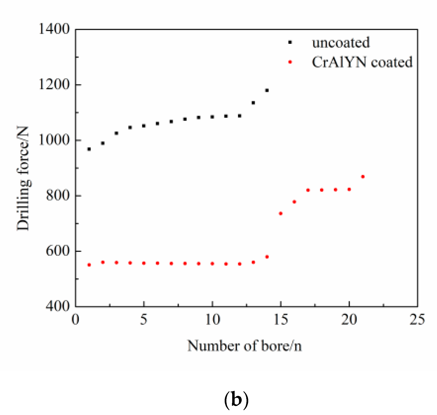
- Comparison of drilling force
- (2)
- Drilling temperature comparison
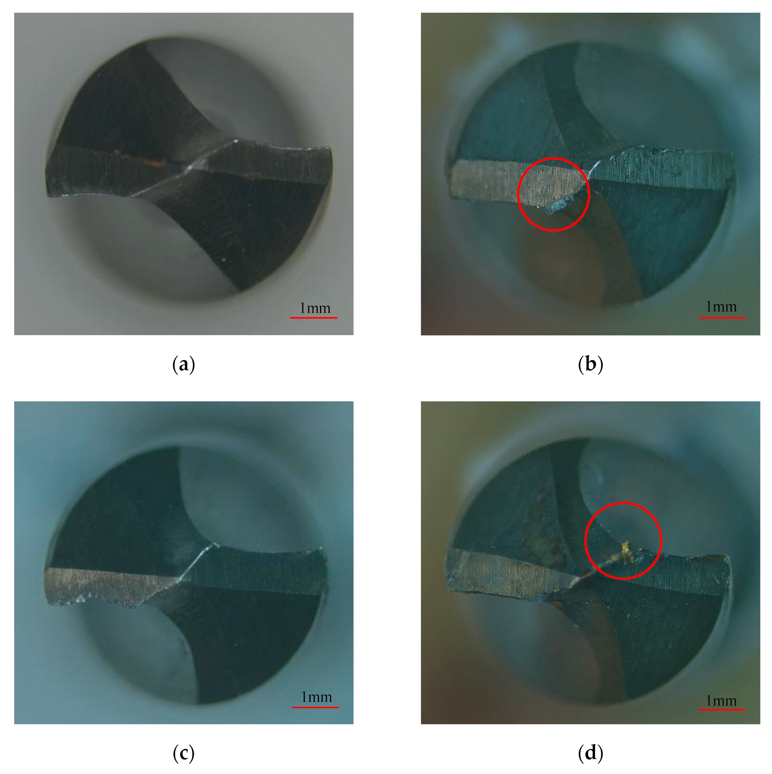
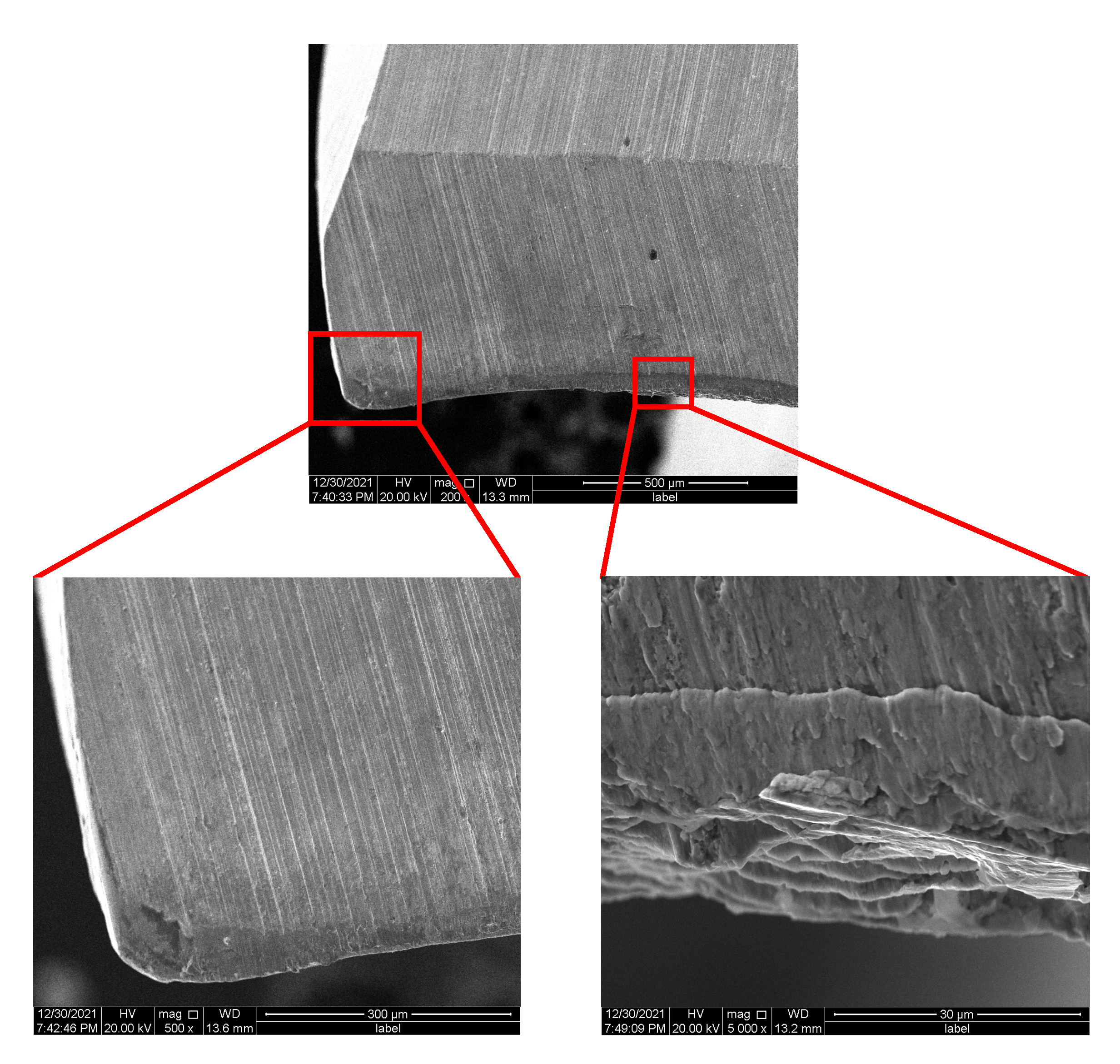
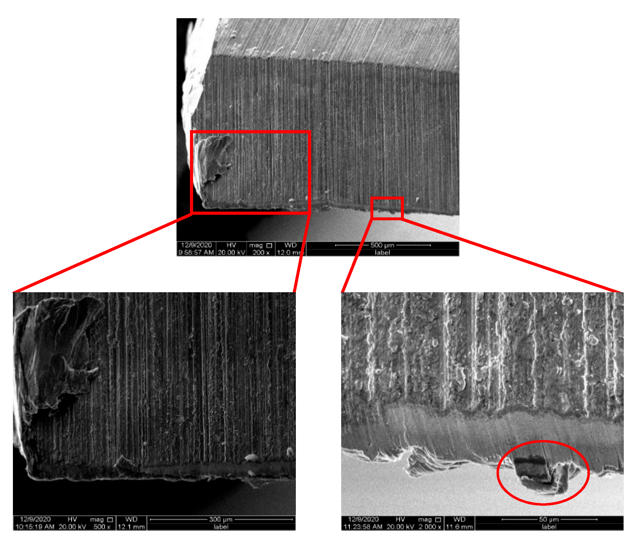
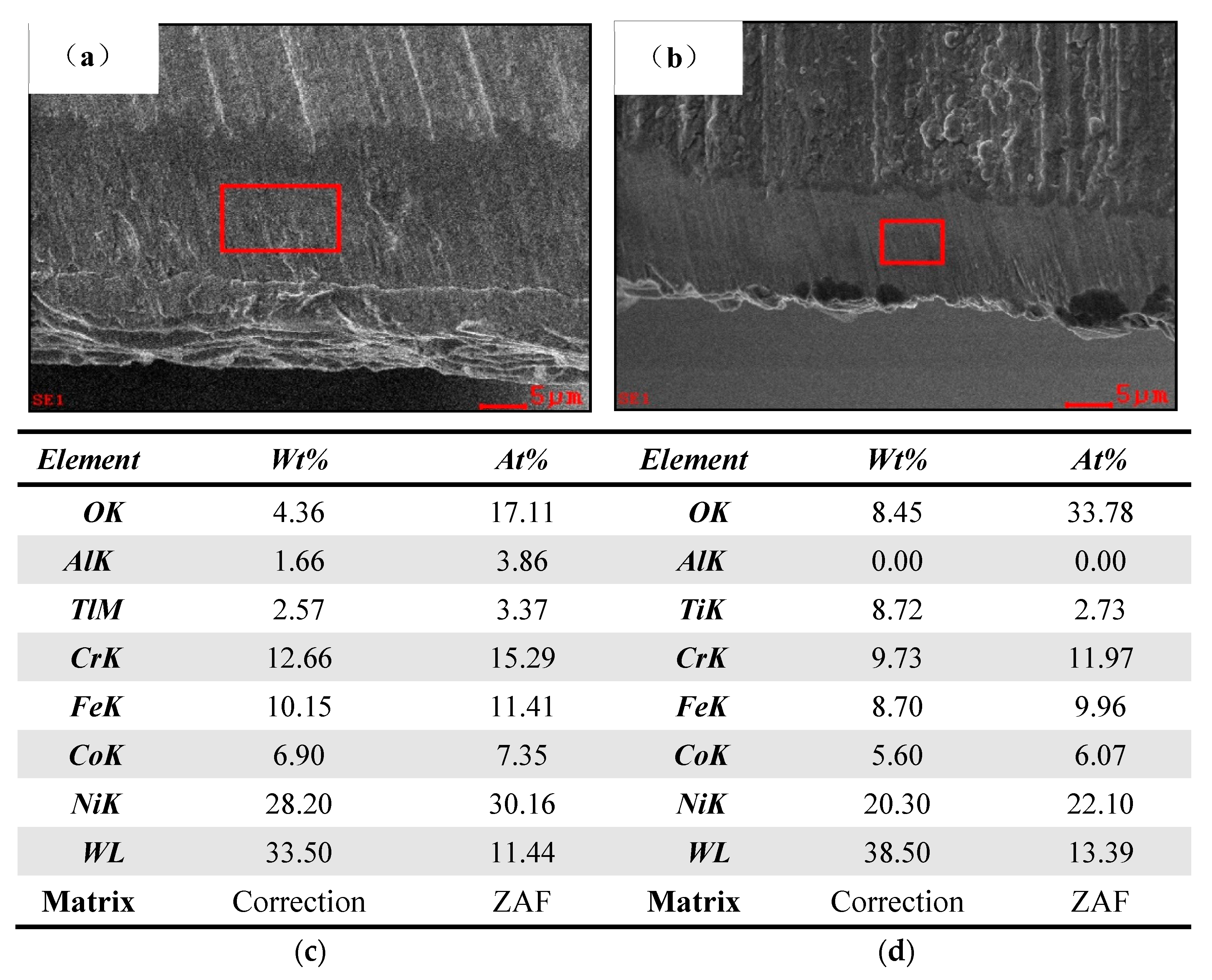
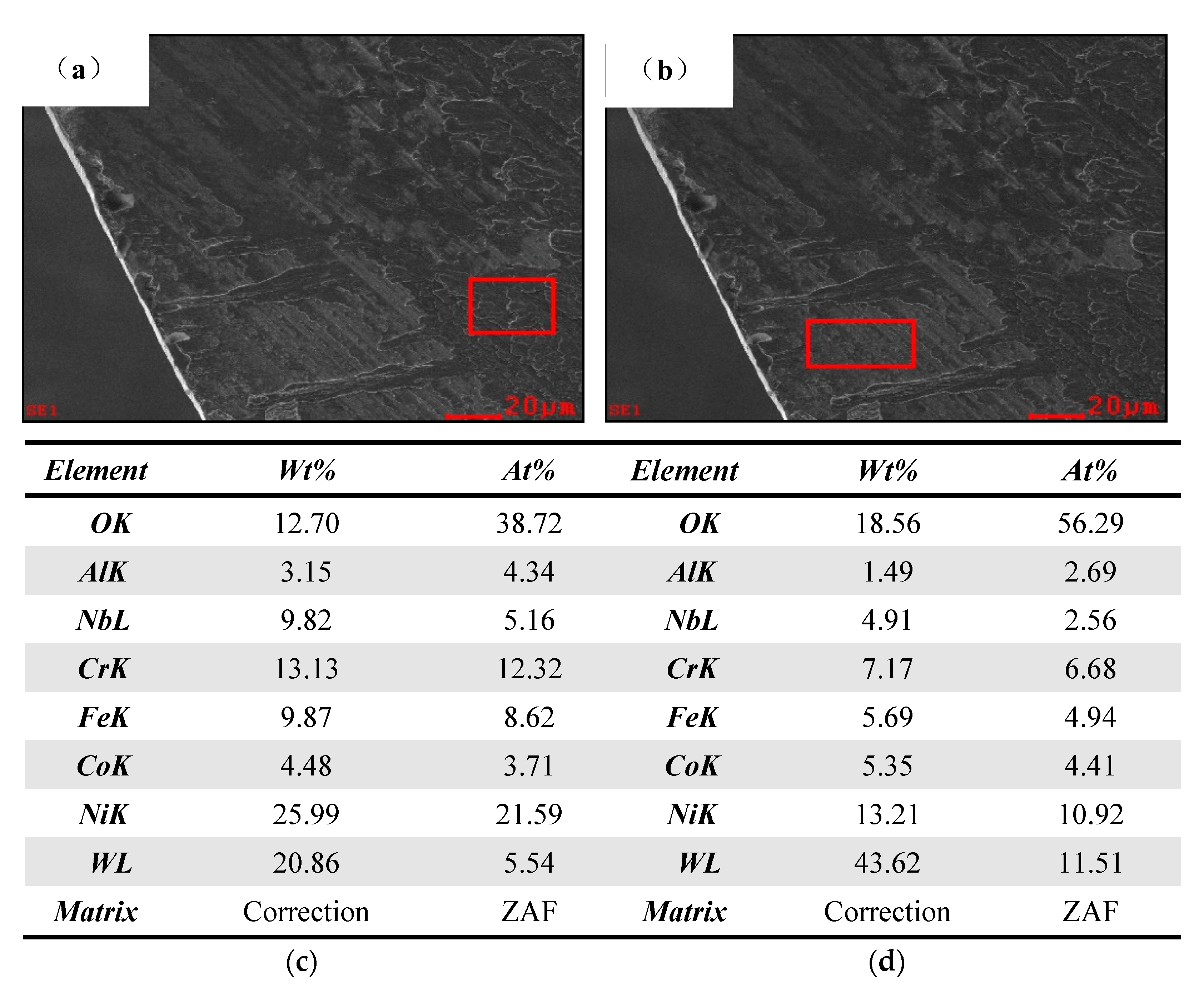
3.3. Bit Wear Morphology
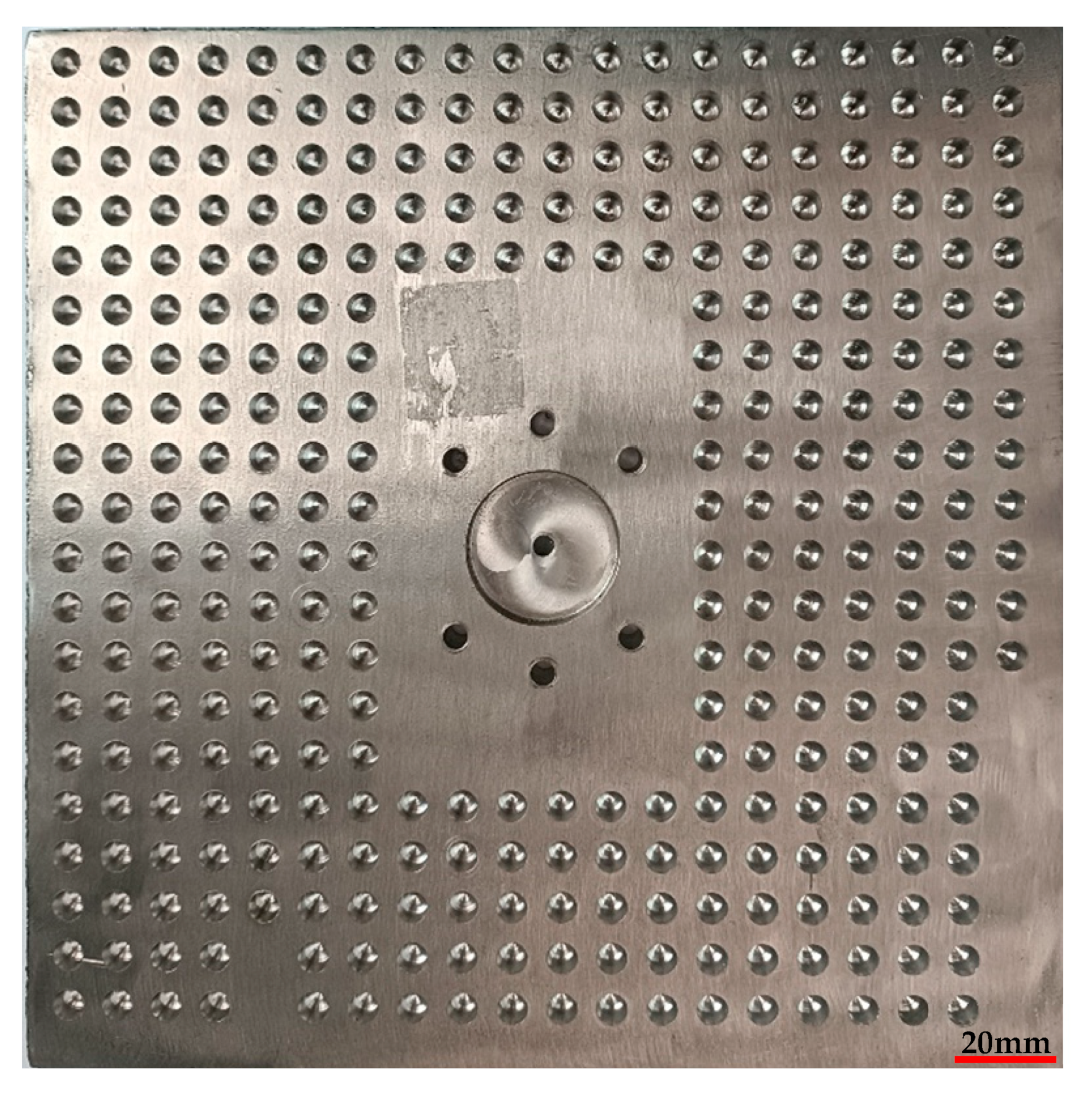
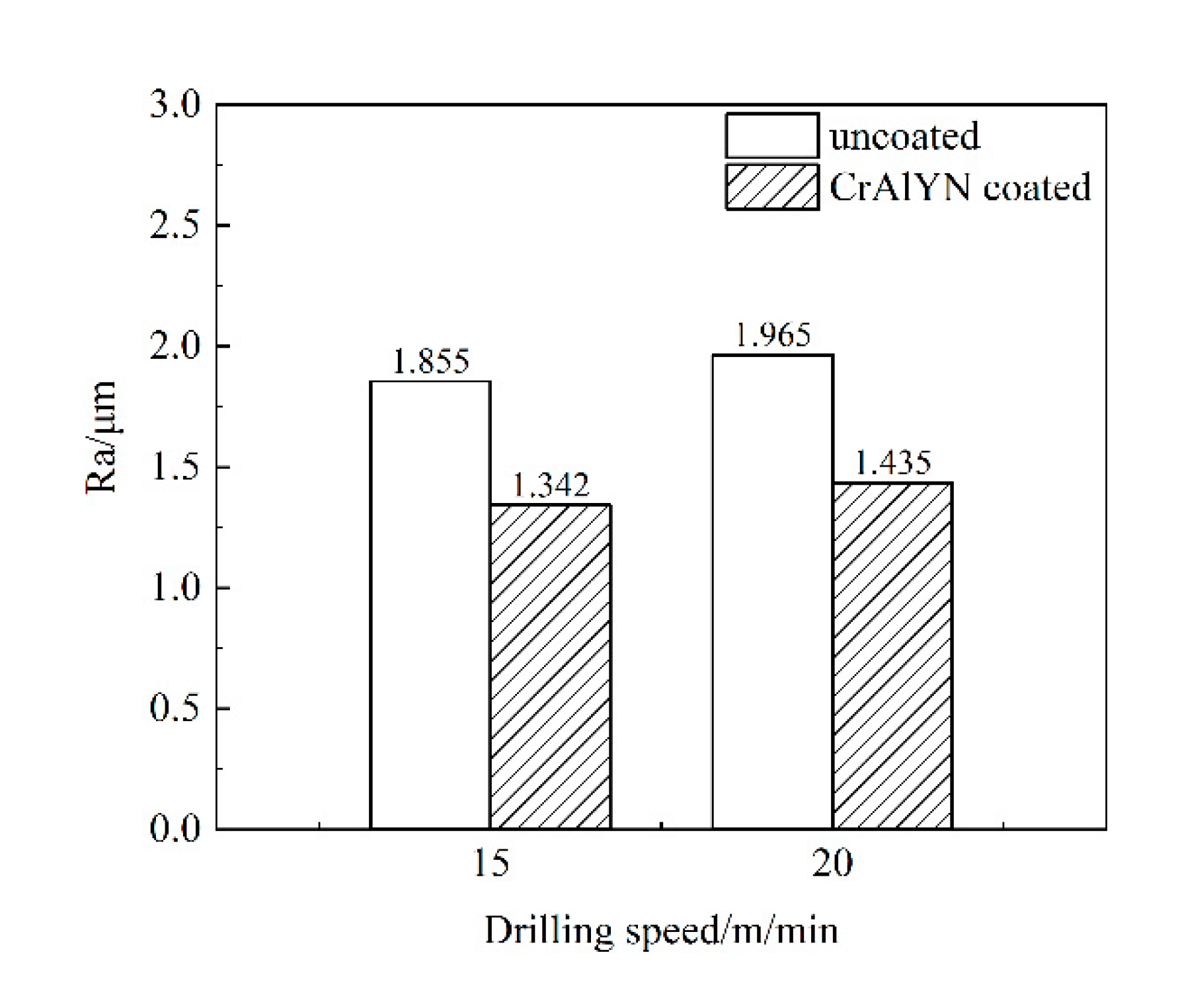
3.4. The Machined Surface Quality
4. Conclusions
- (1)
- In the dry drilling condition, the primary factor influencing the dry drilling of nickel-based superalloy of carbide bit is the drilling depth, which is mainly reflected by the drilling temperature. At the drilling speed of 15 m/min, the bit has a longer service life, lower drilling temperature, smaller drilling force, and more stable drilling state;
- (2)
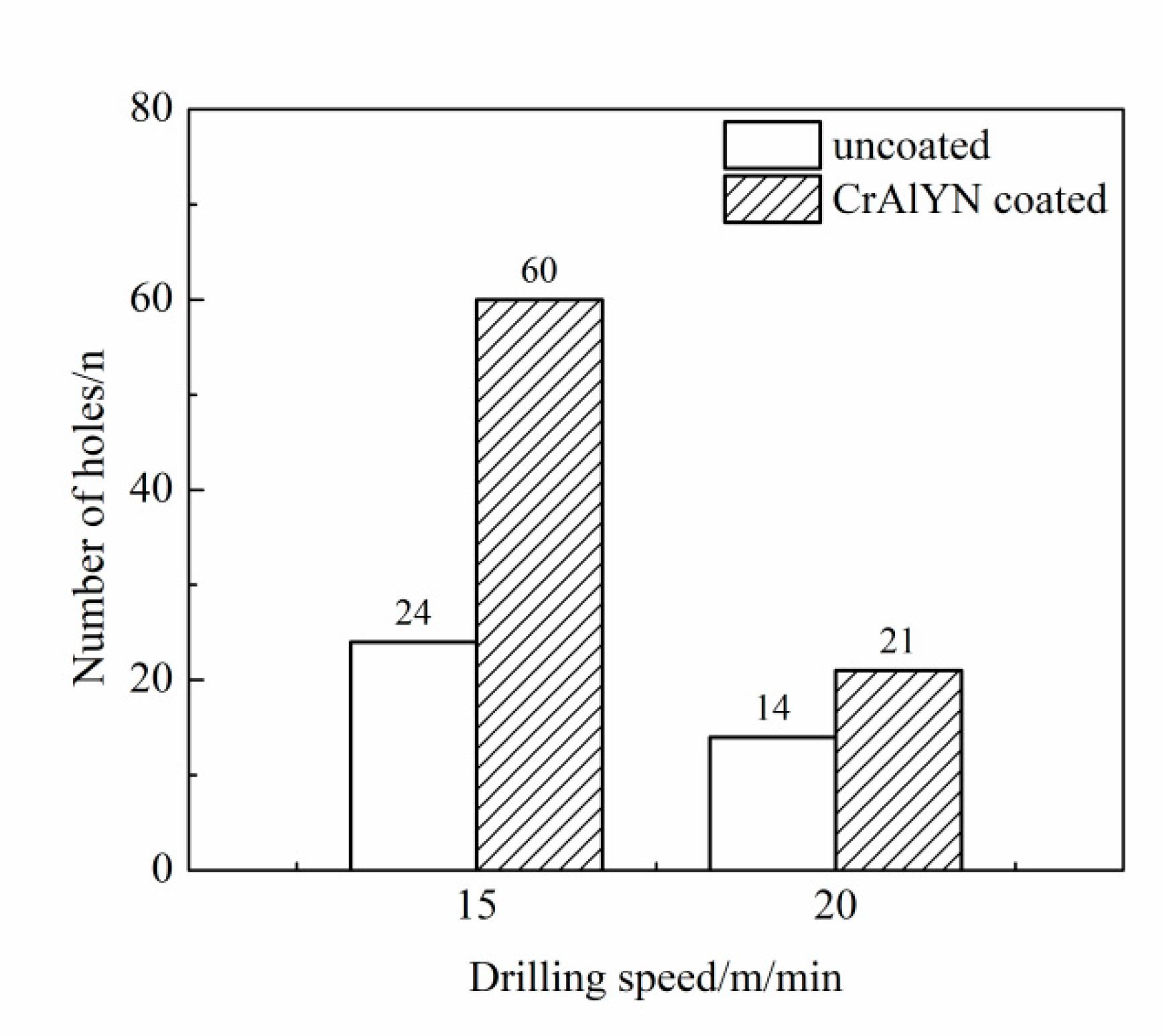
- At lower rotation speeds, the CrAlYN coating can protect the carbide bit matrix and significantly prolongs the bit service life. To be specific, it can prolong the bit service life by 250% at a drilling speed of 15 m/min and 50% at a drilling speed of 20 m/min;
- (3)
- CrAlYN coating can reduce drilling forces and drilling temperature, retard the formation and propagation of surface cracks, delay tool wear, and improve the quality of a machined surface;
- (4)
- The failure mode of coated cemented carbide bit is similar to that of the uncoated cemented carbide bit after the CrAlYN coating falls off in the wear zone of the carbide bit, which is mainly bonding wear on the rear tool surface and the front tool surface.
Author Contributions
Funding
Informed Consent Statement
Data Availability Statement
Acknowledgments
Conflicts of Interest
References
- Moreau, E.; Corbin, S. Assessing the influence of Cr and Fe in the filler metal on dissolution and isothermal solidification kinetics during TLPB of Ni-based superalloys. Metall. Mater. Trans. A 2020, 51, 6307–6317. [Google Scholar] [CrossRef]
- Cheng, Y.; Wang, G.; Liu, J.; He, L. Atomic configurations of planar defects in μ phase in Ni-based superalloys. Scr. Mater. 2021, 193, 27–32. [Google Scholar] [CrossRef]
- Gupta, S.; Bronkhorst, C.A. Crystal plasticity model for single crystal Ni-based superalloys: Capturing orientation and temperature dependence of flow stress. Int. J. Plast. 2021, 137, 102896. [Google Scholar] [CrossRef]
- Ezugwu, E.; Bonney, J.; Yamane, Y. An overview of the machinability of aeroengine alloys. J. Mater. Process. Technol. 2003, 134, 233–253. [Google Scholar] [CrossRef]
- Wang, Z.; Liu, B.; Zhao, Z.; Bai, P.; Dong, M.; Zhang, J.; Fan, J.; Ding, T.; Guo, Z. Formability and hardness studies of selective laser melting of GH4169 Ni-based alloy powders. Emerg. Mater. Res. 2020, 9, 758–769. [Google Scholar] [CrossRef]
- Thakur, D.; Ramamoorthy, B.; Vijayaraghavan, L. Effect of posttreatments on the performance of tungsten carbide (K20) tool while machining (turning) of Inconel 718. Int. J. Adv. Manuf. Technol. 2015, 76, 587–596. [Google Scholar] [CrossRef]
- Okafor, A.C.; Jasra, P.M. Effects of cooling strategies and tool coatings on cutting forces and tooth frequency in high-speed down-milling of Inconel-718 using helical bull-nose solid carbide end mills. Int. J. Adv. Manuf. Technol. 2018, 97, 2301–2318. [Google Scholar] [CrossRef]
- Lu, X.; Jia, Z.; Wang, H.; Si, L.; Liu, Y.; Wu, W. Tool wear appearance and failure mechanism of coated carbide tools in micro-milling of Inconel 718 super alloy. Ind. Lubr. Tribol. 2016, 68, 267–277. [Google Scholar] [CrossRef]
- Kursuncu, B.; Caliskan, H.; Guven, S.Y.; Panjan, P. Improvement of cutting performance of carbide cutting tools in milling of the Inconel 718 superalloy using multilayer nanocomposite hard coating and cryogenic heat treatment. Int. J. Adv. Manuf. Technol. 2018, 97, 467–479. [Google Scholar] [CrossRef]
- Wang, B.; Liu, Z. Influences of tool structure, tool material and tool wear on machined surface integrity during turning and milling of titanium and nickel alloys: A review. Int. J. Adv. Manuf. Technol. 2018, 98, 1925–1975. [Google Scholar] [CrossRef]
- Okafor, A.C.; Jasra, P.M. Effects of milling methods and cooling strategies on tool wear, chip morphology and surface roughness in high speed end-milling of Inconel-718. Int. J. Mach. Mach. Mater. 2019, 21, 3–42. [Google Scholar] [CrossRef]
- Zhao, B.; Khader, I.; Liu, H.; Zhou, T.; Konrath, G.; Kailer, A. Tribological characterization of an alumina-based composite in dry sliding contact against laser-heated and unheated Inconel 718. Tribol. Int. 2021, 155, 106773. [Google Scholar] [CrossRef]
- Zhuang, K.; Zhu, D.; Zhang, X.; Ding, H. Notch wear prediction model in turning of Inconel 718 with ceramic tools considering the influence of work hardened layer. Wear 2014, 313, 63–74. [Google Scholar] [CrossRef]
- Kiswanto, G.; Azmi, M.; Mandala, A.; Zariatin, D.L.; Ko, T.J. Machining Parameters Mapping’s of Inconel 718 and Aluminum Alloy 1100 in Micro-Milling Process. In Proceedings of the Key Engineering Materials, Madrid, Spain, 26–29 March 2020; pp. 99–104. [Google Scholar]
- Hafiz, M.; Kasim, M.; Mohamad, W.; Izamshah, R.; Aziz, M.; Akmal, M.; Othman, I.; Sundi, S. Machinability ultrasonic assisted milling of Inconel 718 by using Taguchi method. ARPN J. Eng. Appl. Sci. 2006, 13. [Google Scholar]
- Senthilkumaar, J.; Selvarani, P.; Arunachalam, R. Intelligent optimization and selection of machining parameters in finish turning and facing of Inconel 718. Int. J. Adv. Manuf. Technol. 2012, 58, 885–894. [Google Scholar] [CrossRef]
- Zhou, J.; Bushlya, V.; Avdovic, P.; Ståhl, J.E. Study of surface quality in high speed turning of Inconel 718 with uncoated and coated CBN tools. Int. J. Adv. Manuf. Technol. 2012, 58, 141–151. [Google Scholar] [CrossRef]
- Ahmed, A.; Tanjilul, M.; Rahman, M.; Kumar, A.S. Ultrafast drilling of Inconel 718 using hybrid EDM with different electrode materials. Int. J. Adv. Manuf. Technol. 2020, 106, 2281–2294. [Google Scholar] [CrossRef]
- Gao, C.; Liu, Z.; Xie, T.; Guo, C. Influence of electrical discharge machining on thermal barrier coating in a two-step drilling of nickel-based superalloy. Arab. J. Sci. Eng. 2021, 46, 2009–2020. [Google Scholar] [CrossRef]
- Bassoli, E.; Denti, L.; Gatto, A.; Iuliano, L. Influence of electrode size and geometry in electro-discharge drilling of Inconel 718. Int. J. Adv. Manuf. Technol. 2016, 86, 2329–2337. [Google Scholar] [CrossRef]
- Wang, R.; Wang, K.; Dong, X.; Fan, Z.; Duan, W.; Mei, X.; Wang, W.; Cui, J.; Zhang, S. An experimental investigation into the defects of laser-drilled holes in thermal barrier coated Inconel 718 superalloys. Int. J. Adv. Manuf. Technol. 2018, 96, 1467–1481. [Google Scholar] [CrossRef]
- Chien, W.-T.; Hou, S.-C. Investigating the recast layer formed during the laser trepan drilling of Inconel 718 using the Taguchi method. Int. J. Adv. Manuf. Technol. 2007, 33, 308–316. [Google Scholar] [CrossRef]
- Shin, J.; Mazumder, J. Shallow angle drilling of inconel 718 using a helical laser drilling technique. J. Manuf. Sci. Eng. 2017, 139, 031004. [Google Scholar] [CrossRef]
- Sharman, A.; Amarasinghe, A.; Ridgway, K. Tool life and surface integrity aspects when drilling and hole making in Inconel 718. J. Mater. Process. Technol. 2008, 200, 424–432. [Google Scholar] [CrossRef]
- Eckstein, M.; Vrabeľ, M.; Maňková, I. Tool Wear and Surface Roughness Evolution in Hole Making Process of Inconel 718. In Materials Science Forum; Trans Tech Publications Ltd.: Freienbach, Switzerland, 2016; Volume 862, pp. 11–17. [Google Scholar]
- Kannan, S.; Pervaiz, S.; Vincent, S.; Karthikeyan, R. Tool Life and Surface Integrity Aspects when Drilling Nickel Alloy. In Proceedings of the IOP Conference Series: Materials Science and Engineering, Bangkok, Thailand, 24–26 February 2018; p. 012042. [Google Scholar]
- Jinliang, S. Chip Formation Mechanism and Tool Wear in Drilling Superalloy; Shenyang Ligong University: Shen Yang, China, 2017. [Google Scholar]
- Dudzinski, D.; Devillez, A.; Moufki, A.; Larrouquere, D.; Zerrouki, V.; Vigneau, J. A review of developments towards dry and high speed machining of Inconel 718 alloy. Int. J. Mach. Tools Manuf. 2004, 44, 439–456. [Google Scholar] [CrossRef]
- Cantero, J.L.; Díaz-Álvarez, J.; Infante-García, D.; Rodríguez, M.; Criado, V. High speed finish turning of inconel 718 using pcbn tools under dry conditions. Metals 2018, 8, 192. [Google Scholar] [CrossRef] [Green Version]
- Ramanujam, R.; Venkatesan, K.; Saxena, V.; Joseph, P. Modeling and optimization of cutting parameters in dry turning of Inconel 718 using coated carbide inserts. Proced. Mater. Sci. 2014, 5, 2550–2559. [Google Scholar] [CrossRef] [Green Version]
- Umbrello, D. Investigation of surface integrity in dry machining of Inconel 718. Int. J. Adv. Manuf. Technol. 2013, 69, 2183–2190. [Google Scholar] [CrossRef]
- Le Coz, G.; Dudzinski, D. Temperature variation in the workpiece and in the cutting tool when dry milling Inconel 718. Int. J. Adv. Manuf. Technol. 2014, 74, 1133–1139. [Google Scholar] [CrossRef]
- Yan, S.; Zhu, D.; Zhuang, K.; Zhang, X.; Ding, H. Modeling and analysis of coated tool temperature variation in dry milling of Inconel 718 turbine blade considering flank wear effect. J. Mater. Process. Technol. 2014, 214, 2985–3001. [Google Scholar] [CrossRef]
- Lijing, B.; Shan, Z.; Yongzhong, J.; Peng, Y.; Zhihu, W. The influence of Y content on the thermal oxidation behavior of Cr_xAl_yY_(1-X-Y)N coating. Rare Met. Mater. Eng. 2015, 44, 881–886. [Google Scholar]
- Peng, Y. The Influence of Element Y on the Microstructure and Tribological Properties of CrXalyy1-X-yN Coatings Xi’an; Xi’an University of Technology: Xi’an, China, 2017. [Google Scholar]


| Element | Ni | Cr | Nb | Mo | Ti | C | Si | Mn | B | Fe |
|---|---|---|---|---|---|---|---|---|---|---|
| Mass/% | 51.75 | 17 | 5.15 | 2.93 | 1.07 | 0.042 | 0.21 | 0.03 | 0.006 | Maargin |
| Elastic Modulus (GPa) | Poisson’s Ratio μ | Density ρ(Kg/m3) | Johnson–Cook Model Parameters | ||||||
|---|---|---|---|---|---|---|---|---|---|
| A(MPa) | B(MPa) | C | n | m | Tmelt(℃) | Troom(℃) | |||
| 220 | 0.3 | 8420 | 985 | 949 | 0.01 | 0.4 | 1.65 | 1320 | 20 |
| Cutting Tool Serial No. | Element Mass Fraction (%) | ||
|---|---|---|---|
| W | Co | C | |
| YG10 | 84 | 10 | 6 |
| Cutting Tool Serial No. | Mechanical Properties | |||||
|---|---|---|---|---|---|---|
| Density g/cm−3 | Hardness HRA | Bending Strength MPa | Compressive Strength MPa | Elastic Modulus GPa | Impact Toughness J/cm−2 | |
| YG10 | 14.7 | 88.5 | 2700 | 4700 | 585 | 2.8 |
| Coating | Element Content (%) | |||
|---|---|---|---|---|
| Cr | Al | Y | N | |
| CrAlYN | 44.71 | 9.72 | 3.28 | 42.29 |
| Level | Factor | ||
|---|---|---|---|
| Drilling Speed (m/min) | Drilling Feed Rate (r/mm) | Drilling Depth (mm) | |
| 1 | 15 | 0.03 | 3 |
| 2 | 20 | 0.04 | 6 |
| 3 | 25 | 0.05 | 9 |
| Serial No. | Drilling Speed | Feed Rate (mm/r) | Drilling Depth (mm) | Number of Drilling | Drilling Force (N) | Drilling Tem. |
|---|---|---|---|---|---|---|
| (m/min) | (n) | (°C) | ||||
| 1 | 15 | 0.03 | 3 | 36 | 486 | 260 |
| 2 | 15 | 0.04 | 6 | 24 | 1192 | 291 |
| 3 | 15 | 0.05 | 9 | 12 | 863 | 291 |
| 4 | 20 | 0.03 | 6 | 18 | 578 | 248 |
| 5 | 20 | 0.04 | 9 | 6 | 1426 | 369 |
| 6 | 20 | 0.05 | 3 | 16 | 1022 | 302 |
| 7 | 25 | 0.03 | 9 | 4 | 1736 | 363 |
| 8 | 25 | 0.04 | 3 | 60 | 885 | 311 |
| 9 | 25 | 0.05 | 6 | 6 | 1821 | 378 |
| Level | Drilling Speed | Feed Rate | Drilling Depth | ||||||
|---|---|---|---|---|---|---|---|---|---|
| 15 m/min | 20 m/min | 25 m/min | 0.03 mm/r | 0.04 mm/r | 0.05 mm/r | 3 mm | 6 mm | 9 mm | |
| Ki | 72 | 40 | 70 | 58 | 90 | 34 | 112 | 48 | 22 |
| ki | 24 | 13 | 23 | 19 | 30 | 11 | 37 | 16 | 7 |
| Range | 11 | 19 | 30 | ||||||
| Order: Drilling depth > Feed rate > Drilling speed | |||||||||
| Optimization scheme: drilling speed: 15 m/min; feed rate: 0.04 mm/r; drilling depth: 3 mm | |||||||||
| Level | Drilling Speed | Feed Rate | Drilling Depth | ||||||
|---|---|---|---|---|---|---|---|---|---|
| 15 m/min | 20 m/min | 25 m/min | 0.03 mm/r | 0.04 mm/r | 0.05 mm/r | 3 mm | 6 mm | 9 mm | |
| Ki | 2541 | 3026 | 4442 | 2800 | 3503 | 3706 | 2393 | 3591 | 4025 |
| ki | 847 | 1008.67 | 1480.67 | 933.33 | 1167.67 | 1235.33 | 797.67 | 1197 | 1341.67 |
| Range | 633.67 | 302 | 544 | ||||||
| Order: Drilling speed > Drilling depth > Feed rate | |||||||||
| Optimization scheme: drilling speed: 15 m/min; feed rate: 0.03 mm/r; drilling depth: 3 mm | |||||||||
| Level | Drilling Speed | Feed Rate | Drilling Depth | ||||||
|---|---|---|---|---|---|---|---|---|---|
| 15 m/min | 20 m/min | 25 m/min | 0.03 mm/r | 0.04 mm/r | 0.05 mm/r | 3 mm | 6 mm | 9 mm | |
| Ki | 842 | 919 | 1052 | 871 | 971 | 971 | 873 | 917 | 1023 |
| ki | 280.67 | 306.33 | 350.67 | 290.33 | 323.67 | 323.67 | 291 | 305.67 | 341 |
| Range | 70 | 33.34 | 50 | ||||||
| Order: Drilling depth > Feed rate> Drilling speed | |||||||||
| Optimization scheme: drilling speed: 15 m/min; feed rate: 0.04 mm/r; drilling depth: 3 mm | |||||||||
Publisher’s Note: MDPI stays neutral with regard to jurisdictional claims in published maps and institutional affiliations. |
© 2022 by the authors. Licensee MDPI, Basel, Switzerland. This article is an open access article distributed under the terms and conditions of the Creative Commons Attribution (CC BY) license (https://creativecommons.org/licenses/by/4.0/).
Share and Cite
Li, H.; Gao, F.; Li, Y.; Bai, L. Experimental Study on the Dry Drilling Nickel-Based Superalloy of CrAlYN Coated Carbide Bit. Materials 2022, 15, 4302. https://doi.org/10.3390/ma15124302
Li H, Gao F, Li Y, Bai L. Experimental Study on the Dry Drilling Nickel-Based Superalloy of CrAlYN Coated Carbide Bit. Materials. 2022; 15(12):4302. https://doi.org/10.3390/ma15124302
Chicago/Turabian StyleLi, Hui, Feng Gao, Yan Li, and Lijing Bai. 2022. "Experimental Study on the Dry Drilling Nickel-Based Superalloy of CrAlYN Coated Carbide Bit" Materials 15, no. 12: 4302. https://doi.org/10.3390/ma15124302
APA StyleLi, H., Gao, F., Li, Y., & Bai, L. (2022). Experimental Study on the Dry Drilling Nickel-Based Superalloy of CrAlYN Coated Carbide Bit. Materials, 15(12), 4302. https://doi.org/10.3390/ma15124302