
Wear Mechanisms and Notch Formation of Whisker-Reinforced Alumina and Sialon Ceramic Tools during High-Speed Turning of Inconel 718

Abstract
:1. Introduction
2. Experimental Details
3. Results and Discussion
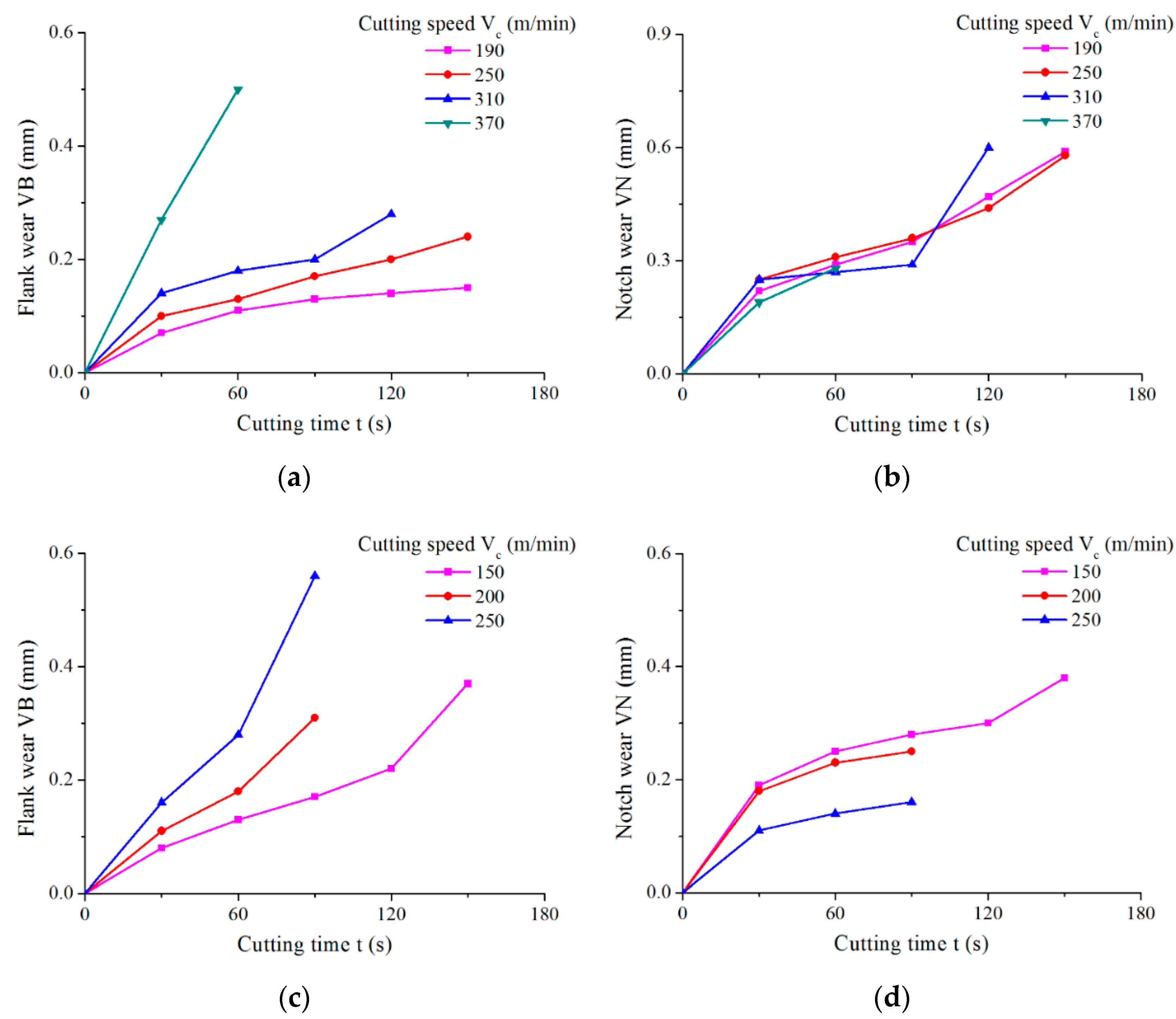
3.1. Preliminary Cutting Test
3.2. Wear Processes
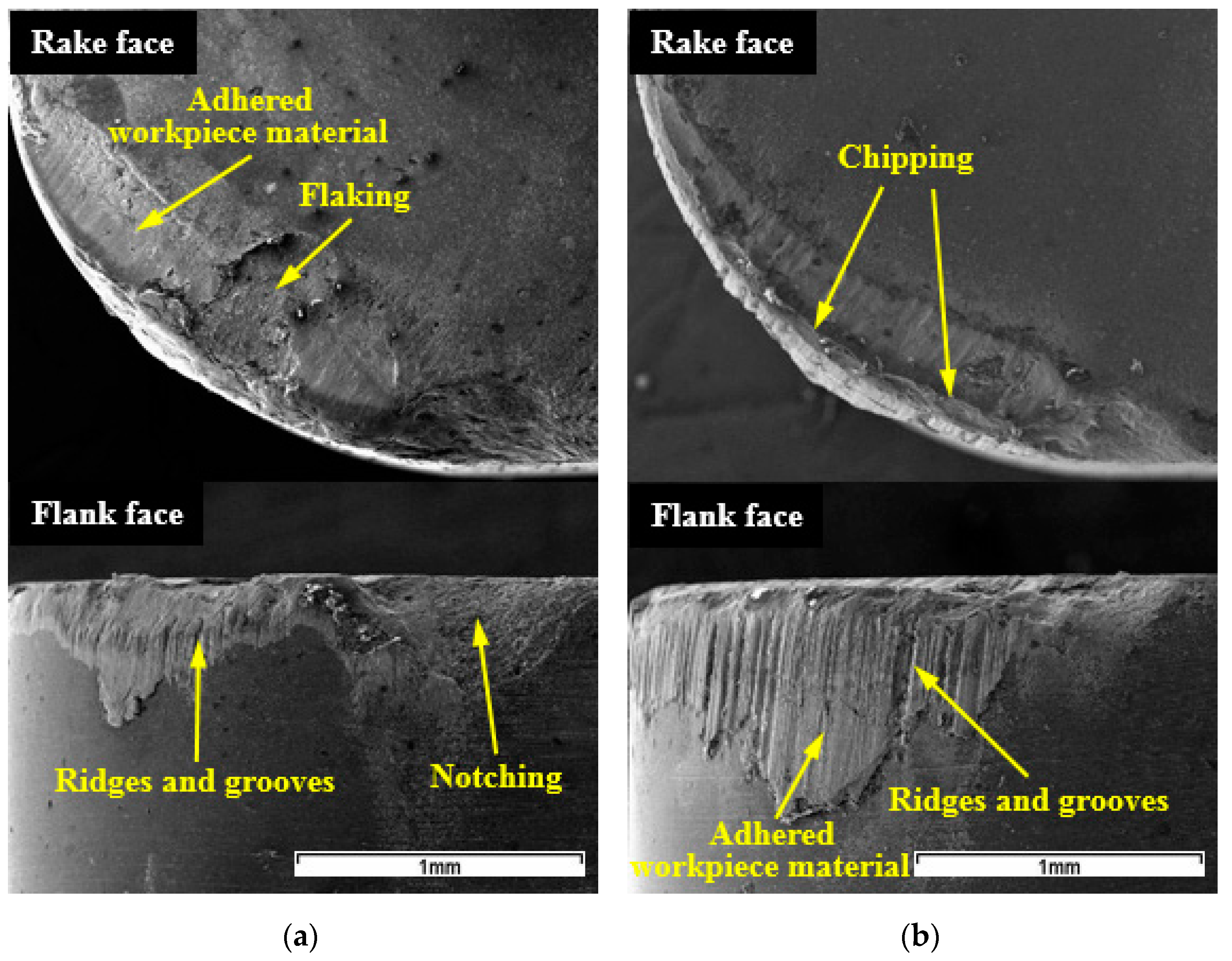
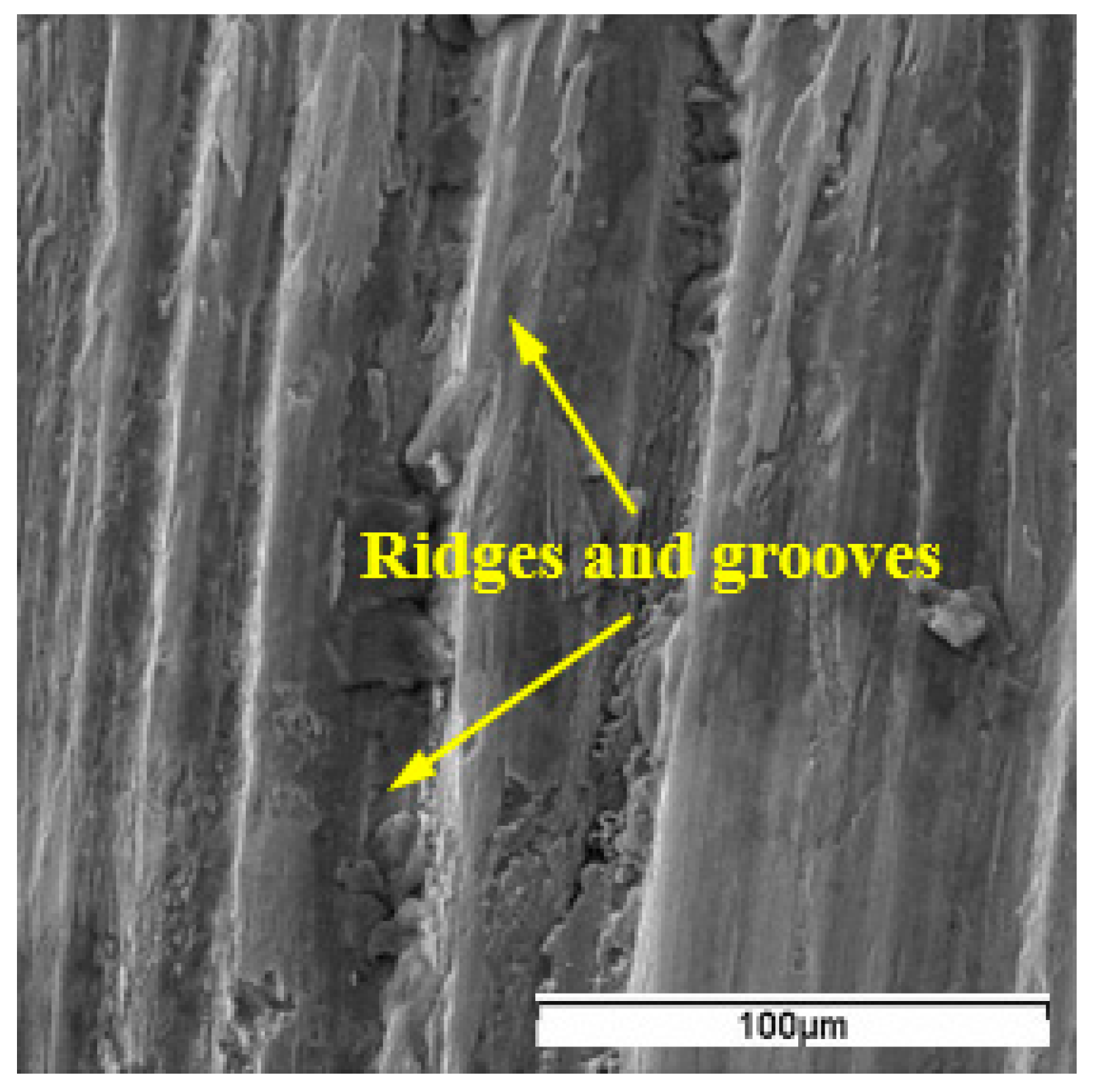
3.3. Wear Patterns
3.4. Wear Mechanisms
3.4.1. Abrasion
3.4.2. Adhesion
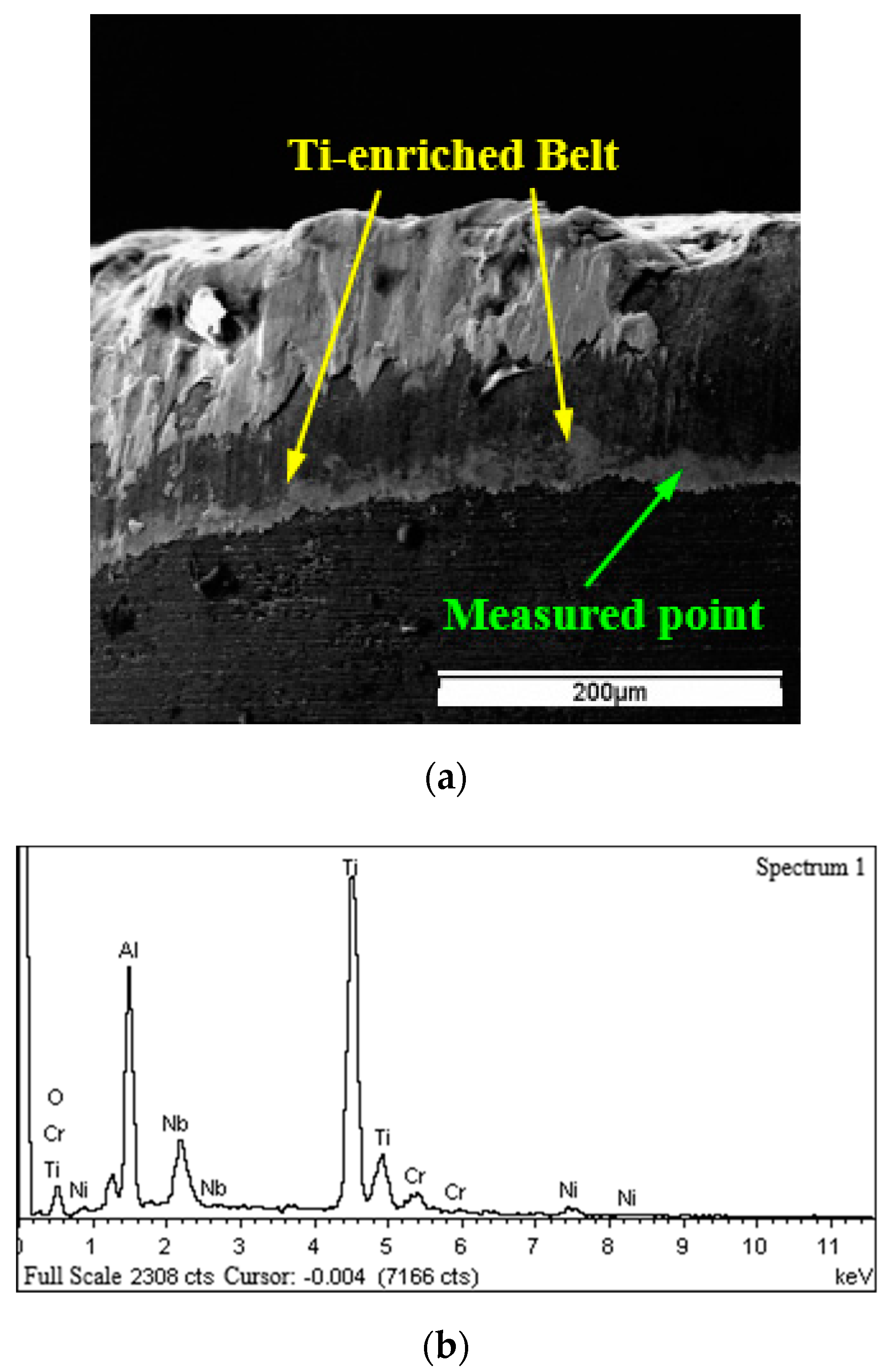
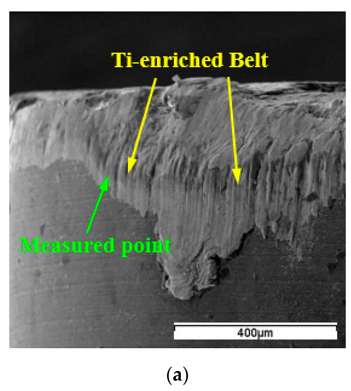
3.4.3. Diffusion and Chemical Reactions
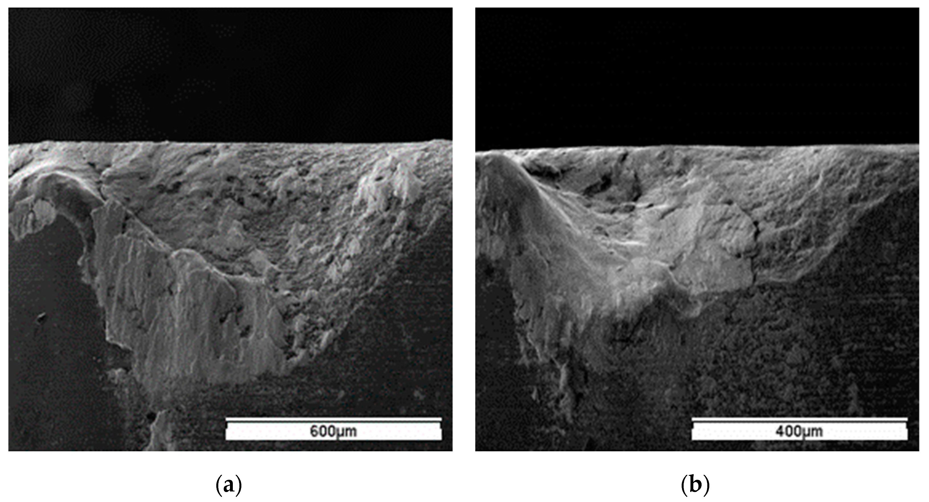
3.5. Notch Formation
3.6. Limitation and Future Work
4. Conclusions
- (1)
- The SiC whisker-reinforced alumina WG300 and Sialon SX9 experienced distinct wear processes. The notch wear dominated the whole wear process of WG300 at low cutting speeds and the transition to flank wear occurred at the cutting speed of 370 m/min. In contrast, the notch wear of SX9 gradually decreased as the cutting speed increased, and the tool attained the wear criteria in the form of flank wear at all cutting speeds.
- (2)
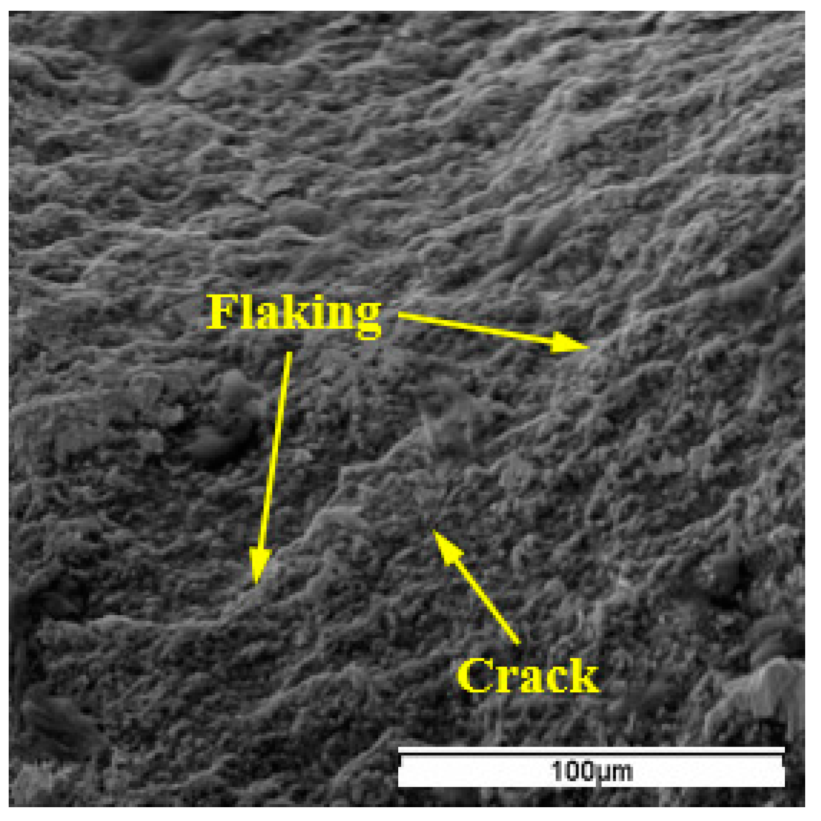
- The notching at the depth-of-cut line was the typical wear mode for WG300, while SX9 was characterized by ridges and grooves perpendicular to the cutting edge. With an increase in cutting speed, chipping of the edge and flaking of the rake face occurred for both ceramic tools. Additionally, notching at the minor cutting edge and the collapse of the tool nose were detected for WG300 at higher cutting speeds.
- (3)
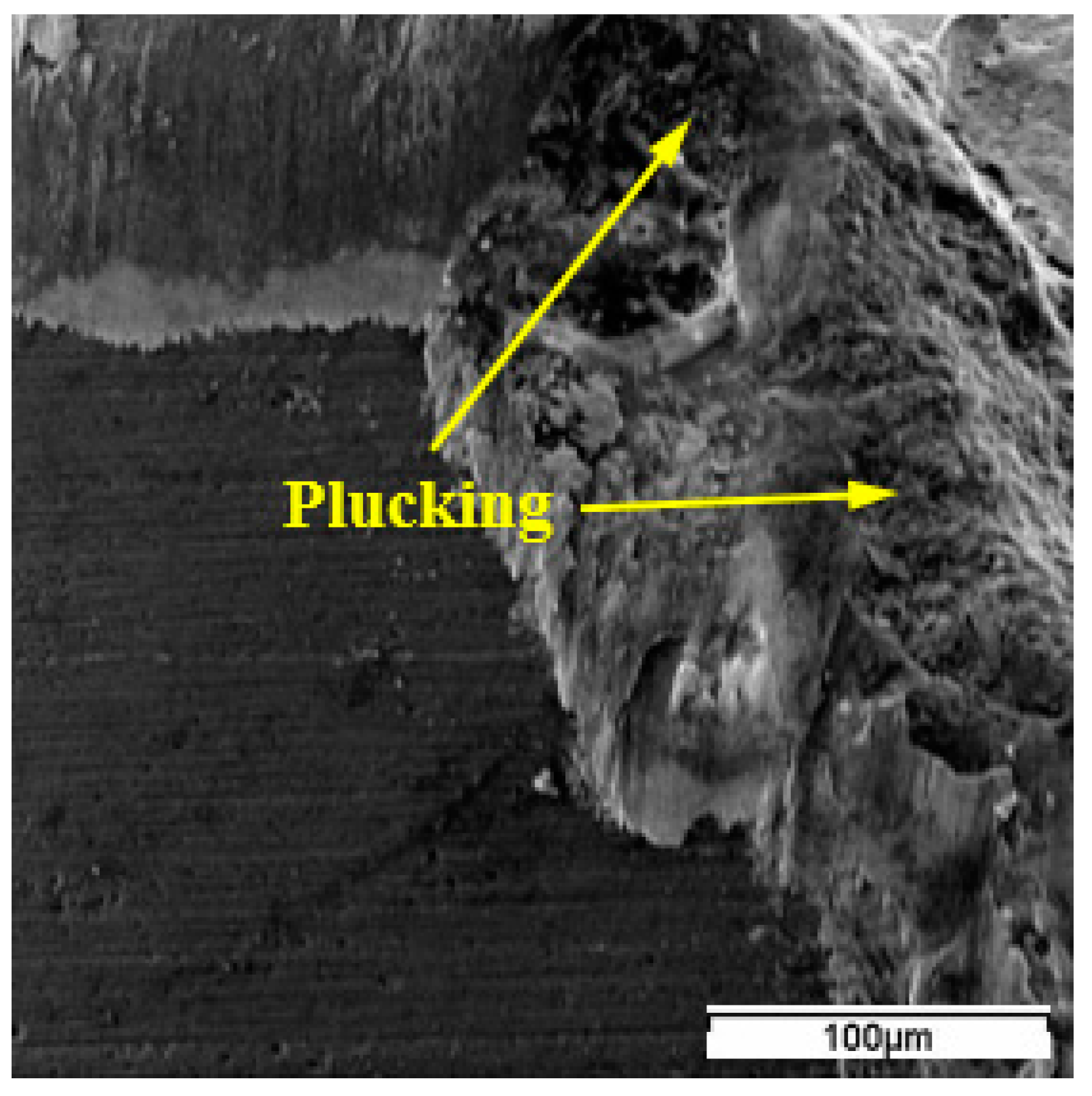
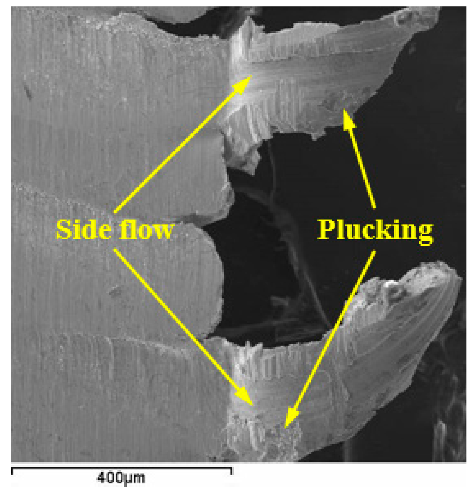
- The hard carbide particles contained in Inconel 718 together with the tool particles dropping from the tool matrix resulted in the abrasive wear of SX9 by high-frequency scraping action. In addition, tool material was plucked off from the tool matrix by periodic attachment and detachment of the adhered workpiece material, leading to the adhesive wear of the ceramic tools.
- (4)
- The Ti−enriched belt generated at the boundary of the wear band and crater indicated the diffusion between the workpiece material and cutting tool elements. The elements Ni, Fe, and Cr diffused along the SiC whiskers or silicon nitride grain boundaries into the tool matrix, while Ti was left on the tool surface due to immediate reaction with an element from the cutting tool. The diffusion undermined the tool matrix by dissolving the SiC whiskers or silicon nitride grains.
- (5)
- The notch formation depended on the thermal shock resistance and fracture toughness of the ceramic tools at its initial stage, while at the expanding stage, the evolution of notching was dominated by the adhesion mechanism. The high contents of element O and Cr at the notching suggested that the oxidation of the workpiece material occurred at this position. The oxidation of the workpiece material could reduce the affinity for the tool, and thus had a positive effect on decreasing the notch wear of ceramic tools.
Author Contributions
Funding
Institutional Review Board Statement
Informed Consent Statement
Data Availability Statement
Conflicts of Interest
References
- Arunachalam, R.; Mannan, M.A. Machinability of nickel-based high temperature alloys. Mach. Sci. Technol. 2000, 4, 127–168. [Google Scholar] [CrossRef]
- Ulutan, D.; Ozel, T. Machining induced surface integrity in titanium and nickel alloys: A. review. Int. J. Mach. Tool. Manuf. 2011, 51, 250–280. [Google Scholar] [CrossRef]
- Ezugwu, E.O.; Zhang, Z.M.; Machado, A.R. The machinability of nickel-based alloys: A review. J. Mater. Process. Technol. 1999, 86, 1–16. [Google Scholar] [CrossRef]
- Cantero, J.L.; Díaz-Álvarez, J.; Miguélez, M.H.; Marín, N.C. Analysis of tool wear patterns in finishing turning of Inconel 718. Wear 2013, 297, 885–894. [Google Scholar] [CrossRef] [Green Version]
- Polvorosa, R.; Suárez, A.; de Lacalle, L.N.L.; Cerrillo, I.; Wretland, A.; Veiga, F. Tool wear on nickel alloys with different coolant pressures: Comparison of Alloy 718 and Waspaloy. J. Manuf. Proc. 2017, 26, 44–56. [Google Scholar] [CrossRef]
- Ezugwu, E.O.; Okeke, C.I. Behavior of coated carbide tools in high speed machining of a nickel base alloy. Tribol. Trans. 2002, 45, 122–126. [Google Scholar] [CrossRef]
- Richards, N.; Aspinwall, D. Use of ceramic tools for machining nickel-based alloys. Int. J. Mach. Tool. Manuf. 1989, 29, 575–588. [Google Scholar] [CrossRef]
- Li, L.; He, N.; Wang, M.; Wang, Z.G. High speed cutting of Inconel 718 with coated carbide and ceramic inserts. J. Mater. Process. Technol. 2002, 129, 127–130. [Google Scholar] [CrossRef]
- Fernández-Lucio, P.; Neto, O.P.; Gómez-Escudero, G.; Fuertes, F.J.A.; Valdivielso, A.F.; Marcaide, L.N.L.D. Roughing milling with ceramic tools in comparison with sintered carbide on nickel-based alloys. Coatings 2021, 11, 734. [Google Scholar] [CrossRef]
- Narutaki, N.; Yamane, Y.; Hayashi, K.; Kitagawa, T. High-speed machining of Inconel 718 with ceramic tools. CIRP Ann. Manuf. Technol. 1993, 42, 103–106. [Google Scholar] [CrossRef]
- Sun, J.; Huang, S.; Ding, H.; Chen, W. Cutting performance and wear mechanism of Sialon ceramic tools in high speed face milling GH4099. Ceram. Int. 2020, 46, 1621–1630. [Google Scholar] [CrossRef]
- Ezugwu, E.O.; Tang, S.H. Surface abuse when machining cast iron (G-17) and nickel-base superalloy (Inconel 718) with ceramic tools. J. Mater. Process. Technol. 1995, 55, 63–69. [Google Scholar] [CrossRef]
- Zhuang, K.J.; Zhu, D.H.; Zhang, X.M.; Ding, H. Notch wear prediction model in turning of Inconel 718 with ceramic tools considering the influence of work hardened layer. Wear 2014, 313, 63–74. [Google Scholar] [CrossRef]
- Lee, M.; Horne, J.G.; Tabor, D. The mechanism of notch formation at the depth of cut line of ceramic tools machining nickel-base superalloys. In Proceedings of the International Conference on Wear of Materials, Dearborn, MI, USA; 1979; pp. 460–469. [Google Scholar]
- Shalaby, M.A.; Veldhuis, S.C. Tool wear and chip formation during dry high speed turning of direct aged Inconel 718 aerospace superalloy using different ceramic tools. Proc. IMechE. Part J J. Eng. Tribol. 2019, 233, 1127–1136. [Google Scholar] [CrossRef]
- Wayne, S.F.; Buljan, S.T. Wear of ceramic cutting tools in Ni-based superalloy machining. Tribol. Trans. 1990, 33, 618–626. [Google Scholar] [CrossRef]
- Zhao, J.; Deng, J.X.; Zhang, J.H.; Ai, X. Failure mechanisms of a whisker-reinforced ceramic tool when machining nickel-based alloys. Wear 1997, 208, 220–225. [Google Scholar] [CrossRef]
- Leshock, C.E.; Kim, J.N.; Shin, Y.C. Plasma enhanced machining of Inconel 718: Modeling of workpiece temperature with plasma heating and experimental results. Int. J. Mach. Tool. Manuf. 2001, 41, 877–897. [Google Scholar] [CrossRef]
- Obikawa, T.; Yamaguchi, M. Suppression of notch wear of a whisker reinforced ceramic tool in air-jet-assisted high-speed machining of Inconel 718. Prec. Eng. 2015, 39, 143–151. [Google Scholar] [CrossRef]
- Xue, C.; Chen, W.Y. Adhering layer formation and its effect on the wear of coated carbide tools during turning of a nickel-based alloy. Wear 2011, 270, 895–902. [Google Scholar] [CrossRef]
- Ezugwu, E.O.; Olajire, K.A.; Wang, Z.M. Wear analysis of coated carbide tools when machining nickel base, Inconel 718 alloy. In Proceedings of the International Conference on Surface Modification Technologies, Paris, France, 11–13 September 2000; pp. 279–286. [Google Scholar]
- Itakura, K.; Kuroda, M.; Omokawa, H.; Itani, H.; Yamamoto, K.; Ariura, Y. Wear mechanism of coated cemented carbide tool in cutting of Inconel 718 super-heat-resisting alloy. Int. J. Jpn. Soc. Prec. Eng. 1999, 33, 326–332. [Google Scholar] [CrossRef]
- Trent, E.M. Metal Cutting, 3rd ed.; Butterworth-Heinemann Ltd.: Oxford, UK, 1991. [Google Scholar]
- Kitagawa, T.; Kubo, A.; Maekawa, K. Temperature and wear of cutting tools in high speed machining of Inconel and Ti-6Al-6V-2Sn. Wear 1997, 202, 142–148. [Google Scholar] [CrossRef]
- Brandt, G.; Gerendas, A.; Mikus, M. Wear mechanisms of ceramic cutting tools when machining ferrous and non-ferrous alloys. J. Eur. Ceram Soc. 1990, 6, 273–290. [Google Scholar] [CrossRef]
- Bushlya, V.; Zhou, J.M.; Avdovic, P.; Stahl, J.E. Wear mechanisms of silicon carbide-whisker-reinforced alumina (Al2O3-SiCw) cutting tools when high-speed machining aged Alloy 718. Int. J. Adv. Manuf. Technol. 2013, 68, 1083–1093. [Google Scholar] [CrossRef] [Green Version]
- North, B. Ceramic cutting tools—A. review. Int. J. High Technol. Ceram. 1987, 3, 113–127. [Google Scholar] [CrossRef]
- Wayne, S.F.; Buljan, S.T. The role of thermal shock on tool life of selected ceramic cutting tool materials. J. Am. Ceram. Soc. 1989, 72, 754–760. [Google Scholar] [CrossRef]
- Zheng, L.; Zhang, M.C.; Dong, J.X. Oxidation behavior and mechanism of powder metallurgy Rene95 nickel based superalloy between 800 and 1000 °C. Appl. Surf. Sci. 2010, 256, 7510–7515. [Google Scholar] [CrossRef]
- Khamsehzadeh, H. Behaviour of Ceramic Cutting Tools When Machining Superalloys. Ph.D. Thesis, University of Warwick, Coventry, UK, 1991. [Google Scholar]


| C | Si | Al | Mn | Co | Ti | Cu | Mo | Nb | Ni | Cr | Fe |
|---|---|---|---|---|---|---|---|---|---|---|---|
| 0.052 | 0.26 | 0.56 | 0.22 | 0.5 | 1.08 | 0.1 | 3.03 | 5.03 | 52.15 | 19.26 | Bal. |
| Tensile Strength (MPa) | Yield Strength (MPa) | Elastic Modulus (GPa) | Hardness (HRC) | Density (g/cm3) | Thermal Conductivity (W/(m°C)) | Melting Temperature (°C) |
|---|---|---|---|---|---|---|
| 1430 | 1300 | 204 | 40 | 8.24 | 14.7 | 1310 |
| Cutting Parameters | WG300 | SX9 |
|---|---|---|
| Cutting speed (m/min) | 190, 250, 310, 370; | 150, 200, 250; |
| Feed rate(mm/r) | 0.1 | 0.15 |
| Depth of cut(mm) | 1 | 1 |
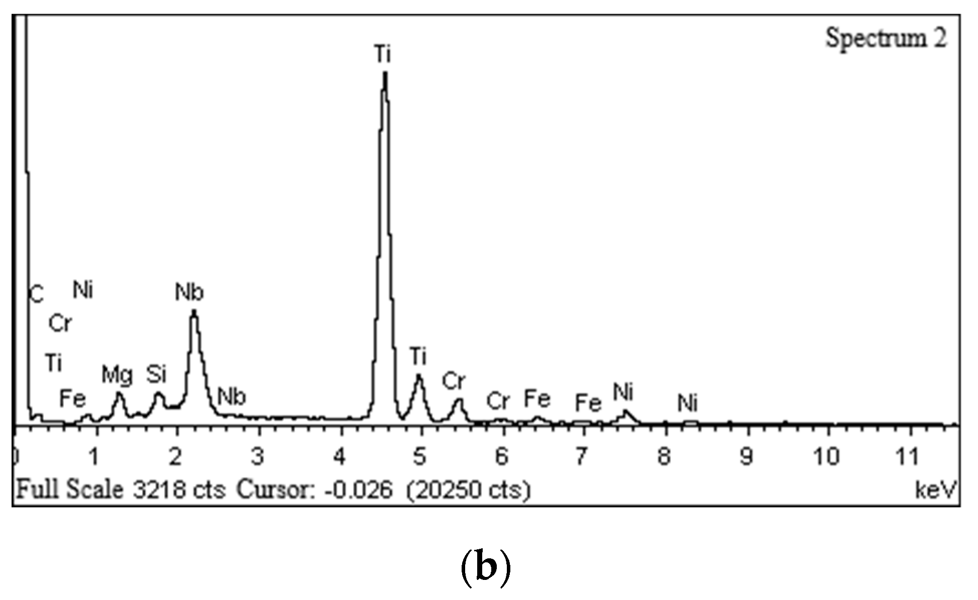
| Element | Wt. % | At % |
|---|---|---|
| O K | 10.37 | 28.42 |
| Al K | 2.79 | 4.54 |
| Si K | 1.16 | 1.81 |
| Ti K | 3.98 | 3.64 |
| Cr K | 33.47 | 28.23 |
| Fe K | 10.24 | 8.04 |
| Ni K | 26.85 | 20.06 |
| Nb L | 11.14 | 5.26 |
| Total | 100 | 100 |
Publisher’s Note: MDPI stays neutral with regard to jurisdictional claims in published maps and institutional affiliations. |
© 2022 by the authors. Licensee MDPI, Basel, Switzerland. This article is an open access article distributed under the terms and conditions of the Creative Commons Attribution (CC BY) license (https://creativecommons.org/licenses/by/4.0/).
Share and Cite
Xue, C.; Wang, D.; Zhang, J. Wear Mechanisms and Notch Formation of Whisker-Reinforced Alumina and Sialon Ceramic Tools during High-Speed Turning of Inconel 718. Materials 2022, 15, 3860. https://doi.org/10.3390/ma15113860
Xue C, Wang D, Zhang J. Wear Mechanisms and Notch Formation of Whisker-Reinforced Alumina and Sialon Ceramic Tools during High-Speed Turning of Inconel 718. Materials. 2022; 15(11):3860. https://doi.org/10.3390/ma15113860
Chicago/Turabian StyleXue, Chao, Dong Wang, and Jingjing Zhang. 2022. "Wear Mechanisms and Notch Formation of Whisker-Reinforced Alumina and Sialon Ceramic Tools during High-Speed Turning of Inconel 718" Materials 15, no. 11: 3860. https://doi.org/10.3390/ma15113860
APA StyleXue, C., Wang, D., & Zhang, J. (2022). Wear Mechanisms and Notch Formation of Whisker-Reinforced Alumina and Sialon Ceramic Tools during High-Speed Turning of Inconel 718. Materials, 15(11), 3860. https://doi.org/10.3390/ma15113860