
Requirements for Hybrid Technology Enabling the Production of High-Precision Thin-Wall Castings

Abstract
:1. Introduction
2. Materials and Methods
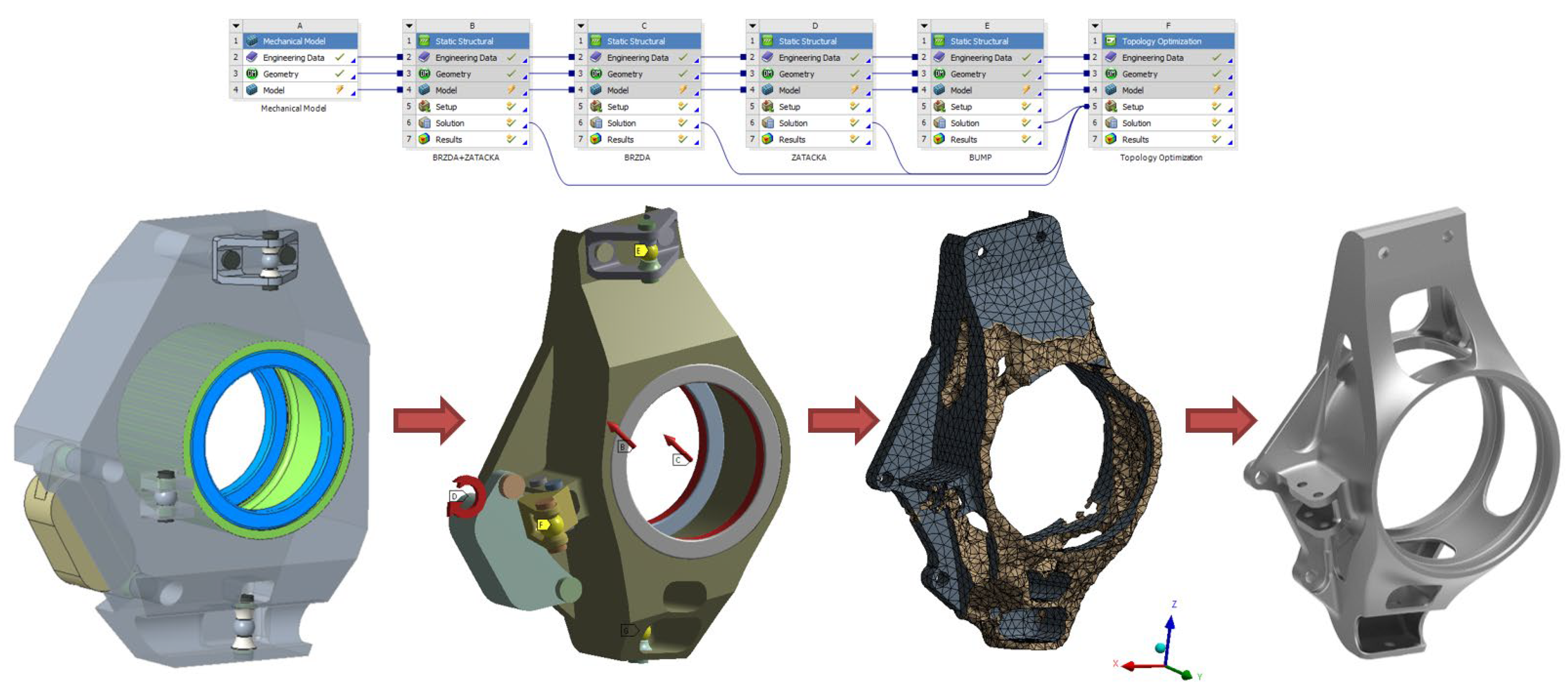
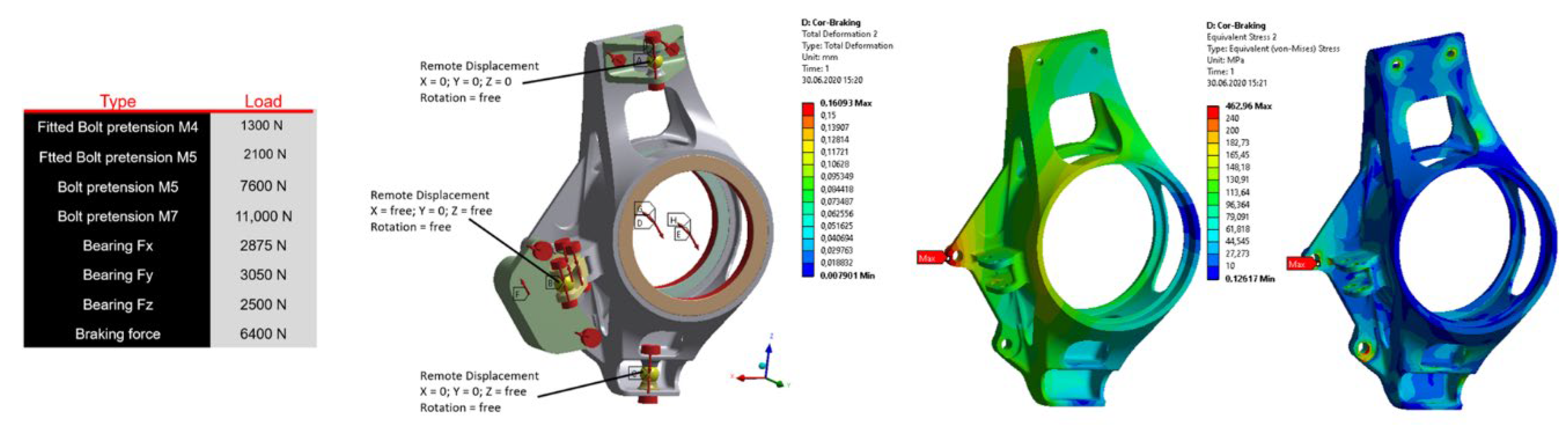
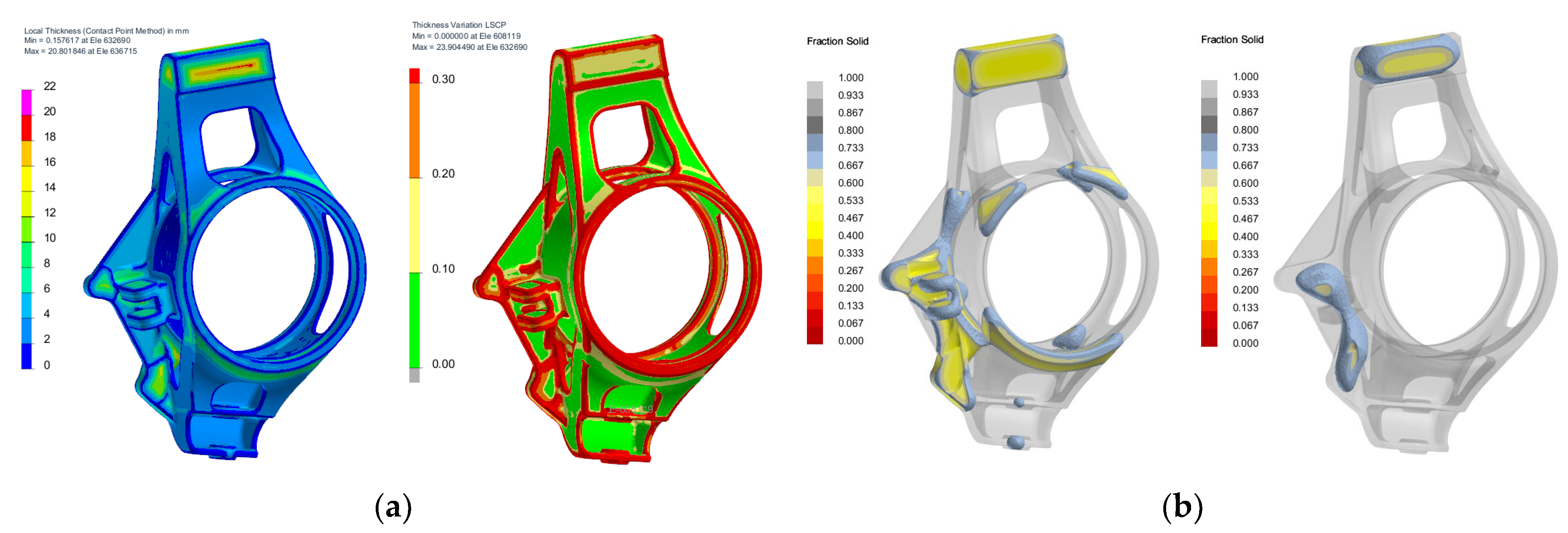
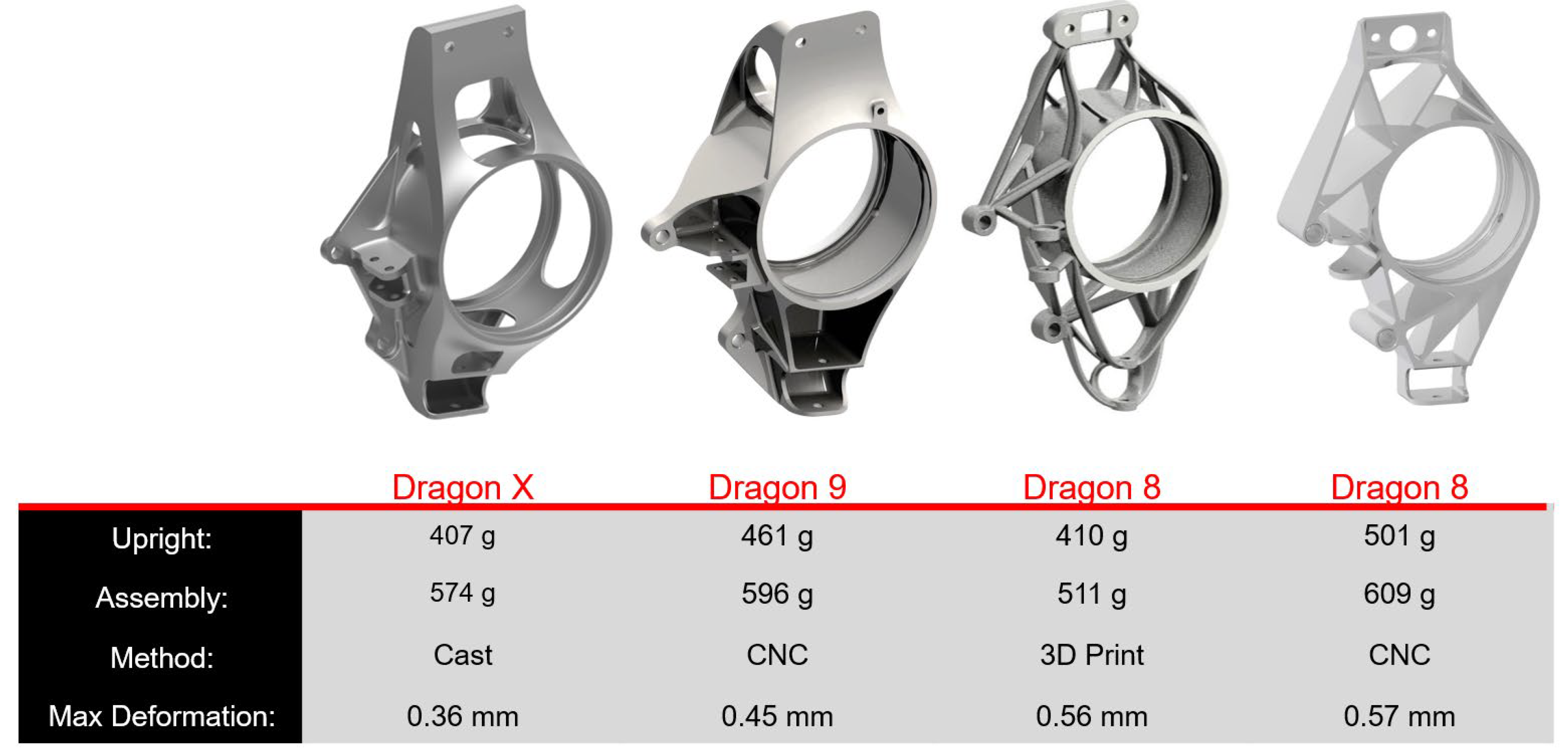
2.1. Topology Casting Optimization
2.2. Investment Casting Requirements
- Min. radius on the outer and inner edges 1 mm;
- The smallest theoretical wall thickness 0.8 mm (depends on the casting size and shape, material, temperature, etc.) and the common casting thickness is 2–4 mm;
- No draft angle has to be factored;
- Gradual wall transition towards feeding (directed solidification towards the gate);
- Use transition ribs for thin walls (increasing stiffness, metal flow, decreasing deformation);
- If possible, do not close the internal casting cavities (with regard to the drying of the ceramic layers and subsequent removal of the shell);
- With the 3D printed model, model the gates right away (better connection of the part to the gating system).
- High surface quality of the printed model (connected with the 3D print method and the possible surface finish);
- High dimensional accuracy of the printed model (affects the final dimensions of the casting);
- Low thermal expansion of the material (higher expansion causes the ceramic shell to crack when being fired);
- Low content of ash matter after the model burns (high content of ash matter requires long firing. High ash content may have a negative effect on the resulting surface quality of the casting).
3. Results
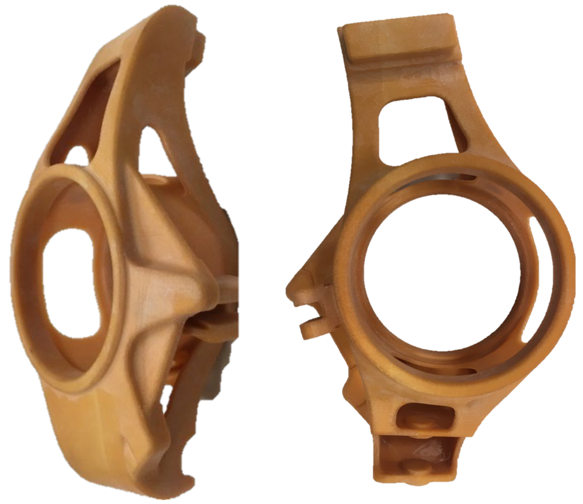
3.1. Properties of a Model Made by 3D Printing
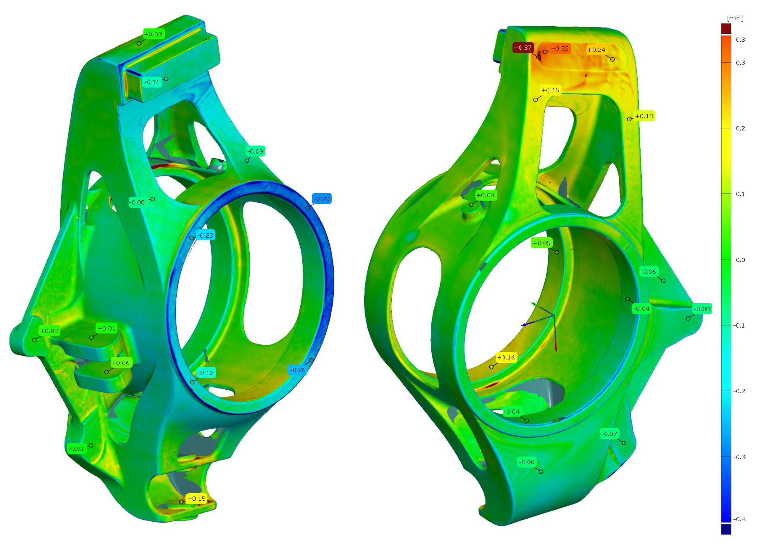
3.1.1. Assessment of Dimensional Changes in the Model
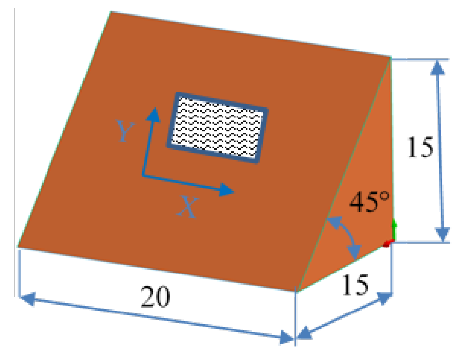
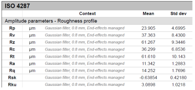
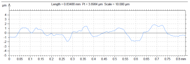
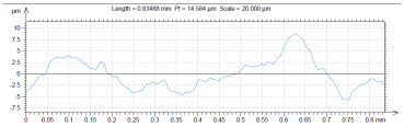
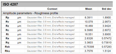
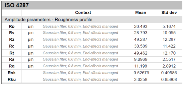
3.1.2. Assessment of Surface Roughness
4. Discussion
5. Conclusions
- Topological optimization of the casting design must be complemented by technological co-design to ensure that the design is technologically feasible.
- Due to its dimensional stability, the PMMA material is more accurate than standard wax models, which makes it possible to eliminate the use of levelling tools for complex shapes.
- The surface quality of the printed model is significantly lower in comparison to wax models produced by injection into metal molds. On the other hand, it still meets the needs of prototype castings. To improve the surface roughness, it would be necessary to increase the print resolution, which would require a change in the 3D printer or the printing technology. Another way is to adjust the infiltration process of the surface layer, either by repeated dipping into a wax suspension, or by adjusting its viscosity.
Author Contributions
Funding
Conflicts of Interest
References
- Campbell, J. Thin wall castings. Mater. Sci. Technol. 1988, 4, 194–204. [Google Scholar] [CrossRef]
- Halonen, A. Trends in Lightweighting with Metal Castings. Casting Source, May–June, 2020, 32. Available online: https://lightweighting.co/wp-content/uploads/2020/06/Trends-in-Lightweighting-with-Metal-Castings.pdf (accessed on 20 March 2022).
- Krutiš, V.; Šprta, P.; Kaňa, V.; Zadera, A.; Cileček, J. Integration of Virtual Engineering and Additive Manufacturing for Rapid Prototyping of Precision Castings. Arch. Foundry Eng. 2021, 21, 51–55. [Google Scholar] [CrossRef]
- Bralla, J.G. Design for Manufacturability Handbook, 2nd ed.; McGraweHill Handbooks: New York, NY, USA, 1999. [Google Scholar]
- Kumar, P.; Ahuja, I.P.S.; Singh, R. A Framework for Developing a Hybrid Investment Casting Process. Asian Rev. Mech. Eng. 2013, 2, 49–55. [Google Scholar]
- Pattnaik, S.; Karunakar, D.B.; Jha, P.K. Developments in investment casting process, A review. J. Mater. Process. Technol. 2012, 212, 2332–2348. [Google Scholar] [CrossRef]
- Mueller, T.J. What impact will 3D metal printing have on investment casting. In Transactions of the American Foundry Society, One Hundred Twenty-Second Annual Metalcasting Congress; American Foundry Society: Schaumburg, IL, USA, 2018; pp. 305–310. ISBN 978-0-87433-464-7. [Google Scholar]
- Greenbaum, P.Y.; Khan, S. Direct investment casting of rapid prototype parts: Practical commercial experience. In Proceedings of the 2nd European Conference on Rapid Prototyping, Nottingham, UK, 15–16 July 1993; pp. 77–93. [Google Scholar]
- Mukhtarkhanov, M.; Perveen, A.; Talamona, D. Application of Stereolithography Based 3D Printing Technology in Investment Casting. Micromachines 2020, 11, 946. [Google Scholar] [CrossRef] [PubMed]
- Kumar, P.; Ahuja, I.P.S.; Singh, R. Application of fusion deposition modelling for rapid investment casting—A review. Int. J. Mater. Eng. Innov. 2012, 3, 204–227. [Google Scholar] [CrossRef]
- Carneiro, V.H.; Rawson, S.D.; Puga, H.; Meireles, J.; Withers, P.J. Additive Manufacturing Assisted Investment Casting: A Low-Cost Method to Fabricate Periodic Metallic Cellular Lattices. Addit. Manuf. 2020, 33, 101085. [Google Scholar] [CrossRef]
- Chohan, J.S.; Singh, R.; Boparai, K.S. Vapor smoothing process for surface finishing of FDM replicas. Mater. Today Proc. 2020, 26, 173–179. [Google Scholar] [CrossRef]
- Cheah, C.M.; Chua, C.K.; Lee, C.W.; Feng, C.; Totong, K. Rapid prototyping and tooling techniques: A review of applications for rapid investment casting. Int. J. Adv. Manuf. Technol. 2005, 25, 308–320. [Google Scholar] [CrossRef]
- Chen, X.; Li, D.; Wu, H.; Tang, Y.; Zhao, L. Analysis of ceramic shell cracking in stereolithography-based rapid casting of turbine blade. Int. J. Adv. Manuf. Technol. 2011, 55, 447–455. [Google Scholar] [CrossRef]
- Note, Investment Casting with PolyCast TM. Available online: https://polymaker.com/Downloads/Application_Note/PolyCast_Application_Note_V1.pdf (accessed on 8 March 2022).
- Why PMMA 3D Printing for Investment Casting is the Future. Available online: https://www.voxeljet.com/3d-printing-solution/investment-casting/#anchor-2 (accessed on 7 March 2022).
- Doležal, T. Těhlice Formulového Vozu z Hliníkové Slitiny. Bachelor’s Thesis, Brno University of Technology, Faculty of Mechanical Engineering, Brno, Czech Republic, 2020. [Google Scholar]
- Beeley, P.R.; Smart, R.F. Investment Casting, 1st ed.; The Institute of Materials, The University Press Cambridge: Cambridge, UK, 1995; p. 486. [Google Scholar]
- Horáček, M. Accuracy of castings manufactured by the lost wax process. Foundry Trade J. 1997, 171, 424–429. [Google Scholar]
- Voight, R.C. Factors Influencing the Dimensional Variability of Investment Castings. In Proceedings of the 45th Technical Meeting of the Investment Casting Institute, Dallas, TX, USA; 1997; pp. 42–60. [Google Scholar]
- Jacobs, P. QuickCast 1.1 & Rapid Tooling. In Proceedings of the NASUG 1995 Annual Meeting and Conference, Tampa, FL, USA, 4–7 June 1995. [Google Scholar]
- Moylan, J. Considerations for Measuring Glass Transition Temperature. Available online: https://www.element.com/nucleus/2017/08/15/18/45/considerations-for-measuring-glass-transition-temperature (accessed on 7 March 2022).
- Polymaker. PolyCast Data Sheet. Available online: https://filament2print.com/gb/index.php?controller=attachment&id_attachment=313 (accessed on 3 March 2022).


| Sample A | Sample B |
|---|---|
| Wax model − metal die | 3D printed model − PMMA (binder jetting) |
| 3D model of the sample structure | 3D model of the sample structure |
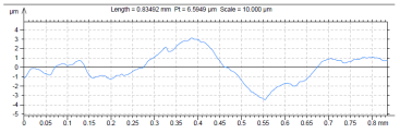
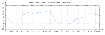
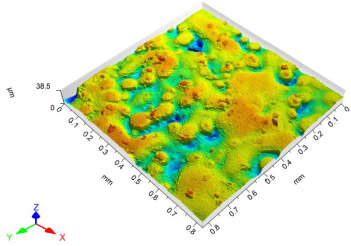 |  |
| Basic profile along the X axis | Basic profile along the X axis |
 |  |
| Roughness parameters along the X axis | Roughness parameters along the X axis |
 |  |
| Basic profile along the Y axis | Basic profile along the Y axis |
 |  |
| Roughness parameters along the Y axis | Roughness parameters along the Y axis |
 |  |
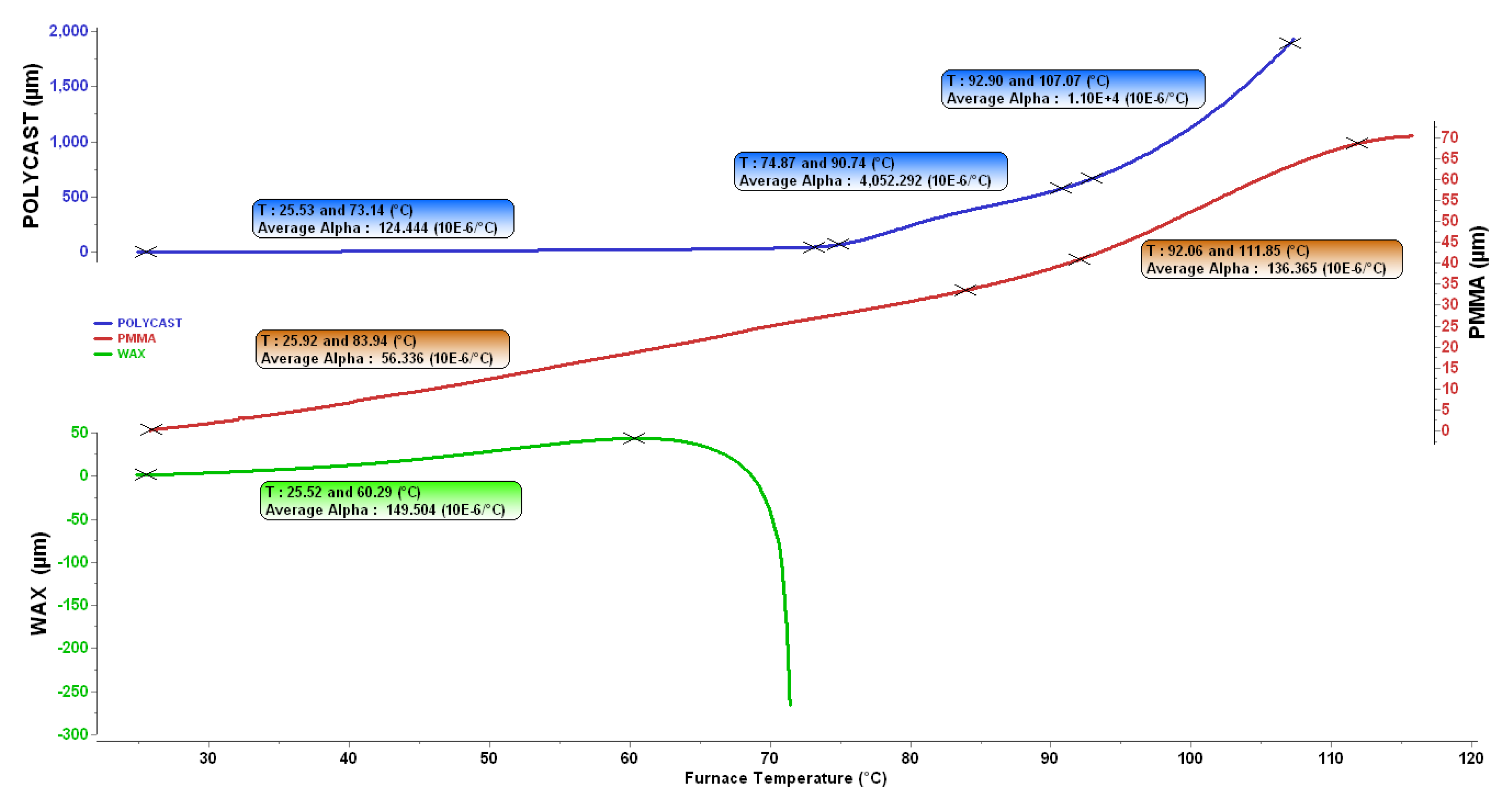
| Material | Temperature Interval [°C] | Thermal Expansion Coeff. [10−6/°C] | Tg [°C] |
|---|---|---|---|
| PMMA (BJ) | 25.92–83.94 | 56.34 | 92 |
| 92.06–111.85 | 136.37 | ||
| WAX | 25.52–60.29 | 149.51 | - |
| Polycast ™ (FDM filament) | 25.53–73.14 | 124.44 | 75 |
| 74.87–90.74 | 4052 | ||
| 92.9–107.07 | 11000 |
Publisher’s Note: MDPI stays neutral with regard to jurisdictional claims in published maps and institutional affiliations. |
© 2022 by the authors. Licensee MDPI, Basel, Switzerland. This article is an open access article distributed under the terms and conditions of the Creative Commons Attribution (CC BY) license (https://creativecommons.org/licenses/by/4.0/).
Share and Cite
Krutiš, V.; Novosad, P.; Záděra, A.; Kaňa, V. Requirements for Hybrid Technology Enabling the Production of High-Precision Thin-Wall Castings. Materials 2022, 15, 3805. https://doi.org/10.3390/ma15113805
Krutiš V, Novosad P, Záděra A, Kaňa V. Requirements for Hybrid Technology Enabling the Production of High-Precision Thin-Wall Castings. Materials. 2022; 15(11):3805. https://doi.org/10.3390/ma15113805
Chicago/Turabian StyleKrutiš, Vladimír, Pavel Novosad, Antonín Záděra, and Václav Kaňa. 2022. "Requirements for Hybrid Technology Enabling the Production of High-Precision Thin-Wall Castings" Materials 15, no. 11: 3805. https://doi.org/10.3390/ma15113805
APA StyleKrutiš, V., Novosad, P., Záděra, A., & Kaňa, V. (2022). Requirements for Hybrid Technology Enabling the Production of High-Precision Thin-Wall Castings. Materials, 15(11), 3805. https://doi.org/10.3390/ma15113805