
Surface Topographic Features after Milling of Additively Manufactured AlSi10Mg Aluminum Alloy


Abstract
:1. Introduction
2. Materials and Methods
3. Results and Discussion
4. Conclusions
Author Contributions
Funding
Institutional Review Board Statement
Informed Consent Statement
Data Availability Statement
Acknowledgments
Conflicts of Interest
References
- Struzikiewicz, G.; Zȩbala, W.; Matras, A.; Machno, M.; Ślusarczyk, Ł.; Hichert, S.; Laufer, F. Turning research of additive laser molten stainless steel 316L obtained by 3D printing. Materials 2019, 12, 182. [Google Scholar] [CrossRef] [PubMed] [Green Version]
- Gong, H.; Rafi, K.; Gu, H.; Starr, T.; Stucker, B. Analysis of defect generation in Ti–6Al–4V parts made using powder bed fusion additive manufacturing processes. Addit. Manuf. 2014, 1–4, 87–98. [Google Scholar] [CrossRef]
- Niaki, M.K.; Torabi, S.A.; Nonino, F. Why manufacturers adopt additive manufacturing technologies: The role of sustainability. J. Clean. Prod. 2019, 222, 381–392. [Google Scholar] [CrossRef]
- Krawczyk, M.; Królikowski, M.; Grochała, D.; Powałka, B.; Figiel, P.; Wojciechowski, S. Evaluation of Surface Topography after Face Turning of CoCr Alloys Fabricated by Casting and Selective Laser Melting. Materials 2020, 13, 2448. [Google Scholar] [CrossRef]
- Hung, W. Postprocessing of Additively Manufactured Metal Parts. J. Mater. Eng. Perform. 2021, 30, 6439–6460. [Google Scholar] [CrossRef]
- Beitz, S.; Uerlich, R.; Bokelmann, T.; Diener, A.; Vietor, T.; Kwade, A. Influence of Powder Deposition on Powder Bed and Specimen Properties. Materials 2019, 12, 297. [Google Scholar] [CrossRef] [Green Version]
- Bai, S.; Perevoshchikova, N.; Sha, Y.; Wu, X. The Effects of Selective Laser Melting Process Parameters on Relative Density of the AlSi10Mg Parts and Suitable Procedures of the Archimedes Method. Appl. Sci. 2019, 9, 583. [Google Scholar] [CrossRef] [Green Version]
- Khairallah, S.A.; Anderson, A.T.; Rubenchik, A.; King, W.E. Laser powder-bed fusion additive manufacturing: Physics of complex melt flow and formation mechanisms of pores, spatter, and denudation zones. Acta Mater. 2016, 108, 36–45. [Google Scholar] [CrossRef] [Green Version]
- Kabir, M.R.; Richter, H. Modeling of Processing-Induced Pore Morphology in an Additively-Manufactured Ti-6Al-4V Alloy. Materials 2017, 10, 145. [Google Scholar] [CrossRef] [Green Version]
- Teng, C.; Pal, D.; Gong, H.; Zeng, K.; Briggs, K.; Patil, N.; Stucker, B. A review of defect modeling in laser material processing. Addit. Manuf. 2017, 14, 137–147. [Google Scholar]
- Wei, P.; Wei, Z.; Chen, Z.; Du, J.; He, Y.; Li, J.; Zhou, Y. The AlSi10Mg samples produced by selective laser melting: Single track, densification, microstructure and mechanical behavior. Appl. Surf. Sci. 2017, 408, 38–50. [Google Scholar] [CrossRef]
- Wang, L.; Wang, S.; Wu, J. Experimental investigation on densification behavior and surface roughness of AlSi10Mg powders produced by selective laser melting. Opt. Laser Technol. 2017, 96, 88–96. [Google Scholar] [CrossRef]
- Maamoun, A.H.; Xue, Y.F.; Elbestawi, M.A.; Veldhuis, S.C. The Effect of Selective Laser Melting Process Parameters on the Microstructure and Mechanical Properties of Al6061 and AlSi10Mg Alloys. Materials 2019, 12, 12. [Google Scholar] [CrossRef] [Green Version]
- Trevisan, F.; Calignano, F.; Lorusso, M.; Pakkanen, J.; Aversa, A.; Ambrosio, E.P.; Lombardi, M.; Fino, P.; Manfredi, D. On the Selective Laser Melting (SLM) of the AlSi10Mg Alloy: Process, Microstructure, and Mechanical Properties. Materials 2017, 10, 76. [Google Scholar] [CrossRef] [Green Version]
- Gao, Y.; Zhao, J.; Zhao, Y.; Wang, Z.; Song, H.; Gao, M. Effect of processing parameters on solidification defects behavior of laser deposited AlSi10Mg alloy. Vacuum 2019, 167, 471–478. [Google Scholar] [CrossRef]
- Kaynak, Y.; Kitay, O. The effect of post-processing operations on surface characteristics of 316L stainless steel produced by selective laser melting. Addit. Manuf. 2019, 26, 84–93. [Google Scholar] [CrossRef]
- Yassin, A.; Ueda, T.; Furumoto, T.; Hosokawa, A.; Tanaka, R.; Abe, S. Experimental investigation on cutting mechanism of laser sintered material using small ball end mill. J. Mater. Process. Technol. 2009, 209, 5680–5689. [Google Scholar] [CrossRef]
- Milton, S.; Morandeau, A.; Chalon, F.; Leroy, R. Influence of Finish Machining on the Surface Integrity of Ti6Al4V Produced by Selective Laser Melting. Procedia CIRP 2016, 45, 127–130. [Google Scholar] [CrossRef] [Green Version]
- Struzikiewicz, G.; Zębala, W.; Słodki, B. Cutting parameters selection for sintered alloy AlSi10Mg longitudinal turning. Measurement 2019, 138, 39–53. [Google Scholar] [CrossRef]
- Dumas, M.; Cabanettes, F.; Kaminski, R.; Valiorgue, F.; Picot, E.; Lefebvre, F.; Grosjean, C.; Rech, J. Influence of the finish cutting operations on the fatigue performance of Ti-6Al-4V parts produced by Selective Laser Melting. Procedia CIRP 2018, 71, 429–434. [Google Scholar] [CrossRef]
- Jiang, X.; Senin, N.; Scott, P.J.; Blateyron, F. Feature-based characterisation of surface topography and its application. CIRP Ann. 2021, 70, 681–702. [Google Scholar]
- Pawlus, P.; Reizer, R.; Wieczorowski, M. Functional Importance of Surface Texture Parameters. Materials 2021, 14, 5326. [Google Scholar] [CrossRef]
- Whitehouse, D.J. Handbook of Surface and Nanometrology; CRC Press: Boca Raton, FL, USA, 2011. [Google Scholar]
- Liang, X.; Liu, Z.; Wanga, B. State-of-the-art of surface integrity induced by tool wear effects in machining process of titanium and nickel alloys: A review. Measurement 2019, 132, 150–181. [Google Scholar]
- Ereifej, N.S.; Oweis, Y.G.; Eliades, G. The effect of polishing technique on 3-D surface roughness and gloss of dental restorative resin composites. Oper. Dent. 2013, 38, E9–E20. [Google Scholar] [CrossRef] [Green Version]
- Lenart, A.; Pawlus, P.; Dzierwa, A.; Wos, S.; Reizer, R. The effect of surface texture on lubricated fretting. Materials 2020, 13, 4886. [Google Scholar] [CrossRef]
- Świrad, S.; Wydrzynski, D.; Niesłony, P.; Krolczyk, G.M. Influence of hydrostatic burnishing strategy on the surface topography of martensitic steel. Measurement 2019, 138, 590–601. [Google Scholar] [CrossRef]
- Mezari, R.A.; Pereira, R.S.F.; Sousa, F.J.P.; Weingaertner, W.L.; Fredel, M.C. Wear mechanism and morphologic space in ceramic honing process. Wear 2016, 362–363, 33–38. [Google Scholar] [CrossRef]
- Belhadjamor, M.; Belghith, S.; Mezlini, S.; El Mansori, M. Numerical study of normal contact stiffness, non-Gaussian roughness and elastic contact behavior. Proc. Inst. Mech. Eng. Part J J. Eng. Tribol. 2020, 234, 1368–1380. [Google Scholar] [CrossRef]
- Etsion, I. State of the art in laser surface texturing. J. Tribol. ASME 2005, 127, 248–253. [Google Scholar] [CrossRef]
- Gachot, C.; Rosenkranz, A.; Hsu, S.M.; Costa, H.L. A critical assessment of surface texturing for friction and wear improvement. Wear 2017, 372–373, 21–41. [Google Scholar]
- Sharma, S.; Jamwal, G.; Awasthi, R.K. Enhancement of steady state performance of hydrodynamic journal bearing using chevron-shaped surface texture. Proc. Inst. Mech. Eng. Part J J. Eng. Tribol. 2019, 233, 1833–1843. [Google Scholar] [CrossRef]
- Morris, N.; Rahmani, R.; Rahnejat, H.; King, P.D.; Howell-Smith, S. A Numerical Model to Study the Role of Surface Textures at Top Dead Center Reversal in the Piston Ring to Cylinder Liner Contact. J. Tribol. 2016, 138, 021703. [Google Scholar] [CrossRef] [Green Version]
- Grabon, W.; Pawlus, P.; Koszela, W.; Reizer, R. Proposals of methods of oil capacity calculation. Tribol. Int. 2014, 75, 117–122. [Google Scholar] [CrossRef]
- Fecske, S.K.; Gkagkas, K.; Gachot, C.; Vernes, A. Interdependence of Amplitude Roughness Parameters on Rough Gaussian Surfaces. Tribol. Lett. 2020, 68, 43. [Google Scholar] [CrossRef]
- Hu, S.; Reddyhoff, T.; Wen, J.; Huang, W.; Shi, X.; Dini, D.; Peng, Z. Characterization and simulation of bi-Gaussian surfaces induced by material transfer and additive processes. Tribol. Int. 2019, 136, 31–44. [Google Scholar] [CrossRef]
- ISO 25178-2:2012; Geometrical Product Specifications (GPS)—Surface Texture: Areal—Part 2: Terms, Definitions and Surface Texture Parameters. International Organization for Standarization: Geneva, Switzerland, 2012. Available online: https://www.iso.org/standard/42785.html (accessed on 15 April 2022).
- Tian, Y.; Wang, J.; Peng, Z.; Jiang, X. A new approach to numerical characterisation of wear particle surfaces in three-dimensions for wear study. Wear 2012, 282–283, 59–68. [Google Scholar] [CrossRef] [Green Version]
- Ye, R.; Jiang, X.; Blunt, L.; Cui, C.; Yu, Q. The application of 3D-motif analysis to characterize diamond grinding wheel topography. Measurement 2016, 77, 73–79. [Google Scholar] [CrossRef]
- Lou, S.; Pagani, L.; Zeng, W.; Jiang, X.; Scott, P.J. Watershed segmentation of topographical features on freeform surfaces and its application to additively manufactured surfaces. Precis. Eng. 2020, 63, 177–186. [Google Scholar] [CrossRef]
- Struzikiewicz, G.; Sioma, A. Evaluation of surface roughness and defect formation after the machining of sintered aluminum alloy AlSi10Mg. Materials 2020, 13, 1662. [Google Scholar] [CrossRef] [Green Version]
- Yadav, R.N. A hybrid approach of Taguchi-Response Surface Methodology for modeling and optimization of Duplex Turning process. Measurement 2017, 100, 131–138. [Google Scholar] [CrossRef]
- Kempen, K.; Thijs, L.; Van Humbeeck, J.; Kruth, J.P. Mechanical properties of AlSi10Mg produced by Selective Laser Melting. Phys. Procedia 2012, 39, 439–446. [Google Scholar] [CrossRef] [Green Version]
- Read, N.; Wang, W.; Essa, K.; Attallah, M.M. Selective laser melting of AlSi10Mg alloy: Process optimisation and mechanical properties development. Mater. Des. 2015, 65, 417–424. [Google Scholar] [CrossRef] [Green Version]


| No. | A | B | f (mm/Tooth) | Milling |
|---|---|---|---|---|
| 1 | 1 | 1 | 0.050 | down |
| 2 | 1 | 2 | 0.050 | up |
| 3 | 2 | 1 | 0.033 | down |
| 4 | 2 | 2 | 0.033 | up |
| 5 | 3 | 1 | 0.025 | down |
| 6 | 3 | 2 | 0.025 | up |
| 7 | 4 | 1 | 0.013 | down |
| 8 | 4 | 2 | 0.013 | up |
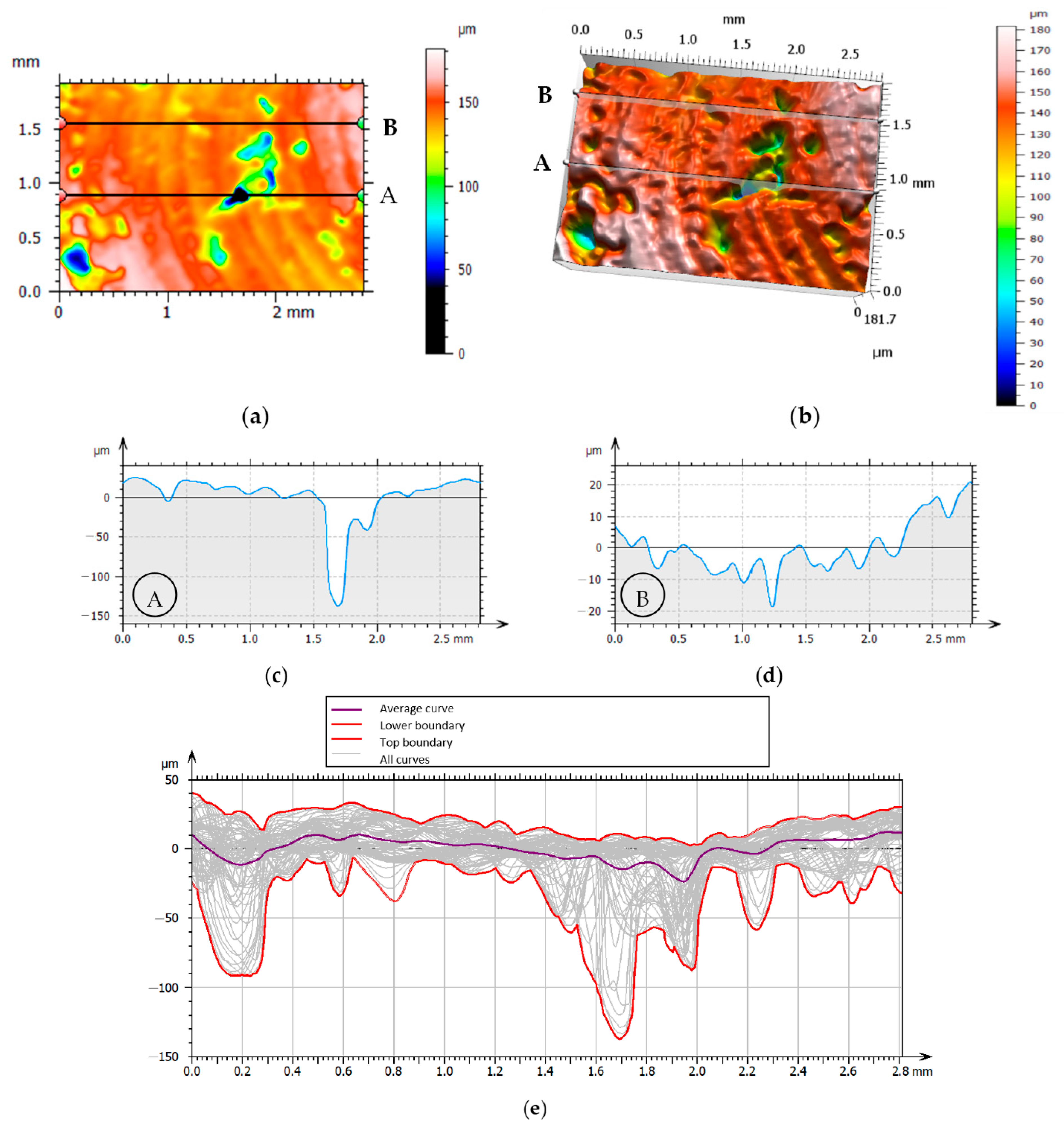
| Profile A | Profile B | ||||
|---|---|---|---|---|---|
| Rp | 21.68 | µm | Rp | 4.37 | µm |
| Rv | 33.69 | µm | Rv | 7.39 | µm |
| Rz | 55.37 | µm | Rz | 11.76 | µm |
| Rt | 112.0 | µm | Rt | 16.47 | µm |
| Ra | 10.92 | µm | Ra | 2.49 | µm |
| No. | f | Milling | Sa | Sz | Sq | Sku | Sp | Sv | Sk | Spk | Svk | Smrk1 | Smrk2 | Sak1 | Sak2 | Vmp | Vmc | Vvc | Vvv | Spd | Spc | S5v | Sda | Sdv |
|---|---|---|---|---|---|---|---|---|---|---|---|---|---|---|---|---|---|---|---|---|---|---|---|---|
| mm/ tooth | µm | µm | µm | µm | µm | µm | µm | µm | µm | % | % | mm3/mm2 | mm3/mm2 | mm3/mm2 | mm3/mm2 | mm3/mm2 | mm3/mm2 | 1/ mm2 | 1/mm | µm | mm2 | mm3 | ||
| 1 | 0.050 | Down | 19.16 | 220.51 | 27.96 | 7.61 | 73.63 | 146.88 | 46.59 | 18.92 | 63.14 | 13.39 | 86.13 | 0.0013 | 0.0044 | 0.0009 | 0.0172 | 0.0246 | 0.0057 | 2.12 | 26.47 | 120.56 | 0.150 | 0.00033 |
| 2 | 0.050 | Up | 16.25 | 235.77 | 24.34 | 11.03 | 71.98 | 163.79 | 34.69 | 34.09 | 48.67 | 20.72 | 90.15 | 0.0035 | 0.0024 | 0.0012 | 0.0157 | 0.0290 | 0.0032 | 1.61 | 27.25 | 125.58 | 0.162 | 0.00043 |
| 3 | 0.033 | Down | 13.94 | 189.10 | 21.55 | 14.40 | 29.31 | 159.79 | 18.69 | 4.61 | 51.75 | 6.19 | 75.35 | 0.0001 | 0.0064 | 0.0003 | 0.0118 | 0.0098 | 0.0054 | 2.38 | 47.58 | 118.85 | 0.150 | 0.00052 |
| 4 | 0.033 | Up | 11.44 | 123.38 | 14.89 | 3.98 | 49.68 | 73.70 | 27.39 | 20.14 | 20.40 | 21.74 | 91.70 | 0.0022 | 0.0008 | 0.0007 | 0.0115 | 0.0206 | 0.0016 | 3.00 | 22.24 | 63.58 | 0.125 | 0.00022 |
| 5 | 0.025 | Down | 11.35 | 181.66 | 18.02 | 13.21 | 40.26 | 141.40 | 23.79 | 11.11 | 44.00 | 17.78 | 85.50 | 0.0010 | 0.0032 | 0.0004 | 0.0097 | 0.0144 | 0.0038 | 1.85 | 23.97 | 95.99 | 0.168 | 0.00051 |
| 6 | 0.025 | Up | 8.55 | 179.07 | 12.98 | 28.18 | 34.81 | 144.25 | 25.38 | 10.11 | 31.88 | 11.33 | 93.25 | 0.0006 | 0.0011 | 0.0005 | 0.0088 | 0.0124 | 0.0017 | 0.73 | 297.30 | 80.79 | 0.129 | 0.00052 |
| 7 | 0.013 | Down | 9.61 | 106.90 | 12.51 | 5.07 | 39.73 | 67.17 | 30.47 | 10.15 | 19.19 | 6.49 | 89.94 | 0.0003 | 0.0010 | 0.0005 | 0.0109 | 0.0132 | 0.0017 | 1.45 | 14.09 | 56.58 | 0.124 | 0.00031 |
| 8 | 0.013 | Up | 9.75 | 196.23 | 14.71 | 12.94 | 71.85 | 124.38 | 23.24 | 13.83 | 33.06 | 16.70 | 88.77 | 0.0012 | 0.0019 | 0.0006 | 0.0087 | 0.0142 | 0.0025 | 1.24 | 139.77 | 92.81 | 0.123 | 0.00024 |
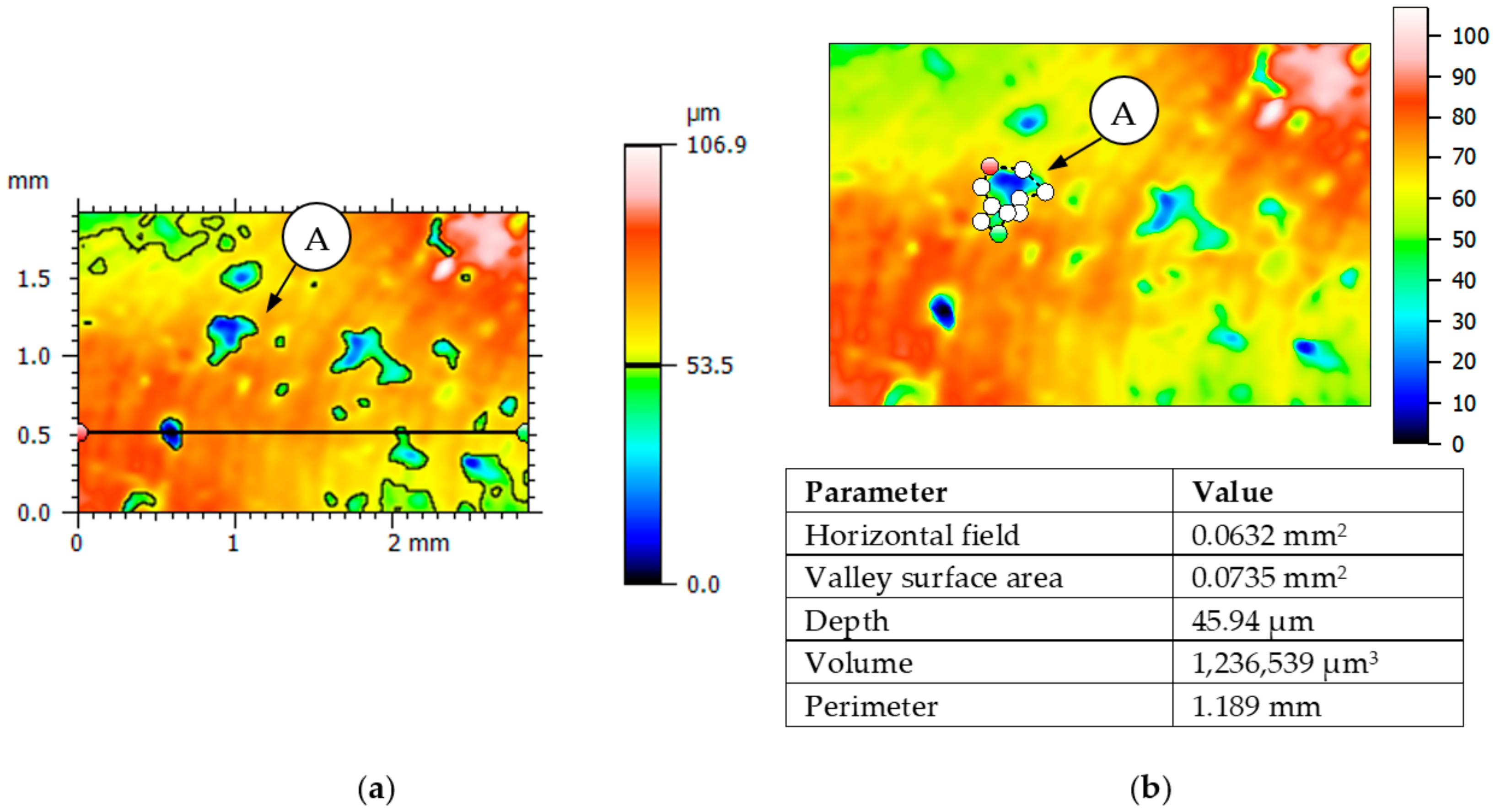
| Parameter | Result 1 | Result 2 | Result 3 | Average Value |
|---|---|---|---|---|
| Sq µm | 2.77 | 3.47 | 3.12 | 3.12 |
| Ssk | −0.285 | −0.0392 | −0.159 | −0.161 |
| Sku | 3.95 | 3.51 | 4.14 | 3.87 |
| Sp µm | 9.4 | 13.3 | 16 | 12.9 |
| Sv µm | 16.6 | 14.3 | 18 | 16.3 |
| Sz µm | 26 | 27.6 | 34 | 29.2 |
| Sa µm | 2.16 | 2.7 | 2.42 | 2.43 |
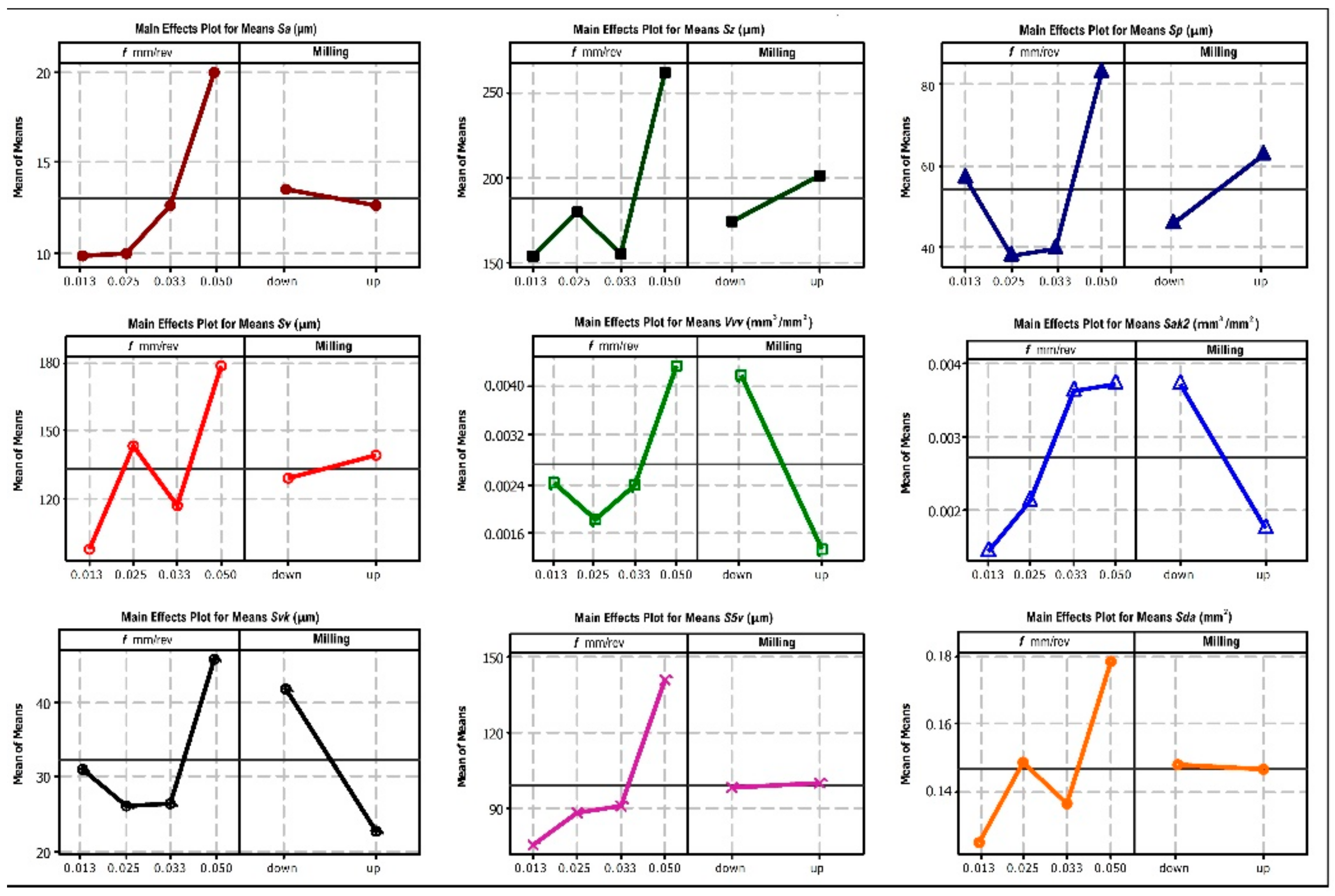
| Source | DF | Seq SS | Adj SS | Adj MS | F | P | Seq SS | Adj SS | Adj MS | F | P |
|---|---|---|---|---|---|---|---|---|---|---|---|
| Sa (µm) | Sz (µm) | ||||||||||
| A | 3 | 137.18 | 137.18 | 45.73 | 20.5 | 0.017 | 15231 | 15231 | 5077 | 1.79 | 0.322 |
| B | 1 | 1.46 | 1.46 | 1.46 | 0.65 | 0.478 | 1418 | 1418 | 1418 | 0.5 | 0.53 |
| Residual Error | 3 | 6.69 | 6.69 | 2.23 | 8489 | 8489 | 2830 | ||||
| Total | 7 | 145.34 | 25138 | ||||||||
| Sp (µm) | Sv (µm) | ||||||||||
| A | 3 | 2664.9 | 2664.9 | 888.3 | 6.85 | 0.074 | 7379.1 | 7379.1 | 2459.7 | 1.01 | 0.498 |
| B | 1 | 555.5 | 555.5 | 555.5 | 4.28 | 0.13 | 198.6 | 198.6 | 198.6 | 0.08 | 0.794 |
| Residual Error | 3 | 389 | 389 | 129.7 | 7338.4 | 7338.4 | 2446.1 | ||||
| Total | 7 | 3609.4 | 14916 | ||||||||
| Vvv (mm3/mm2) | Sak2 (mm3/mm2) | ||||||||||
| A | 3 | 0.000003 | 0.000003 | 0.000001 | 0.27 | 0.846 | 0.000008 | 0.000008 | 0.000003 | 0.7 | 0.61 |
| B | 1 | 0.000006 | 0.000006 | 0.000006 | 1.83 | 0.269 | 0.000008 | 0.000008 | 0.000008 | 2.23 | 0.232 |
| Residual Error | 3 | 0.000010 | 0.00001 | 0.000003 | 0.000011 | 0.000011 | 0.000004 | ||||
| Total | 7 | 0.000019 | 0.000027 | ||||||||
| Svk (µm) | S5v (µm) | ||||||||||
| A | 3 | 519.2 | 519.2 | 173.1 | 0.42 | 0.751 | 4901.99 | 4901.99 | 1634 | 1.54 | 0.366 |
| B | 1 | 731.7 | 731.7 | 731.7 | 1.79 | 0.273 | 7.57 | 7.57 | 7.57 | 0.01 | 0.938 |
| Residual Error | 3 | 1226.5 | 1226.5 | 408.8 | 3182.79 | 3182.79 | 1060.93 | ||||
| Total | 7 | 2477.4 | 8092.35 | ||||||||
| Sda (mm2) | |||||||||||
| A | 3 | 0.0032 | 0.0032 | 0.0011 | 1.26 | 0.428 | |||||
| B | 1 | 0.0000 | 0.0000 | 0.0000 | 0 | 0.959 | |||||
| Residual Error | 3 | 0.0025 | 0.0025 | 0.0008 | |||||||
| Total | 7 | 0.0057 | |||||||||
Publisher’s Note: MDPI stays neutral with regard to jurisdictional claims in published maps and institutional affiliations. |
© 2022 by the authors. Licensee MDPI, Basel, Switzerland. This article is an open access article distributed under the terms and conditions of the Creative Commons Attribution (CC BY) license (https://creativecommons.org/licenses/by/4.0/).
Share and Cite
Struzikiewicz, G.; Sioma, A. Surface Topographic Features after Milling of Additively Manufactured AlSi10Mg Aluminum Alloy. Materials 2022, 15, 3604. https://doi.org/10.3390/ma15103604
Struzikiewicz G, Sioma A. Surface Topographic Features after Milling of Additively Manufactured AlSi10Mg Aluminum Alloy. Materials. 2022; 15(10):3604. https://doi.org/10.3390/ma15103604
Chicago/Turabian StyleStruzikiewicz, Grzegorz, and Andrzej Sioma. 2022. "Surface Topographic Features after Milling of Additively Manufactured AlSi10Mg Aluminum Alloy" Materials 15, no. 10: 3604. https://doi.org/10.3390/ma15103604
APA StyleStruzikiewicz, G., & Sioma, A. (2022). Surface Topographic Features after Milling of Additively Manufactured AlSi10Mg Aluminum Alloy. Materials, 15(10), 3604. https://doi.org/10.3390/ma15103604