
Preparation and Performance of Mo/Cu/Fe Multi-Layer Composite Coating with Staggered Spatial Structure by Electro-Explosive Spraying Technology


Abstract
:1. Introduction
2. Coating System Design
3. Experimental Equipment, Materials and Methods
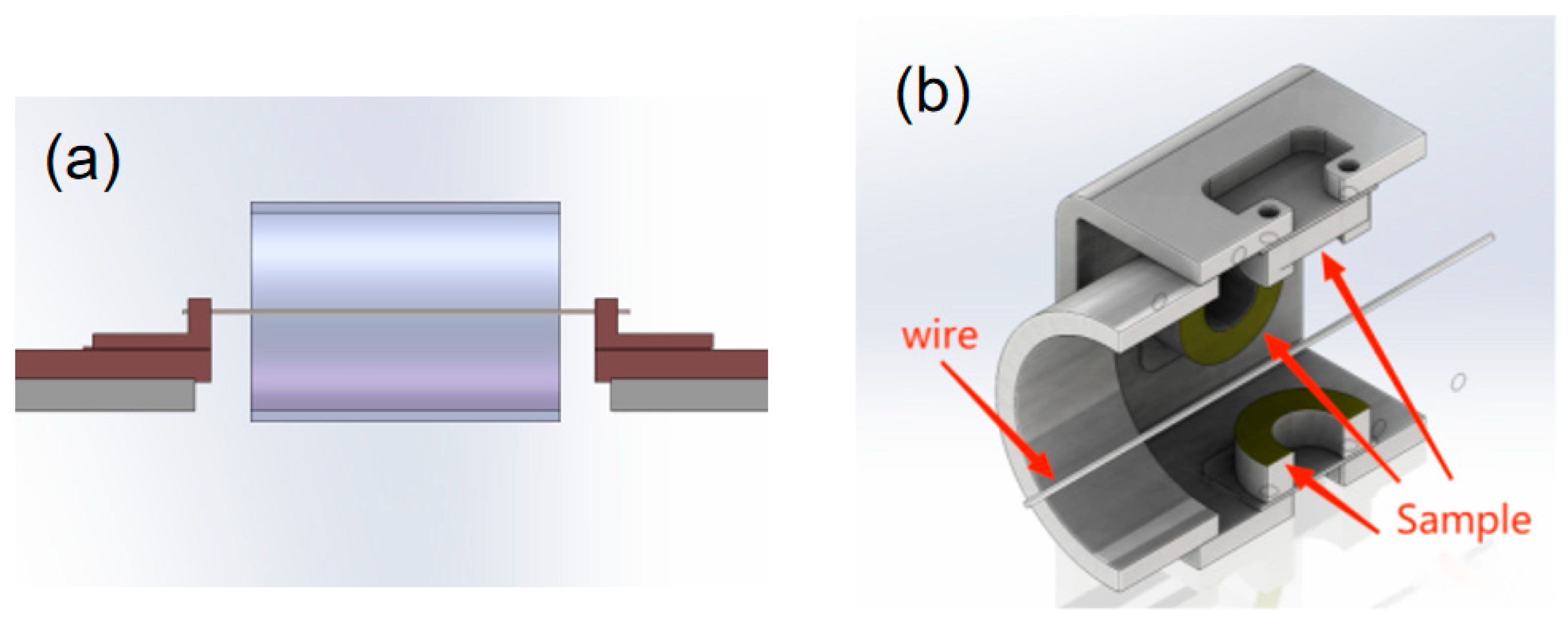
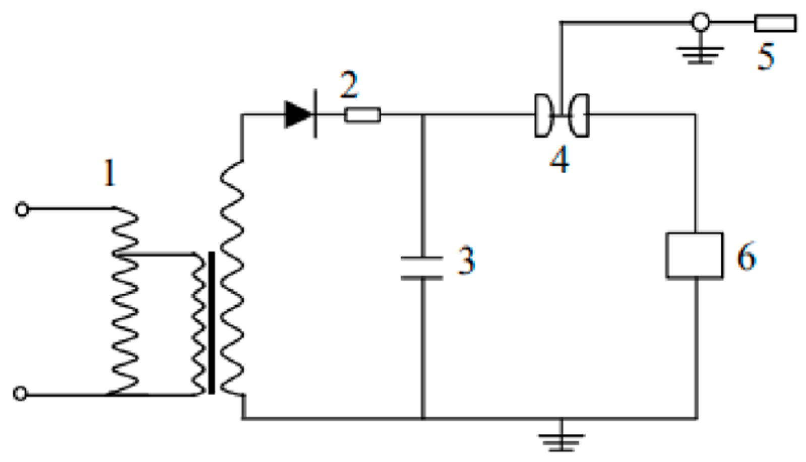
3.1. Electro-Explosive Spraying Equipment
3.2. Spraying Materials and Spraying Parameters
3.3. Preparation of the Coatings
3.4. Testing Methods for Coating Properties
4. Results and Discussion
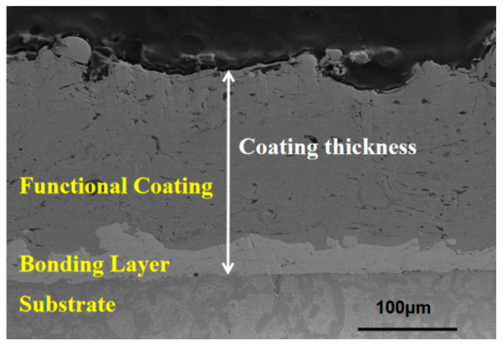
4.1. Thickness of the Coating
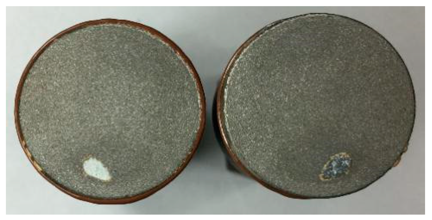
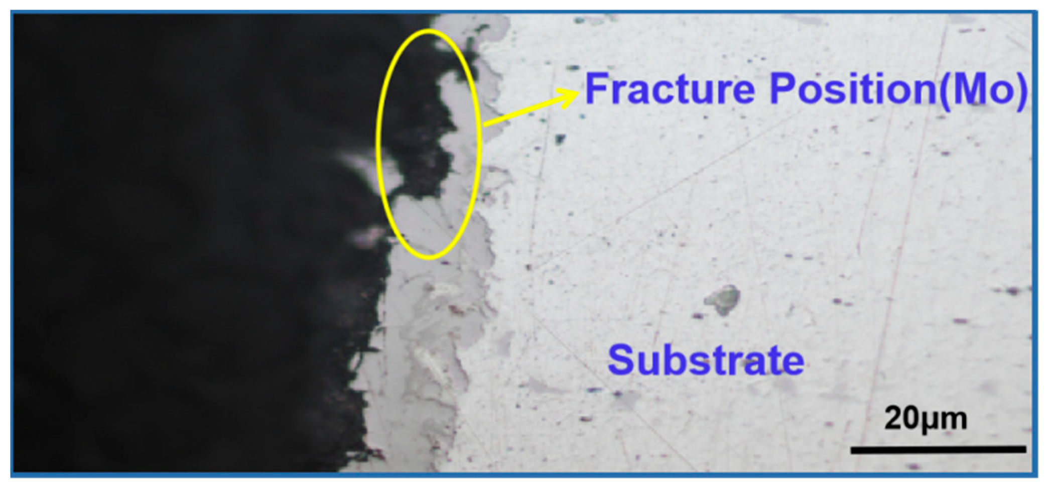
4.2. Bonding Strength of Coating
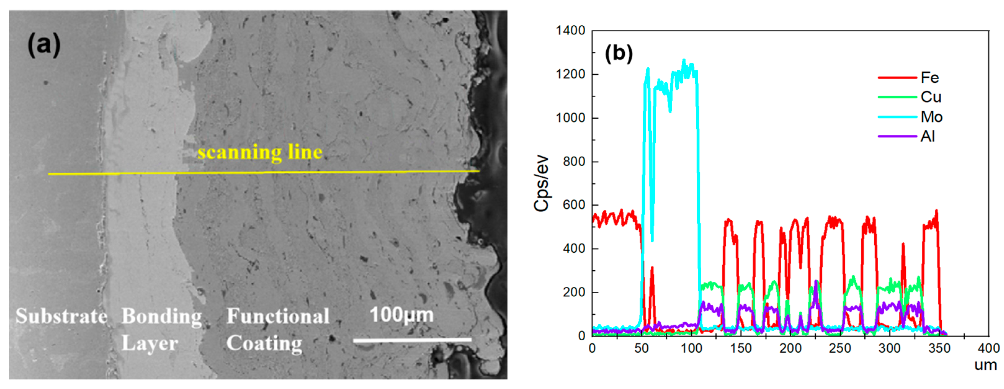
4.3. Analysis of the Cross-Sectional Morphology of the Coating
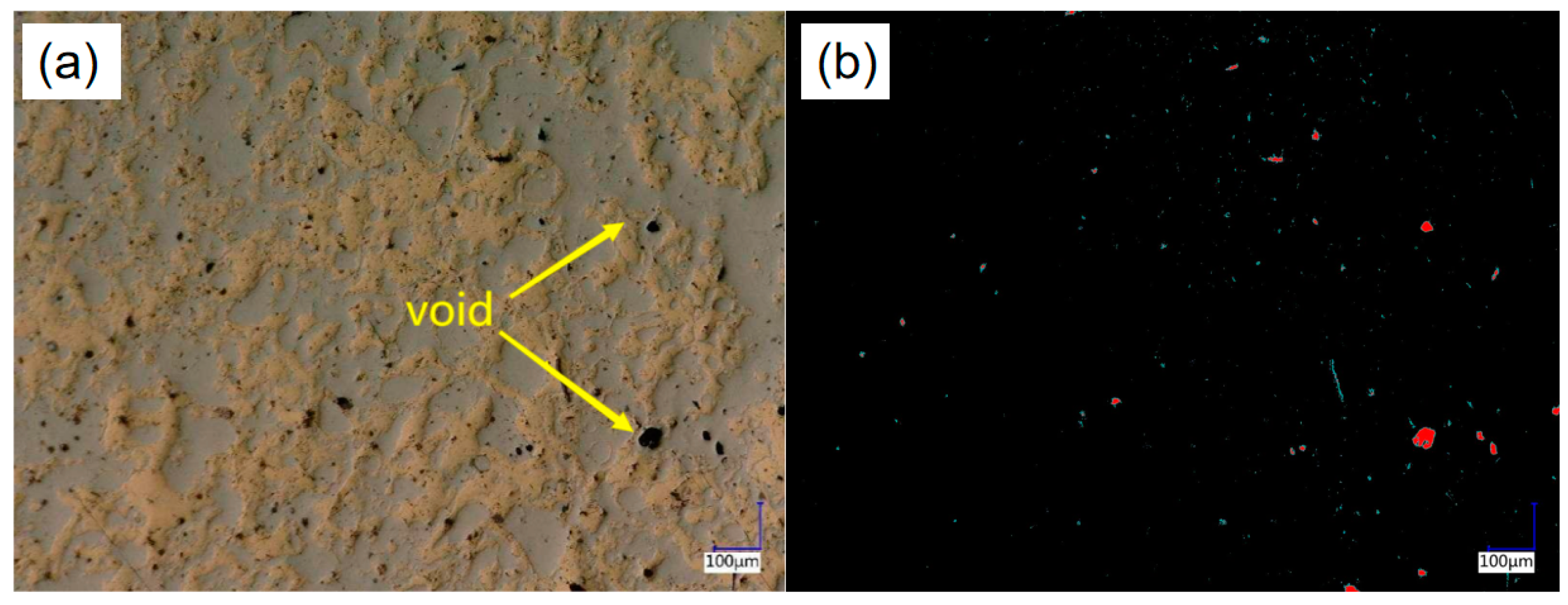
4.4. Analysis of Coating Surface Morphology
4.5. EBSD Analysis of the Composite Coating
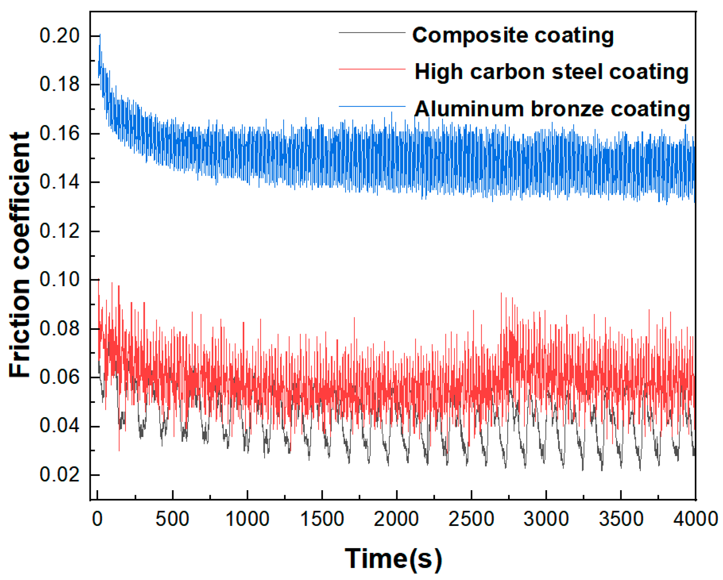
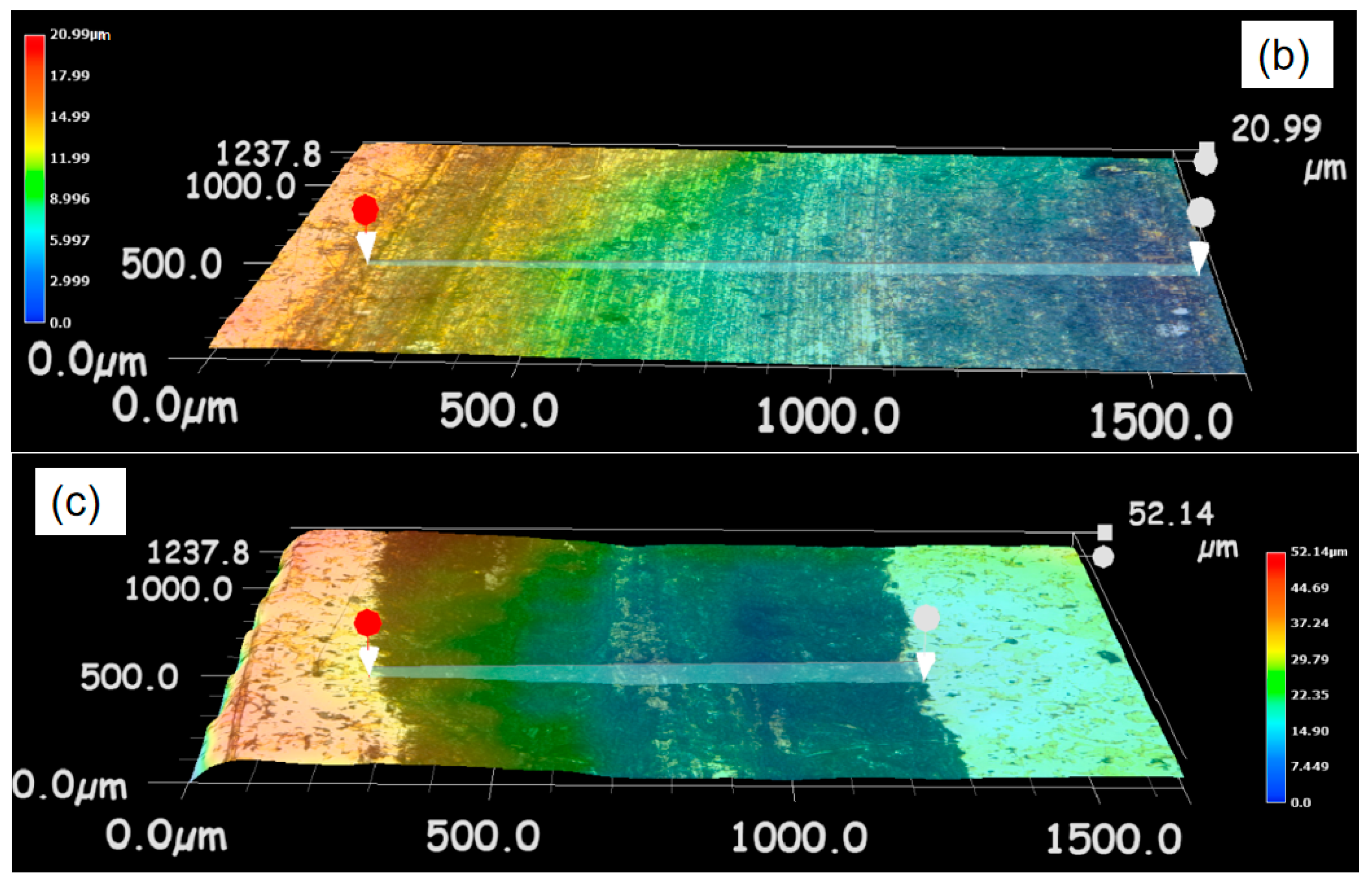
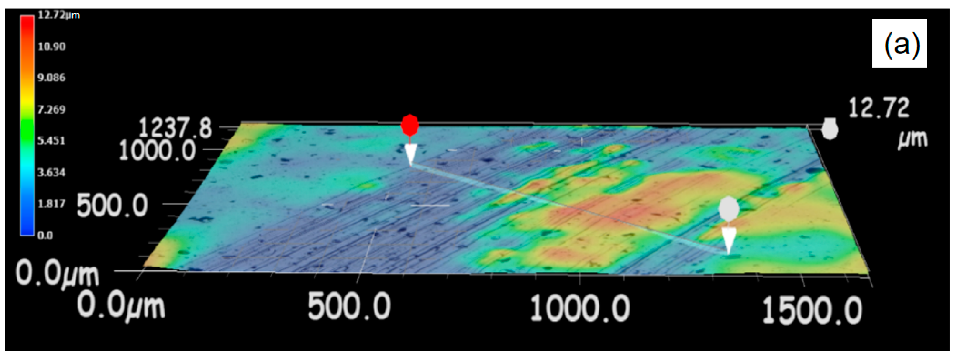
4.6. Wear Resistance Analysis
5. Conclusions
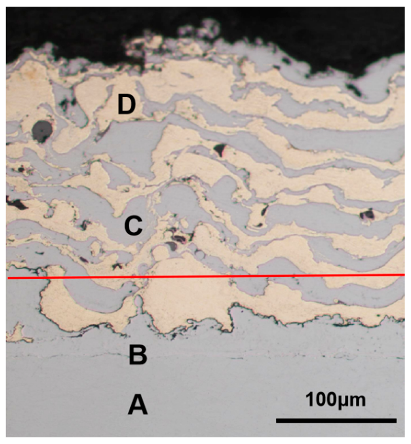
- It was feasible that the composite coating with a sponge-like spatial structure could be prepared by electro-explosive spraying technology. In the composite coating, high-carbon steel and aluminum bronze were closely combined and interwoven with each other in a staggered spatial structure, forming a sponge-like spatial structure.
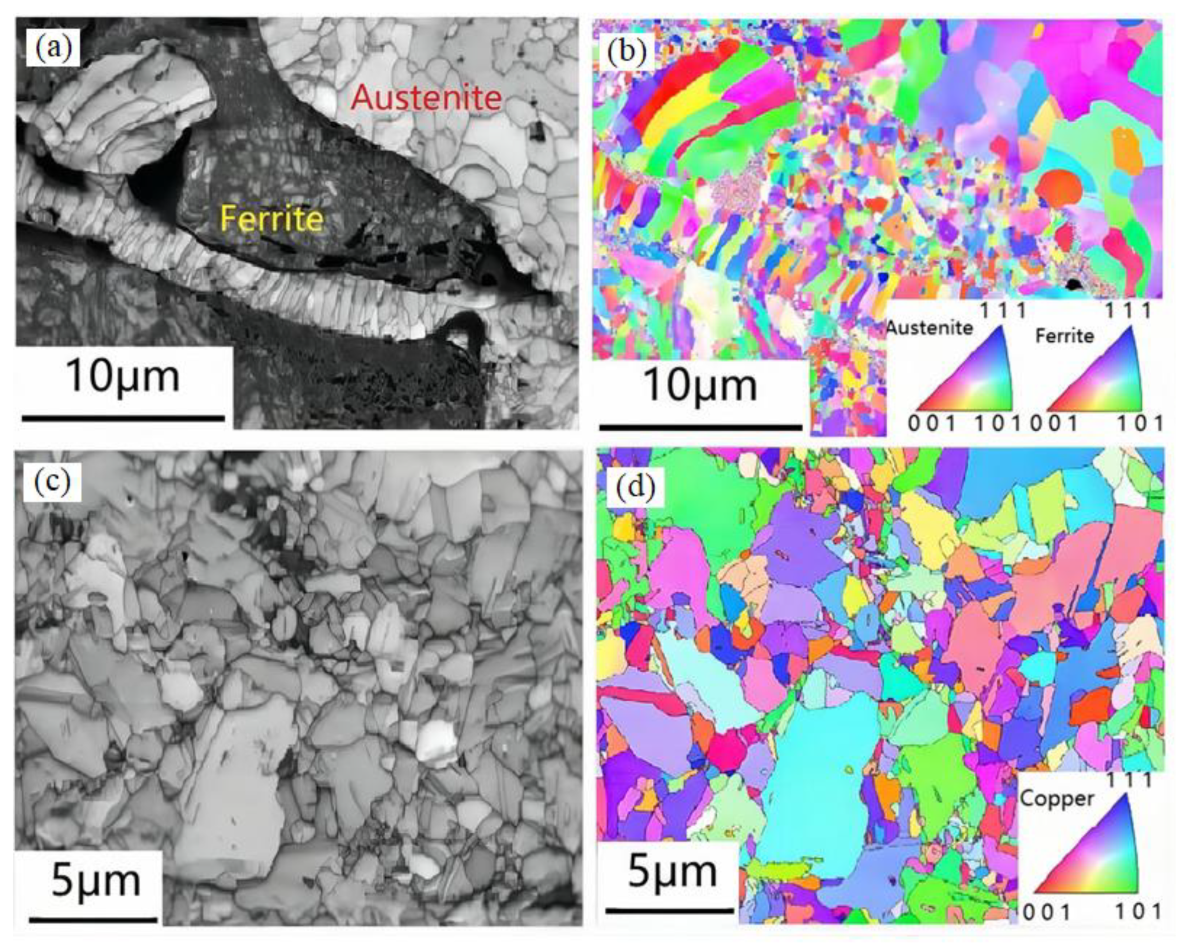
- The EBSD analysis of the coating showed that the strengthening mechanism of the composite coating prepared by electro-explosive spraying was a fine-grain strengthening mechanism and that the minimum grain size could reach a nanometer level.
- The composite coating had high bonding strength. The tensile experiment showed that the minimum and maximum bonding strength of the composite coating were 51.1 MPa and 56.2 MPa, respectively, and the failure occurred in the bonding area between the bonding layer and the functional coating, indicating that the bonding strength between the functional layers was greater than that between the bonding layer and the functional coating. The coating had good compactness and the porosity of the coating was 0.42%.
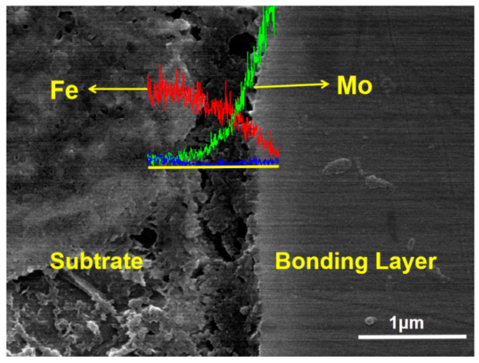
- SEM and EDS analysis showed that there was obvious atomic diffusion between the adjacent coating layers in the composite coating, indicating that there was metallurgical bonding as well as mechanical bonding between the adjacent coating layers. Metallurgical bonding was beneficial to improve the bonding strength of the composite coating.
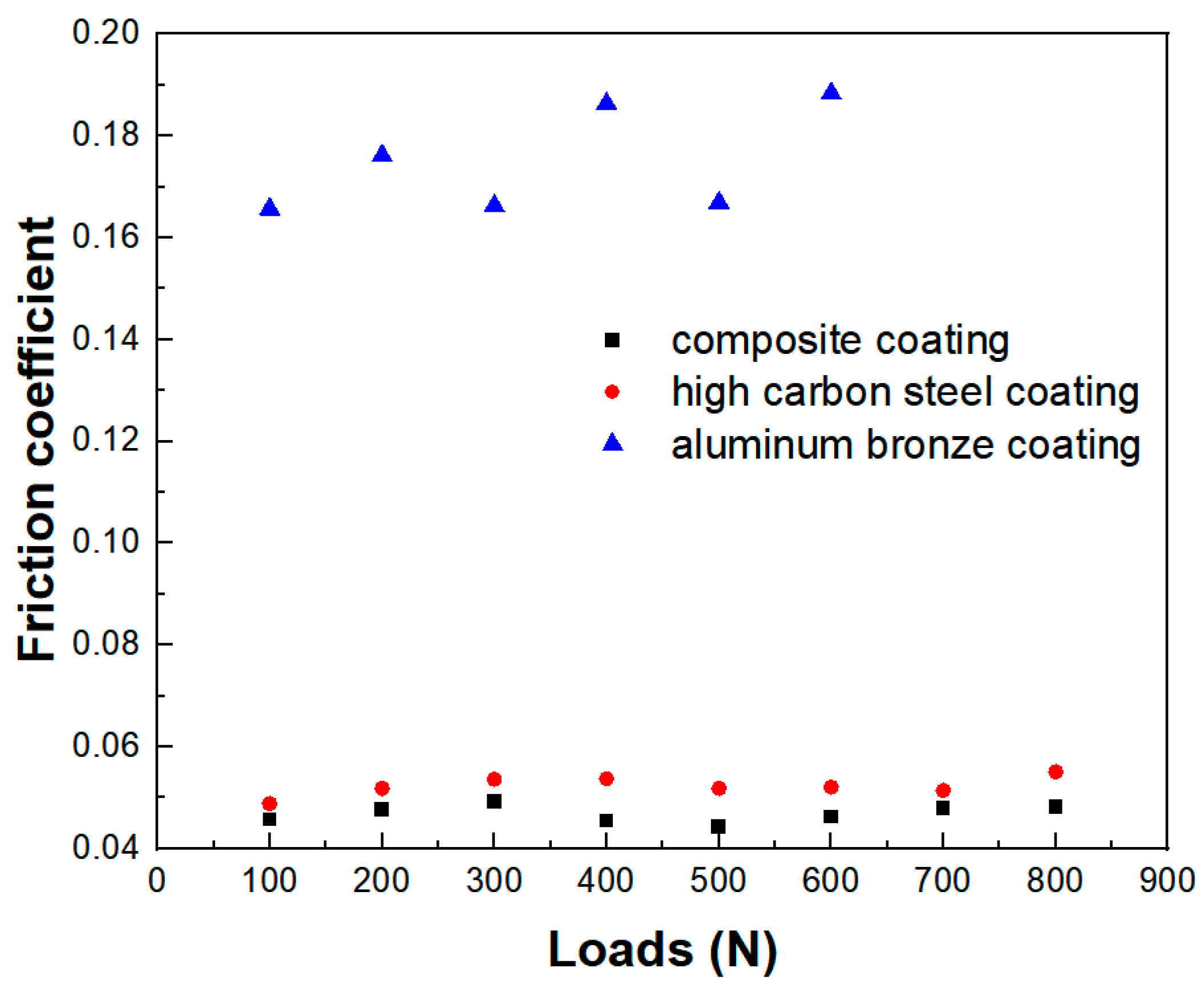
- The friction and wear experiments showed that the composite coating had a lower friction coefficient under a large load, which was 6–15% lower than that of the high-carbon steel coating, and only about 25% of that of the aluminum bronze coating, indicating that the composite coating had good wear resistance and that the aluminum bronze component in the composite coating played a role in lubricating and reducing wear.
Author Contributions
Funding
Institutional Review Board Statement
Informed Consent Statement
Data Availability Statement
Conflicts of Interest
References
- Liu, Y.H.; Qu, W.C.; Su, Y. TiC Reinforcement Composite Coating Produced Using Graphite of the Cast Iron by Laser Cladding. Materials 2016, 9, 815. [Google Scholar] [CrossRef] [PubMed] [Green Version]
- Ye, Y.W.; Wang, Y.X.; Chen, H.; Li, J.L.; Yao, Y.R.; Wang, C.Y. Doping carbon to improve the tribological performance of Cr N coatings in seawater. Tribol. Int. 2015, 90, 362–371. [Google Scholar] [CrossRef]
- Gilewicz, A.; Warcholinski, B. Tribological properties of CrCN/CrN multilayer coatings. Tribol. Int. 2014, 80, 34–40. [Google Scholar] [CrossRef]
- Daisuke, Y.; Junki, F.; Kohei, M. Fatigue and wear properties of Ti–6Al–4V alloy with Cr/CrN multilayer coating. Surf. Coat. Technol. 2015, 275, 232–238. [Google Scholar]
- Shtansky, D.V.; Bondarev, A.V.; Kiryukhantsev-Korneev, P.V.; Rojas, T.C.; Godinho, V.; Fernández, A. Structure and tribological properties of MoCN-Ag coatings in the temperature range of 25–700 °C. Appl. Surf. Sci. 2013, 273, 408–414. [Google Scholar] [CrossRef]
- Shan, L.; Wang, Y.X.; Li, J.L.; Chen, J.M. Effect of N2 flow rate on microstructure and mechanical properties of PVD CrNx coatings for tribological application in seawater. Surf. Coat. Technol. 2014, 242, 74–82. [Google Scholar] [CrossRef]
- Shan, L.; Wang, Y.X.; Li, J.L.; Jiang, X.; Chen, J.M. Improving tribological performance of CrN coatings in seawater by structure design. Tribol. Int. 2015, 82, 78–88. [Google Scholar] [CrossRef]
- Li, G.; Zhang, L.; Cai, F.; Yang, Y.; Wang, Q.M.; Zhang, S.H. Characterization and corrosion behaviors of Ti N/Ti Al N multilayer coatings by ion source enhanced hybrid arc ion plating. Surf. Coat. Technol. 2019, 366, 355–365. [Google Scholar] [CrossRef]
- Xian, G.; Xiong, J.; Zhao, H.B.; Fan, H.Y.; Li, Z.X.; Du, H. Evaluation of the structure and properties of the hard TiAlN-(TiAlN/CrAlSiN)-TiAlN multiple coatings deposited on different substrate materials. Int. J. Refract. Met. Hard Mater. 2019, 85, 105056. [Google Scholar] [CrossRef]
- Cai, F.; Zhang, J.M.; Wang, J.M.; Zheng, J.; Wang, Q.M.; Zhang, S.H. Improved adhesion and erosion wear performance of Cr Si N/Cr multi-layer coatings on Ti alloy by inserting ductile Cr layers. Tribol. Int. 2021, 153, 106657. [Google Scholar] [CrossRef]
- Nisha, V.; Vikram, J. Role of interface curvature on stress distribution under indentation for Zr N/Zr multilayer coating. Thin Solid Films 2014, 571, 283. [Google Scholar]
- Kong, J.Z.; Li, C.; Sun, X.Y.; Hai, Y.X.; Fa, Z.; Li, A.D.; Wang, Q.Z.; Zhou, F. Improved tribological properties and corrosion protection of CrN coating by ultrathin composite oxide interlayer. Appl. Surf. Sci. 2021, 541, 148606. [Google Scholar] [CrossRef]
- Jaime, O.P.; Mario, L.A.; Sarah, F.; Francesco, D.; Santiago, C.L. Role of Interface in Multilayered Composites under Irradiation: A Mathematical Investigation. Adv. Mater. Sci. Eng. 2017, 16, 1079735. [Google Scholar]
- Kameneva, A.; Kichigin, V. Corrosion wear and friction behavior of a number of multilayer two-, three- and multicomponent nitride coatings on different substrates, depending on the phase and elemental composition gradient. Adv. Mater. Sci. Eng. 2019, 489, 165–174. [Google Scholar] [CrossRef]
- Sivakumar, G.; Dusane, R.O.; Shrikant, V.J. A novel approach to process phase pure α-Al2O3 coatings by solution precursor plasma spraying. J. Eur. Ceram. Soc. 2013, 33, 2823–2829. [Google Scholar] [CrossRef]
- Vardelle, A.; Moreau, C.; Themelis, N.J.; Chazelas, C. A Perspective on Plasma Spray Technology. Plasma Chem. Plasma Process. 2015, 35, 491–509. [Google Scholar] [CrossRef]
- Tkachenko, S.I.; Barishpoltsev, D.V.; Ivanenkov, G.V.; Romanova, V.M.; Ter-Oganesyan, A.E.; Mingaleev, A.R.; Shelkovenko, T.A.; Pikuz, S.A. Analysis of the discharge channel structure upon nanosecond electrical explosion of wires. Phys. Plasmas 2007, 14, 123502. [Google Scholar] [CrossRef]
- Kotov, Y.A. Electric explosion of wires as a method for preparation of nanopowders. Nanoparticle Res. 2003, 5, 539–550. [Google Scholar] [CrossRef]
- Hou, S.X.; Liu, Z.D.; Liu, D.Y.; Li, B.R.; Zhang, N.Q. Microstructure and oxidation resistance of Mo–Si and Mo–Si–Al alloy coatings prepared by electro-thermal explosion ultrahigh speed spraying. Mater. Sci. Eng. A 2009, 518, 108–117. [Google Scholar] [CrossRef]
- Wang, J.; Peng, C.; Dai, H.; Lu, F.; Zhao, Z. Synthesis of Zirconium Dioxide Nanoparticles by Electrical Explosion of Zirconium Wire and Characteristics. Rare Metal Mater. Eng. 2019, 48, 2118–2121. [Google Scholar]
- Shi, H.T.; Hu, Y.J.; Li, T.; Tao, Z.P.; Li, X.W.; Wu, J. Anthony B Murphy and Aici Qiu. Detonation of a nitromethane-based energetic mixture driven by electrical wire explosion. J. Phys. D Appl. Phys. 2021, 55, 5. [Google Scholar]
- Shi, B.M.; Huang, S.M.; Zhu, P.; Xu, C.G.; Zhang, T.F. Microstructure and Wear Behaviorof In-Situ NbC Reinforced Composite Coatings. Materials 2020, 13, 3459. [Google Scholar] [CrossRef] [PubMed]
- Wang, X.D.; Wei, Y.P.; Zhou, H.; Liu, Q.H.; Zhu, L. Synthesis of graphene nanosheets by the electrical explosion of graphite powder confined in a tube. Ceram. Int. 2021, 47, 21934–21942. [Google Scholar] [CrossRef]
- Liu, J.J.; Liu, Z.D. An experimental study on synthesizing TiC–TiB2–Ni composite coating using electro-thermal explosion ultra-high speed spraying method. Mater. Lett. 2010, 64, 684–687. [Google Scholar] [CrossRef]
- Pan, J.Y.; Zheng, Y.T.; Zheng, Y.D.; Ye, W.; Yu, W.J. Solidification mechanism and microstructure evolution of Al2O3-ZrO2 ceramic coating prepared by combustion synthesis and thermal explosion Spraying. Ceram. Int. 2017, 43, 4037–4041. [Google Scholar] [CrossRef]
- Wang, Y.T.; Chen, Y.F.; Liu, Z.D.; Xue, Z.Y.; Yang, G. Surface modifications of Al-based amorphous composite coatings on 7075 Al plate prepared by high-speed electrothermal explosion. Procedia Eng. 2012, 27, 1042–1047. [Google Scholar] [CrossRef] [Green Version]
- Liu, Z.D.; Hou, S.X.; Liu, D.Y.; Zhao, L.P.; Li, B.; Liu, J.J. An experimental study on synthesizing submicron MoSi2-based coatings using electrothermal explosion ultra-high speed spraying method. Surf. Coat. Technol. 2008, 202, 2917–2921. [Google Scholar] [CrossRef]
- Jin, G.; Xu, B.S.; Wang, H.D.; Li, Q.F.; Wei, S.C. Tribological properties of molybdenum coatings sprayed by electro-thermal explosion directional spraying. Surf. Coat. Technol. 2007, 201, 6678–6680. [Google Scholar] [CrossRef]
- Hideki, T.; Takahiko, O.; Mutsuhisa, N.; Yasuhiro, T.; Akira, B.S. Spraying of the brittle ceramic zirconium diboride by a wire explosion technique. J. Appl. Phys. 1994, 75, 1789. [Google Scholar]
- Morimoto, T.; Mukaihara, T.; Kusumoto, Y.; Oda, M.; Takeshima, K.; Yatoh, H. Development of Fine-Grained High-Carbon Steel in High Reduction Low Temperature Rolling. Steel Res. Int. 2011, 82, 155–163. [Google Scholar] [CrossRef]
- Liu, Y.J.; LI, Y.M.; Tan, Y.H.; Huang, B.Y. Apparent Morphologies and Nature of Packet Martensite in High Carbon Steels. J. Iron Steel Res. Int. 2006, 13, 40–46. [Google Scholar] [CrossRef]
- Wada, N.; Akiyoshi, K.; Morita, K.; Hokamoto, K. Reaction synthesis of several titanium oxides through electrical wire explosion in air and in water. Ceram. Int. 2013, 39, 7927–7933. [Google Scholar] [CrossRef]
- Jung, T.K.; Joh, D.W.; Lee, H.S.; Lee, M.H. Fabrication of Ni, Pt, Pt/Ni Nano Powders using Wire Explosion Process and Characterization. Procedia Eng. 2011, 10, 728–733. [Google Scholar] [CrossRef] [Green Version]
- Bai, Y.; Wang, Z.H.; Li, X.B.; Huang, G.S.; Li, C.X.; Li, Y. Microstructure an Mechanical Properties of Zn-Ni-Al2O3 Composite Coatings. Materials 2018, 11, 853. [Google Scholar] [CrossRef] [PubMed] [Green Version]
- Zhang, S.L.; Sun, X.J.; Dong, H. Mechanism of Austenite Evolution during Deformation of Ultra-High Carbon Steel. J. Iron Steel Res. Int. 2008, 15, 42–46. [Google Scholar] [CrossRef]
- Yan, W.; Chen, W.Q.; Li, L. Quality Control of High Carbon Steel for Steel Wires. Materials 2019, 12, 846. [Google Scholar] [CrossRef] [Green Version]


| Position Number | 1 | 2 | 3 | 4 | 5 | Average Value/μm | Standard Deviation/μm |
|---|---|---|---|---|---|---|---|
| Thickness (min) | 185 | 196 | 205 | 198 | 189 | 194.6 | 7.0 |
| Thickness (max) | 230 | 240 | 245 | 235 | 232 | 236.4 | 5.5 |
| Sample Number | Bonding Strength/MPa | Remark |
|---|---|---|
| 1 | 51.1 | Sample II |
| 2 | 53.8 | Sample II |
| 3 | 56.2 | Sample II |
| 4 | 53.1 | Sample II |
| Item | Value |
|---|---|
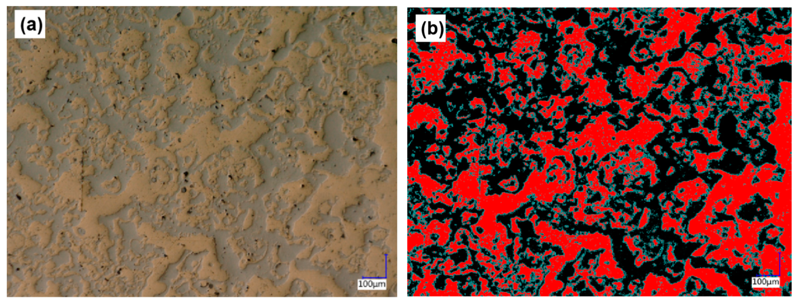
| Aluminum bronze area/μm2 | 1,129,502 |
| Counting point | 17,603 |
| Whole area of the region/μm2 | 2,146,703 |
| Area ratio of aluminum bronze/% | 53 |
| Item | Value |
|---|---|
| Pore area/μm2 | 9173 |
| Counting point | 1275 |
| Whole area of the region/μm2 | 2,146,703 |
| Porosity/% | 0.42 |
Publisher’s Note: MDPI stays neutral with regard to jurisdictional claims in published maps and institutional affiliations. |
© 2022 by the authors. Licensee MDPI, Basel, Switzerland. This article is an open access article distributed under the terms and conditions of the Creative Commons Attribution (CC BY) license (https://creativecommons.org/licenses/by/4.0/).
Share and Cite
Huang, K.; Song, Q.; Chen, P.; Liu, Y. Preparation and Performance of Mo/Cu/Fe Multi-Layer Composite Coating with Staggered Spatial Structure by Electro-Explosive Spraying Technology. Materials 2022, 15, 3552. https://doi.org/10.3390/ma15103552
Huang K, Song Q, Chen P, Liu Y. Preparation and Performance of Mo/Cu/Fe Multi-Layer Composite Coating with Staggered Spatial Structure by Electro-Explosive Spraying Technology. Materials. 2022; 15(10):3552. https://doi.org/10.3390/ma15103552
Chicago/Turabian StyleHuang, Kun, Qiuzhi Song, Pengwan Chen, and Ye Liu. 2022. "Preparation and Performance of Mo/Cu/Fe Multi-Layer Composite Coating with Staggered Spatial Structure by Electro-Explosive Spraying Technology" Materials 15, no. 10: 3552. https://doi.org/10.3390/ma15103552
APA StyleHuang, K., Song, Q., Chen, P., & Liu, Y. (2022). Preparation and Performance of Mo/Cu/Fe Multi-Layer Composite Coating with Staggered Spatial Structure by Electro-Explosive Spraying Technology. Materials, 15(10), 3552. https://doi.org/10.3390/ma15103552