
Effect of Nitrogen Ion Implantation on the Tool Life Used in Particleboard CNC Drilling

 ,
,  ,
,  ,
, 
 and
and
Abstract
1. Introduction
2. Materials and Methods
3. Results and Discussion
4. Conclusions
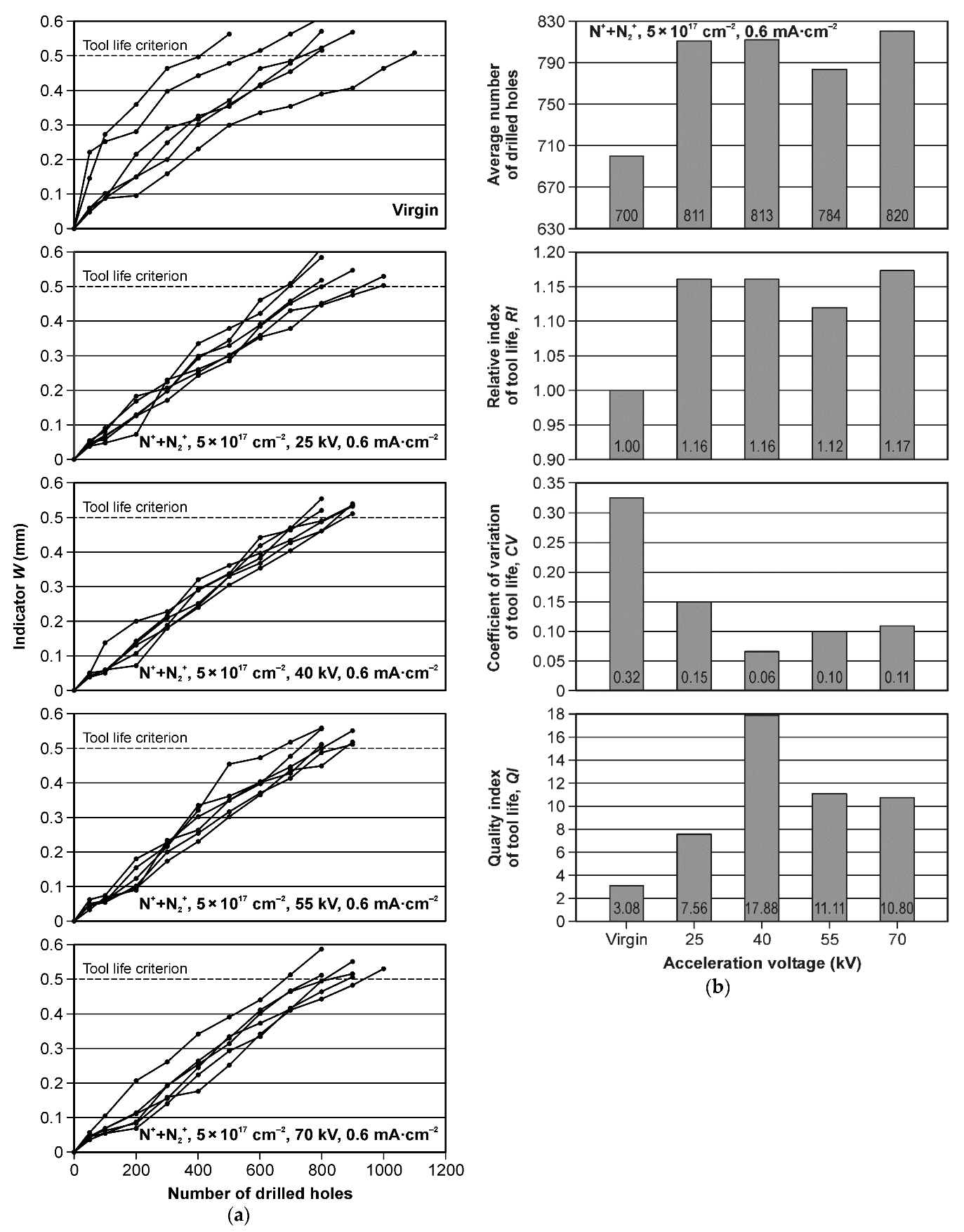
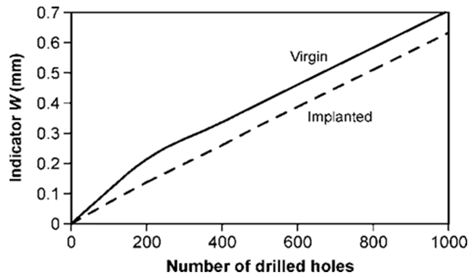
- The use of nitrogen ion implantation improved the wear resistance of the HSS drills and extended their tool life during CNC drilling of particleboard. The average tool life extension of the best implanted tool life variant was 17% as compared to that of the virgin tools.
- In the groups of implanted drills, the largest tool life was obtained for the modification variant with an acceleration voltage of 70 kV. The differences between the average results for the implanted groups were not statistically significant.
- Nitrogen ion implantation with an acceleration voltage of 40 kV is characterized by the highest quality of the modification process described by the quality index (QI). The index QI for this group of drills was 17.88, while for the virgin tools it was 3.08.
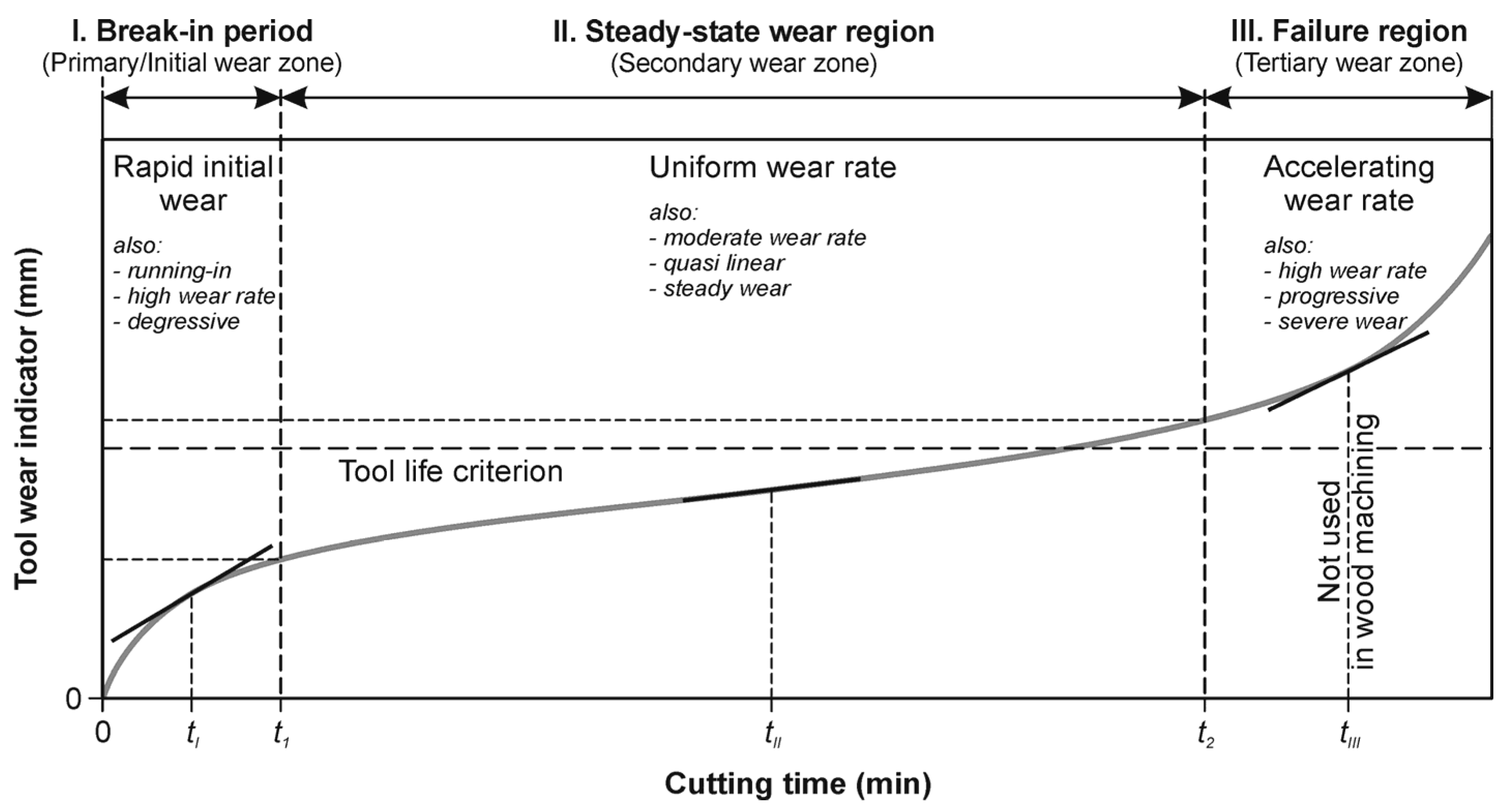
- The wear curves for the implanted tools do not follow the classic wear theory (the Lorenz wear curve). They are clearly linear, and no rapid initial wear in the break-in period occurs.
Author Contributions
Funding
Institutional Review Board Statement
Informed Consent Statement
Data Availability Statement
Acknowledgments
Conflicts of Interest
References
- Wilkowski, J.; Barlak, M.; Werner, Z.; Zagórski, J.; Czarniak, P.; Podziewski, P.; Szymanowski, K. Lifetime improvement and the cutting forces in nitrogen-implanted drills during wood-based material machining. Wood Fiber Sci. 2019, 51, 209–220. [Google Scholar] [CrossRef]
- Aknouche, H.; Outahyon, A.; Nouveau, C.; Marchal, R.; Zerizer, A.; Butaud, J. Tool wear effect on cutting forces: In routing process of Aleppo pine wood. J. Mater. Processing Technol. 2009, 209, 2918–2922. [Google Scholar] [CrossRef][Green Version]
- Benlatreche, Y.; Nouveau, C.; Marchal, R.; Ferreira Martins, J.P.; Aknouche, H. Applications of CrAlN ternary system in wood machining of medium density fibreboard (MDF). Wear 2009, 267, 1056–1061. [Google Scholar] [CrossRef]
- Wilkowski, J.; Barlak, M. The lifetime of cemented carbide blades during wood-based panels milling. Biul. Inf. OB-RPPD 2018, 3–4, 118–128. [Google Scholar] [CrossRef]
- Bradbury, S.R.; Lewis, D.B.; Sarwar, M. Assessment of enhancing the performance and wear characteristics of high speed steel circular saw blades through ion implantation. Surf. Coat. Technol. 1996, 82, 193–198. [Google Scholar] [CrossRef]
- Barlak, M.; Wilkowski, J.; Werner, Z. Modelling of nitrogen implantation processes into WC-Co indexable knives for wood-based material machining using ion implanters with or without direct ion beam. Ann. Wars. Univ. Life Sci. SGGW For. Wood Technol. 2019, 108, 68–78. [Google Scholar] [CrossRef]
- Barlak, M.; Wilkowski, J.; Szymanowski, K.; Czarniak, P.; Podziewski, P.; Werner, Z.; Zagórski, J.; Staszkiewicz, B. Influence of the ion implantation of nitrogen and selected metals on the lifetime of WC-Co indexable knives during MDF machining. Ann. Wars. Univ. Life Sci. SGGW For. Wood Technol. 2019, 108, 45–52. [Google Scholar] [CrossRef]
- Labidi, C.; Collet, R.; Nouveau, C.; Beer, P.; Nicosia, S.; Djouadi, M. Surface treatments of tools used in industrial wood machining. Surf. Coat. Technol. 2005, 200, 118–122. [Google Scholar] [CrossRef]
- Beer, P.; Rudnicki, J.; Bugliosi, S.; Sokołowska, A.; Wnukowski, E. Low temperature ion nitriding of the cutting knives made of HSS. Surf. Coat. Technol. 2005, 200, 146–148. [Google Scholar] [CrossRef]
- Warcholiński, B.; Gilewicz, A.; Szymański, W.; Pinkowski, G.; Olik, R. Improvment of durability of engineering tools for wood. Inżynieria Powierzchni 2011, 2, 73–80. [Google Scholar]
- Raebel, S.; Worzala, F.; Conrad, J. PSII nitrogen implanted M2 tool steel for wear resistance in wood machining tools. In Surface Engineering, 1st ed.; Shaker, S., Ed.; Elsevier Science Publishers Ltd.: London, UK, 1990; pp. 198–207. [Google Scholar] [CrossRef]
- Beer, P.; Rudnicki, J.; Ciupinski, L.; Djouadi, M.; Nouveau, C. Modification by composite coatings of knives made of low alloy steel for wood machining purposes. Surf. Coat. Technol. 2003, 174, 434–439. [Google Scholar] [CrossRef]
- Faga, M.; Settineri, L. Innovative anti-wear coatings on cutting tools for wood machining. Surf. Coat. Technol. 2006, 201, 3002–3007. [Google Scholar] [CrossRef]
- Djouadi, M.; Beer, P.; Marchal, R.; Sokolowska, A.; Lambertin, M.; Precht, W.; Nouveau, C. Antiabrasive coatings: Application for wood processing. Surf. Coat. Technol. 1999, 116, 508–516. [Google Scholar] [CrossRef]
- Taktak, S.; Ulker, S.; Gunes, I. High temperature wear and friction properties of duplex surface treated bearing steels. Surf. Coat. Technol. 2008, 202, 3367–3377. [Google Scholar] [CrossRef]
- Chekour, L.; Nouveau, C.; Chala, A.; Djouadi, M.A. Duplex treatment of 32CrMoV13 steel by ionic nitriding and triode sputtering: Application to wood machining. Wear 2003, 255, 1438–1443. [Google Scholar] [CrossRef]
- Barlak, M.; Piekoszewski, J.; Stanislawski, J.; Werner, Z.; Borkowska, K.; Chmielewski, M.; Sartowska, B.; Miskiewicz, M.; Starosta, W.; Walis, L.; et al. The effect of intense plasma pulse pre-treatment on wettability in ceramic-copper system. Fusion Eng. Des. 2007, 82, 2524–2530. [Google Scholar] [CrossRef]
- Narojczyk, J.; Werner, Z.; Barlak, M.; Morozow, D. The effect of Ti preimplantation on the properties of TiN coatings on HS 6-5-2 high-speed steel. Vacuum 2009, 83, 228–230. [Google Scholar] [CrossRef]
- Barlak, M.; Wilkowski, J.; Werner, Z. Ion implantation changes of tribological and corrosion resistance properties of materials used in wood industry. Ann. Wars. Univ. Life Sci. SGGW For. Wood Technol. 2016, 94, 19–27. [Google Scholar]
- Werner, Z.; Jagielski, J.; Piekoszewski, J.; Kubiak, L.; Gunzel, R. Improvement of the wear properties of cutting tools implanted with nitrogen ions. Nukleonika 1999, 44, 261–264. [Google Scholar]
- Uglov, V.; Kholmetskii, A.; Kuleshov, A.; Rusalsky, D.; Rumyanceva, I.; Wei, R.; Vajo, J. Phase transformation of high speed steel after sequential nitrogen and boron high current density ions implantation. Surf. Coat. Technol. 2002, 158, 349–355. [Google Scholar] [CrossRef]
- Chou, Y.; Liu, J. Ion implantation of superhard ceramik cutting tools. J. Mater. Eng. Perform. 2004, 13, 398–405. [Google Scholar] [CrossRef]
- Straede, C. Application of ion implantation in tooling industry. Nucl. Instrum. Methods Phys. Res. Sect. B Beam Interact. Mater. At. 1996, 113, 161–166. [Google Scholar] [CrossRef]
- Mikkelsen, N.; Pedersen, J.; Straede, C. Ion implantation–the job coater’s supplement to coating techniques. Surf. Coat. Technol. 2002, 158, 42–47. [Google Scholar] [CrossRef]
- Rodríguez, R.; Medrano, A.; Rico, M.; Sánchez, R.; Martínez, R.; García, J. Niche sectors for economically competitive ion implantation treatments. Surf. Coat. Technol. 2002, 158, 48–53. [Google Scholar] [CrossRef]
- Morozow, D.; Barlak, M.; Werner, Z.; Pisarek, M.; Konarski, P.; Zagórski, J.; Rucki, M.; Chałko, L.; Łagodziński, M.; Narojczyk, J.; et al. Wear resistance improvement of cemented tungsten carbide deep–hole drills after ion implantation. Materials 2021, 14, 239. [Google Scholar] [CrossRef]
- Barlak, M.; Chmielewski, M.; Werner, Z.; Pietrzak, K. Changes of tribological properties of Inconel 600 after ion implantation process. Bull. Pol. Acad. Sci. Tech. Sci. 2014, 62, 827–833. [Google Scholar] [CrossRef]
- Guzman, L.; Ciaghi, L.; Giacomozzi, F.; Voltolini, E.; Peacock, A.; Dearnaley, G.; Gardner, P. Ion implantation in WC-Co: Analysis of treated surfaces and testing of industrial tools. Mater. Sci. Eng. A 1989, 116, 183–191. [Google Scholar] [CrossRef]
- Sheikh-Ahmad, J.; Bailey, J. High-temperature wear of cemented tungsten carbide tools while machining particleboard and fiberboard. J. Wood Sci. 1999, 45, 445–455. [Google Scholar] [CrossRef]
- Piekoszewski, J.; Olesińska, W.; Jagielski, J.; Kaliński, D.; Chmielewski, M.; Werner, Z.; Barlak, M.; Szymczyk, W. Ion implanted nanolayers in AlN for direct bonding with copper. Solid State Phenom. 2004, 99, 231–234. [Google Scholar] [CrossRef]
- Olesińska, W.; Kaliński, D.; Chmielewski, M.; Diduszko, R.; Włosiński, W.K. Influence of titanium on the formation of a “barrier” layer during joining an AlN ceramic with copper by the CDB technique. J. Mater. Sci. Mater. Electron. 2006, 17, 781–788. [Google Scholar] [CrossRef]
- Wilkowski, J.; Barlak, M.; Böttger, R.; Werner, Z.; Konarski, P.; Pisarek, M.; Wachowicz, J.; Von Borany, J.; Auriga, A. Effect of nitrogen ion implantation on the life time of WC-Co tools used in particleboard milling. Wood Mater. Sci. Eng. 2021, 1–12. [Google Scholar] [CrossRef]
- Available online: http://www.srim.org/ (accessed on 17 February 2022).
- Available online: https://uknibc.co.uk/SUSPRE/ (accessed on 2 March 2022).
- EN 323; Wood-Based Panels—Determination of Density. European Committee for Standardization: Brussels, Belgium, 1999.
- EN 317; Particleboards and Fibreboards—Determination of Swelling in Thickness after Immersion in Water. European Committee for Standardization: Brussels, Belgium, 1999.
- EN 310; Wood-Based Panels—Determination of Modulus of Elasticity in Bending and of Bending Strength. European Committee for Standardization: Brussels, Belgium, 1994.
- EN 319; Particleboards and Fibreboards—Determination of Tensile Strength Perpendicular to the Plane of the Board. European Committee for Standardization: Brussels, Belgium, 1993.
- Beer, P.; Djouadi, M.; Marchal, R.; Sokolowska, A.; Lambertin, M.; Czyzniewski, A.; Precht, W. Antiabrasive coatings in a new application–wood rotary peeling process. Vacuum 1999, 53, 363–366. [Google Scholar] [CrossRef]
- Porankiewicz, B.; Iskra, P.; Sandak, J.; Tanaka, C.; Jóźwiak, K. High-speed steel tool wear during wood cutting in the presence of high-temperature corrosion and mineral contamination. Wood Sci. Technol. 2006, 40, 673–682. [Google Scholar] [CrossRef]
- Porankiewicz, B.; Sandak, J.; Tanaka, C. Factors influencing steel tool wear when milling wood. Wood Sci. Technol. 2005, 39, 225–234. [Google Scholar] [CrossRef]


| Acceleration Voltage (kV) | Percentage Charge State Distribution (%) | |
|---|---|---|
| N2+ | N+ | |
| 67 | 33 | |
| Energy (keV) | ||
| 25 | 12.5 | 25 |
| 40 | 20 | 40 |
| 55 | 27.5 | 55 |
| 70 | 35 | 70 |
| Material | Density (kg/m3) | Tensile Strength (MPa) | Swelling after 24 h (%) | Flexural Strength MOR (MPa) | Modulus of Elasticity MOE (MPa) |
|---|---|---|---|---|---|
| The three-layer Particleboard | 648 | 0.41 | 20.5 | 8.68 | 2212 |
| Cycle No. | 1 | 2 | 3 | 4 | 5 | 6 | 7 | 8 | 9 | 10 | 11 | 12 |
|---|---|---|---|---|---|---|---|---|---|---|---|---|
| Holes count | 50 | 50 | 100 | 100 | 100 | 100 | 100 | 100 | 100 | 100 | 100 | 100 |
| Total | 50 | 100 | 200 | 300 | 400 | 500 | 600 | 700 | 800 | 900 | 1000 | 1100 |
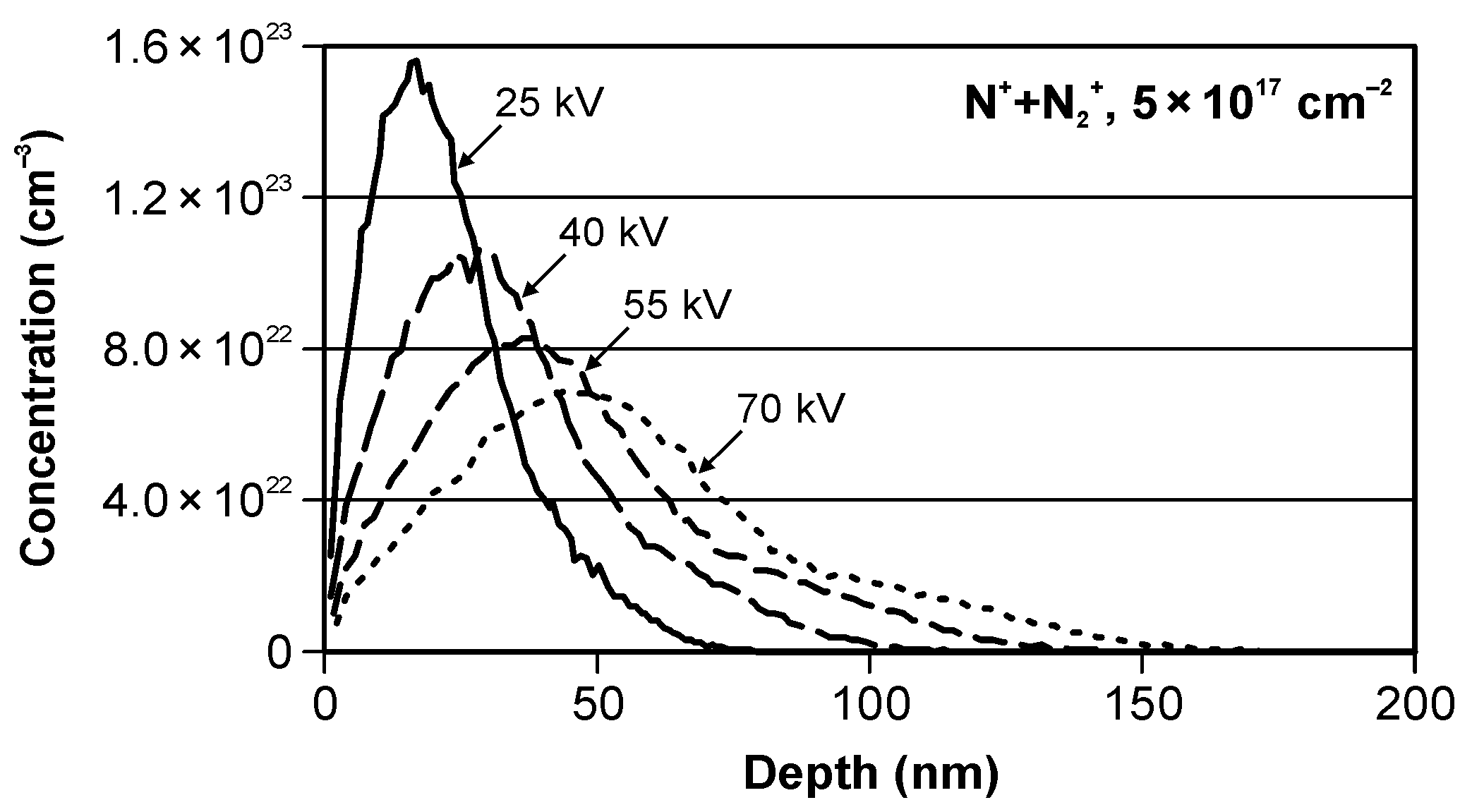
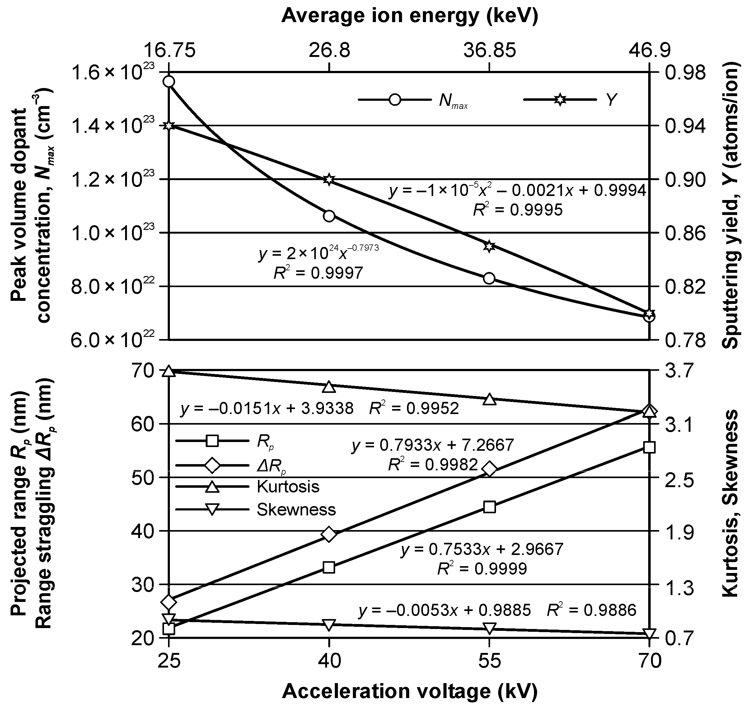
| Acceleration Voltage (kV) | Peak Volume Dopant Concentration Nmax (cm−3) | Projected Range Rp (nm) | Range Straggling ΔRp (nm) | Skewness | Kurtosis | Sputtering Yield Y (Atoms/Ion) |
|---|---|---|---|---|---|---|
| 25 | 1.56 × 10²³ | 21.7 | 26.6 | 0.8999 | 3.6942 | 0.94 |
| 40 | 1.06 × 10²³ | 33.2 | 39.4 | 0.8435 | 3.5118 | 0.9 |
| 55 | 8.3 × 10²² | 44.5 | 51.6 | 0.8055 | 3.3769 | 0.85 |
| 70 | 6.88 × 10²² | 55.6 | 62.2 | 0.7366 | 3.2345 | 0.8 |
Publisher’s Note: MDPI stays neutral with regard to jurisdictional claims in published maps and institutional affiliations. |
© 2022 by the authors. Licensee MDPI, Basel, Switzerland. This article is an open access article distributed under the terms and conditions of the Creative Commons Attribution (CC BY) license (https://creativecommons.org/licenses/by/4.0/).
Share and Cite
Wilkowski, J.; Jegorowa, A.; Barlak, M.; Werner, Z.; Zagórski, J.; Staszkiewicz, B.; Kurek, J.; Kruk, M. Effect of Nitrogen Ion Implantation on the Tool Life Used in Particleboard CNC Drilling. Materials 2022, 15, 3420. https://doi.org/10.3390/ma15103420
Wilkowski J, Jegorowa A, Barlak M, Werner Z, Zagórski J, Staszkiewicz B, Kurek J, Kruk M. Effect of Nitrogen Ion Implantation on the Tool Life Used in Particleboard CNC Drilling. Materials. 2022; 15(10):3420. https://doi.org/10.3390/ma15103420
Chicago/Turabian StyleWilkowski, Jacek, Albina Jegorowa, Marek Barlak, Zbigniew Werner, Jerzy Zagórski, Bogdan Staszkiewicz, Jarosław Kurek, and Michał Kruk. 2022. "Effect of Nitrogen Ion Implantation on the Tool Life Used in Particleboard CNC Drilling" Materials 15, no. 10: 3420. https://doi.org/10.3390/ma15103420
APA StyleWilkowski, J., Jegorowa, A., Barlak, M., Werner, Z., Zagórski, J., Staszkiewicz, B., Kurek, J., & Kruk, M. (2022). Effect of Nitrogen Ion Implantation on the Tool Life Used in Particleboard CNC Drilling. Materials, 15(10), 3420. https://doi.org/10.3390/ma15103420