
How Can We Provide Additively Manufactured Parts with a Fingerprint? A Review of Tagging Strategies in Additive Manufacturing

 ,
,  ,
,
Abstract
:
1. Introduction
2. Traceability and AM
2.1. Authentication or Identification?
2.2. Why Authenticate and Identify AM Parts?
2.3. Basic Requirements of Tagging Features in AM
- The tag should be tamper-resistant;
- The tag should be copy-resistant;
- The tag should be tear- and wear-resistant;
- The tag should be unobtrusive, meaning that it should fit the size and shape of the object;
- The tag should be compatible with the AM process in use, meaning that its implementation should easily integrate into the printing workflow. For sensors and detectors, which must be embedded into the part, the integration procedure should not interfere with the printing hardware and normal operations; for embedded structural features, ideally the tag should be printable with the part itself, otherwise its implementation should require minimal additional steps;
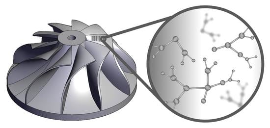
- The tag should be compatible with the part’s intended usage; for example, deterministic marks based on pores or local density alterations should not undermine the structural reliability of load-bearing components, whereas chemical fingerprints should not compromise the biocompatibility of biomedical devices;
- The tag should have a minimal impact on the part’s cost, as only few parts would have an added value high enough to justify the cost increase;
- If identification is required and not just authentication, the tag should be universally unique; otherwise, the tag should support namespacing. In computing, a namespace is a set of signs that are applied to identify and refer to objects of various kinds. As an example, in hierarchical file systems, files are grouped in directories, where each directory is a separate namespace. Even if the same name is attributed to two files in two different directories, the files remain uniquely identified because they belong to different namespaces;
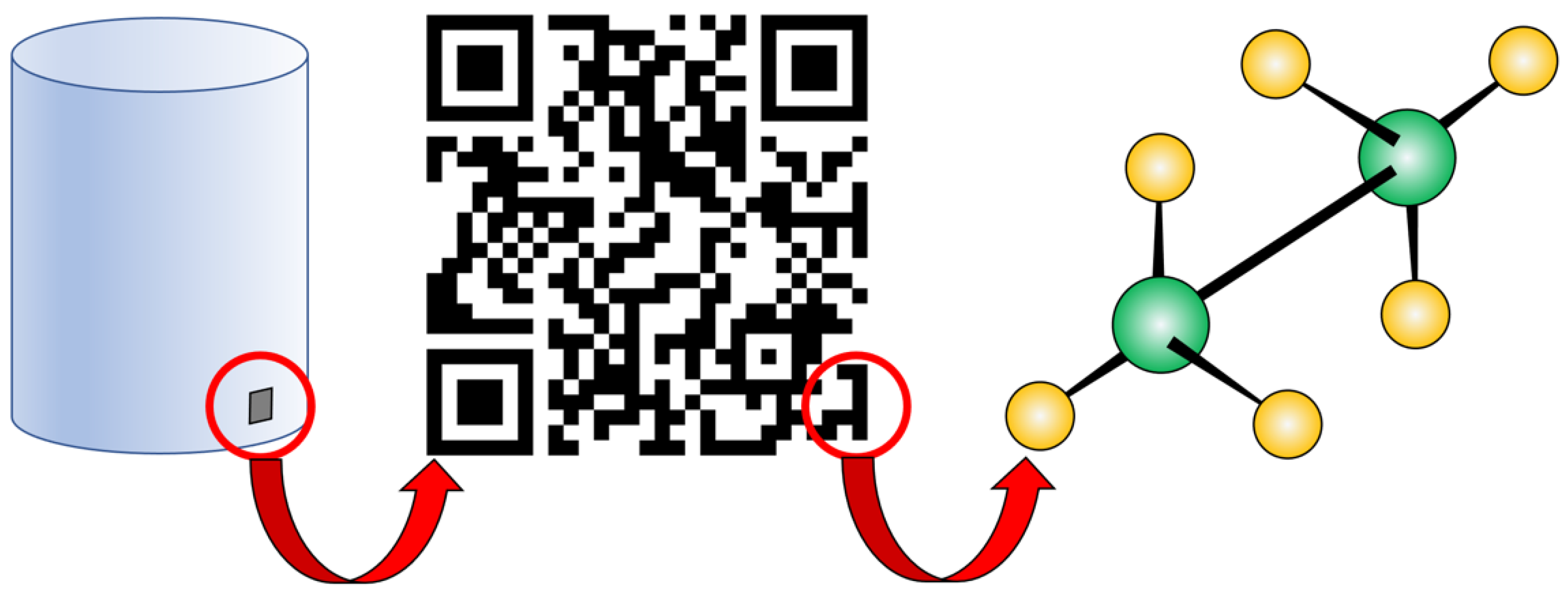
- The tag should be “detectable”, which means that its presence should be easily and unambiguously revealed with an appropriate detector. For instance, the presence of a unique combination of chemical elements embedded as a chemical fingerprint can be detected with an X-ray spectrophotometer. It is worth noting that, in this example, the tagging feature is a precise mix of specific elements in specific weight fractions and, therefore, as an integral part of the detection process, the detector should be able to measure the relative amounts of such elements. Basically, “detection” is responsible for conveying a minimum amount of information: “Yes” or “No”, namely, “yes, the tag is present” as opposed to “no, the tag is not present”. Interestingly, “detectability” does not imply “visibility”, as long as anti-counterfeiting marks can be detectable with an appropriate probing system but hidden from sight for an additional level of security. In principle, if the same tagging feature is common to all the products from the same producer, detection can suffice for authentication; if the tagging feature is unique to each product, detection can suffice for identification;
- Although, strictly speaking, this is not required for authentication and identification, tags may be “readable”. In particular, this is the case of deterministic tagging features that encode a precise message, for example, the QR code that contains the serial number of a product. In order to read a deterministic tag, the detector should be coupled with a program that converts the acquired data to structured “bits” of information. In this way, the “tag detector” becomes a “tag reader” and both the tag reader and the associated de-coding program must be trusted to correctly read and interpret the tagging feature. Interestingly, the operator that receives the product (which, in different scenarios, may be the end user, the customer, or an intermediate actor along the supply chain) has in mind an expected manufacturer and, accordingly, makes a guess of the appropriate verification method to detect and read the expected tag from that manufacturer.
2.4. How to Tag?
- Introduction of detectors: a mechatronic component (for example, a radio frequency identification (RFID) chip) that is integrated within the printed part or placed on its surface; whereas standard radio frequency (RF) tags have no identification capability, RFID tags transmit a signal that carries a code to identify it from a multitude of other tags;
- Introduction of embedded “structural” features: the AM process is used to provide the part with a tag that is integral to the structure of the part itself such as a geometric mark (for example, a barcode or a QR code), a chemical fingerprint or a random distribution of “spots” (for instance, pores, impurities or optical markers).
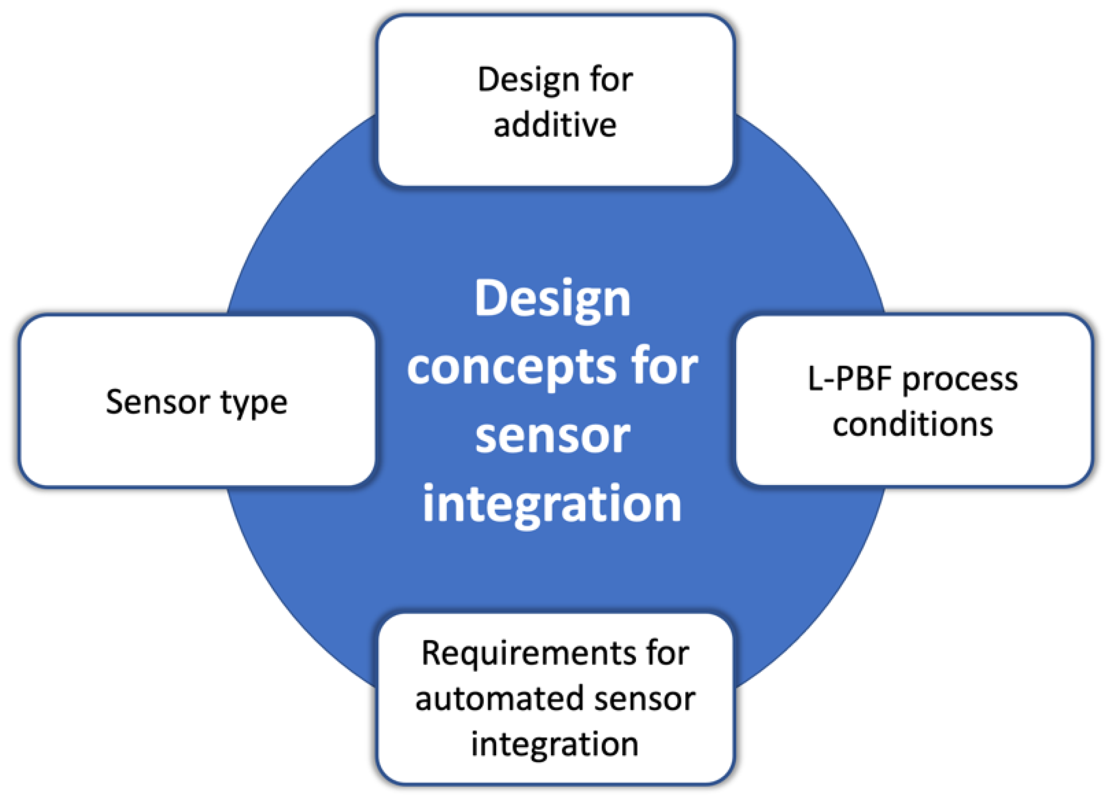
3. Sensors and Detectors
- To start printing the part, which has a geometry that includes a cavity to receive the sensor;
- To interrupt the job to open the cavity by powder removal and to place the tagging device inside the cavity;
- To complete the printing job.
4. Embedded “Structural” Features
4.1. Embedded Tagging Features in Metal-Based AM
- They should be metallurgically bonded well upon processing (=the two metals should have a low liquid-phase contact angle)
- They should be easily distinguished by some handy detection technique, such as infrared spectroscopy, X-ray fluorescence or X-ray imaging (=the two metals should have markedly different compositions, thermal properties or densities)
4.2. Embedded Tagging Features in Polymer-Based AM
4.2.1. Non-Deterministic Tagging Features
- The relationship between input-challenge and output-response is defined via a physical system; this means that the information about the part’s unicity can be inferred from the distribution of quantum dots only if a proper detection method is applied; in this case, a fluorescence microscope operated at the right magnification, since different patterns of fluorescence signals can be detected from the same object under different magnifications;
- The distribution of quantum dots is completely random;
- The distribution of quantum dots in unclonable, since it cannot be reproduced even by the original manufacturer.
4.2.2. Deterministic Tagging Features

| Reference | AM Technique | Tag | Reading Device |
|---|---|---|---|
| Chen et al., 2017 [21] 1 | FFF | Features in CAD file | Naked eye (inspection for defects) |
| Chen et al., 2019 [13] | FFF | QR code, ABS + support material | micro-CT scanner |
| Chen et al., 2019 [13] | PolyJet | QR code, resin + support material | micro-CT scanner |
| Chen et al., 2019 [13] | PolyJet | QR code, bi-material | micro-CT scanner |
| Chen et al., 2019 [22] | FFF | QR code, ABS + support material | micro-CT scanner |
| Chen et al., 2019 [22] | PolyJet | QR code, bi-material | Digital camera |
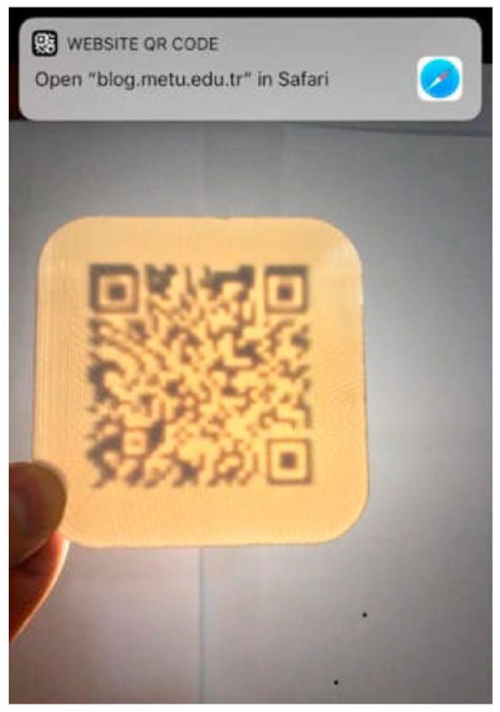
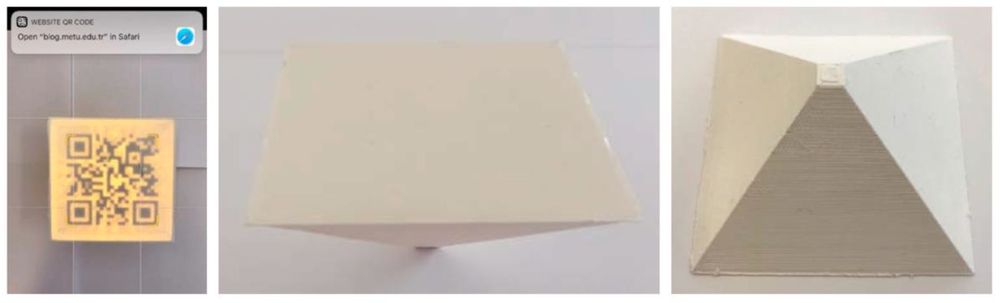
| Gültekin et al., 2019 [24] | FFF | Engraved QR code on internal surface | Phone camera; backlight |
| Ivanova et al., 2014 [25] | PolyJet | Quantum dots | Fluorescence microscope |
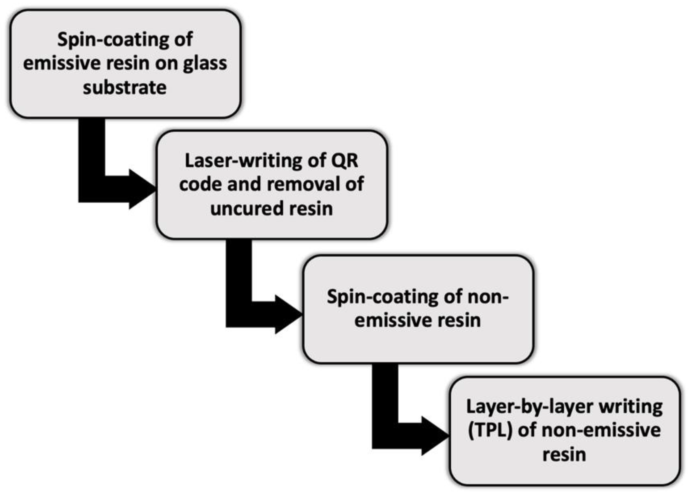
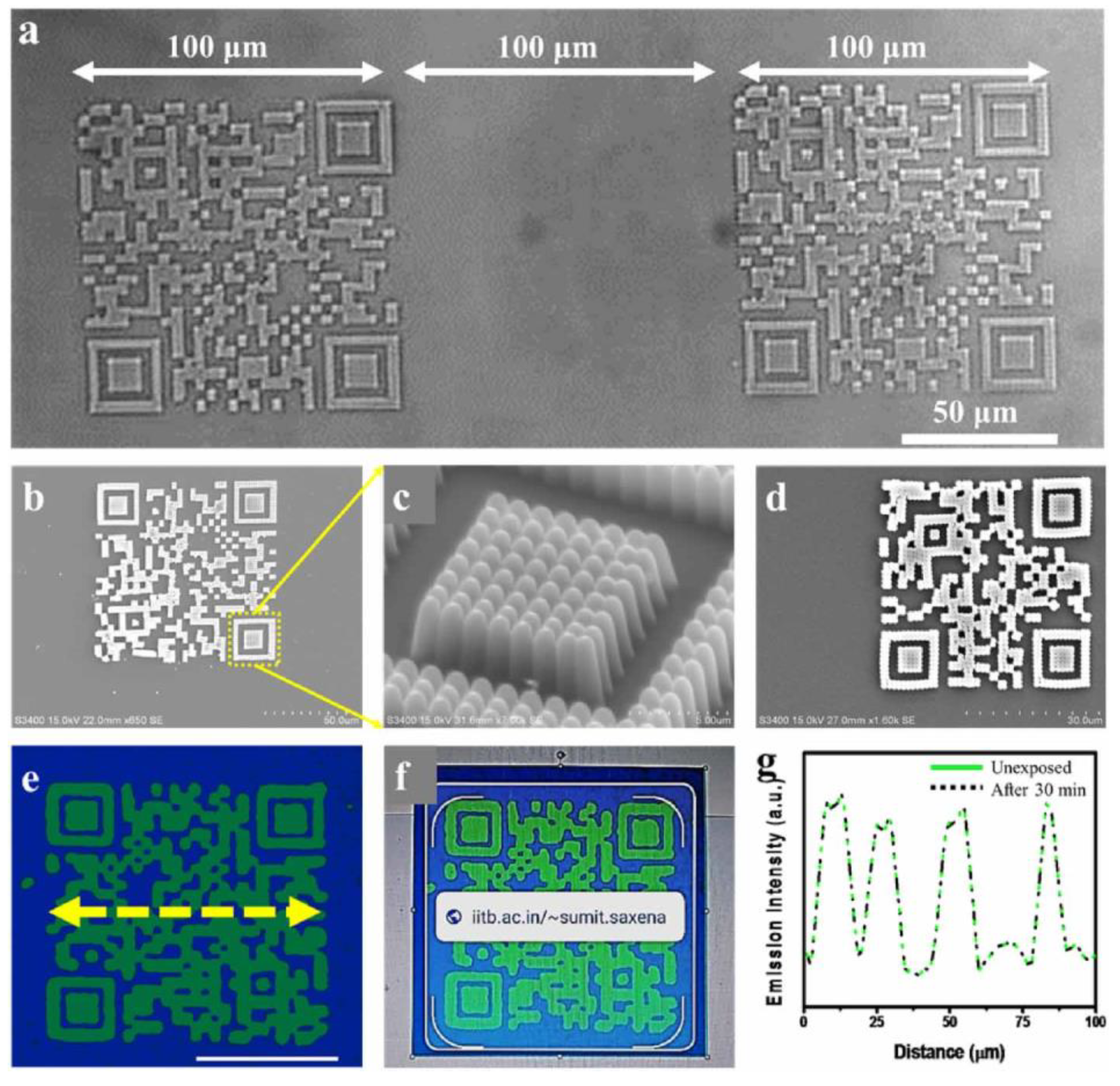
| Jaiswal et al., 2021 [26] | TPL | Carbon dots | Smartphone (Google Lens); UV lamp |
| Kennedy et al., 2017 [51] | FFF | Lanthanide–aspartic acid NPs | Handheld UV lamp (+Blockchain) |
| Kikuchi et al., 2018 [27] | FFF | Engraved QR code on freeform surface | Phone camera; ambient lightning |
| Kuang et al., 2019 [53] | g-LDP | Selective curing and dye diffusion | Naked eye; UV lamp |
| Li et al., 2017 [28] | PolyJet | Air pockets | Imaging by light projector and camera |
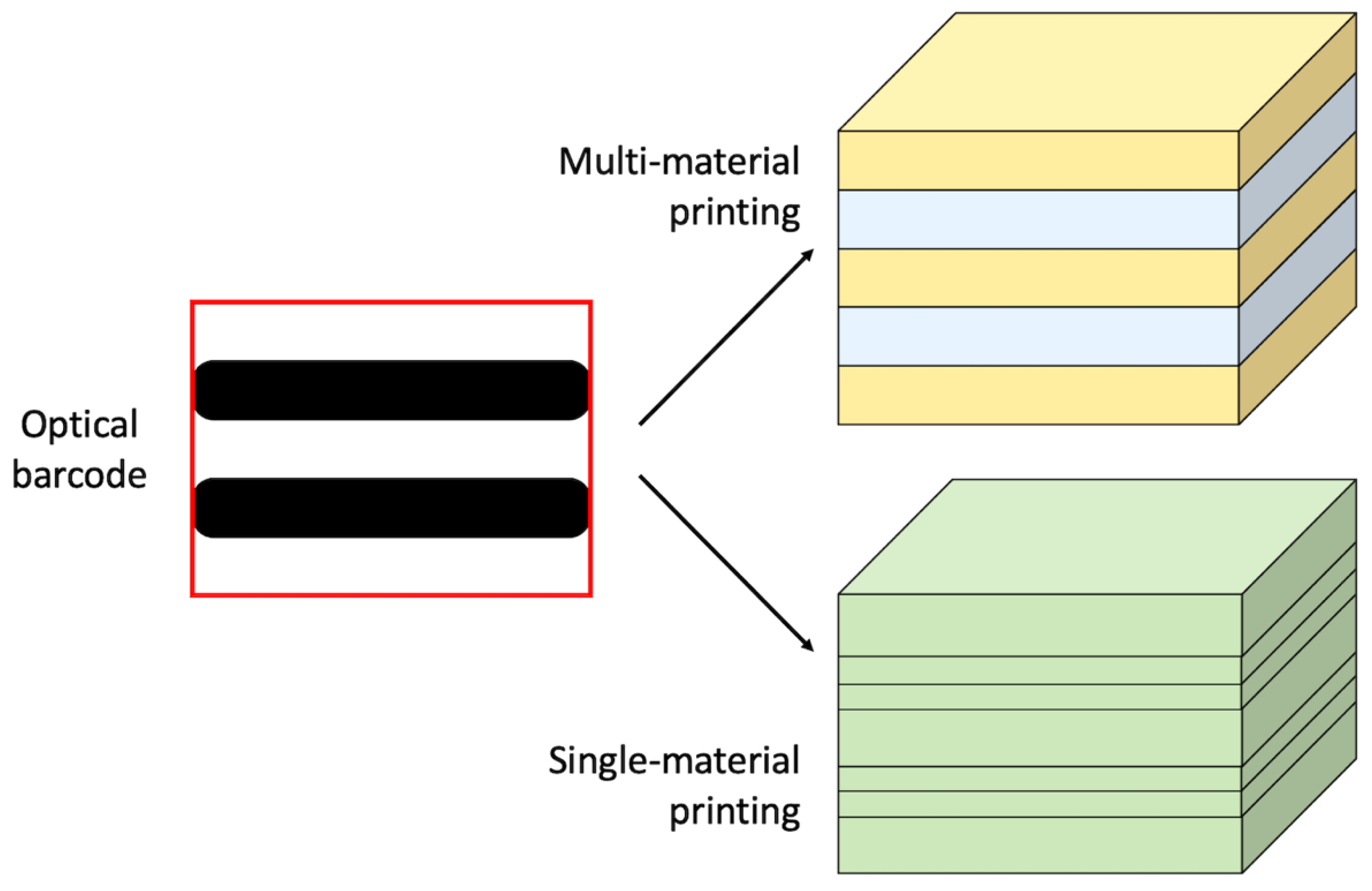
| Maia et al., 2019 [29] | PolyJet | Layers with different colours | Digital or iPhone cameras |
| Maia et al., 2019 [29] | FFF | Layers with variable deposition height | Digital or iPhone cameras |
| Maia et al., 2019 [29] | SLA | Layers with/without NIR dye | Camera with NIR filter |
5. Discussion and Critical Considerations
5.1. Feedstock-Related Specificities: Metal AM vs. Polymer AM
5.2. Microstructural Issues
5.3. Open Challenges and Growth Directions
6. Conclusions
Author Contributions
Funding
Institutional Review Board Statement
Informed Consent Statement
Data Availability Statement
Acknowledgments
Conflicts of Interest
References
- Godina, R.; Ribeiro, I.; Matos, F.; Ferreira, B.T.; Carvalho, H.; Peças, P. Impact Assessment of Additive Manufacturing on Sustainable Business Models in Industry 4.0 Context. Sustainability 2020, 12, 7066. [Google Scholar] [CrossRef]
- Reports and Data, Additive Manufacturing Market Analysis by Material Type (Metals, Thermoplastics, Ceramics, Others), by Metal Type (Titanium, Stainless Steel, High-Performance Alloys, Aluminum, Precious Metals, Others), by Polymer Type, by Ceramics Type, by Process, by End-Use, and Segment Forecasts to 2027. Available online: https://www.reportsanddata.com/report-detail/additive-manufacturing-market (accessed on 25 October 2021).
- Yeong, W.Y.; Chua, C.K. A quality management framework for implementing additive manufacturing of medical devices. Virtual Phys. Prototyp. 2013, 8, 193–199. [Google Scholar] [CrossRef]
- Matvieieva, N.; Neupetsch, C.; Oettel, M.; Makdani, V.; Drossel, W.-G. A novel approach for increasing the traceability of 3D printed medical products. Curr. Dir. Biomed. Eng. 2020, 6, 315–318. [Google Scholar] [CrossRef]
- Demestichas, K.; Peppes, N.; Alexakis, T.; Adamopoulou, E. Blockchain in agriculture traceability systems: A review. Appl. Sci. 2020, 10, 4113. [Google Scholar] [CrossRef]
- Yu, Z.; Jung, D.; Park, S.; Hu, Y.; Huang, K.; Rasco, B.A.; Wang, S.; Ronholm, J.; Lu, X.; Chen, J. Smart traceability for food safety. Crit. Rev. Food Sci. Nutr. 2020; in press. [Google Scholar] [CrossRef]
- Agrawal, T.K.; Kumar, V.; Pal, R.; Wang, L.; Chen, Y. Blockchain-based framework for supply chain traceability: A case example of textile and clothing industry. Comput. Ind. Eng. 2021, 154, 107130. [Google Scholar] [CrossRef]
- Cheng, M.J.; Simmons, J.E.L. Traceability in manufacturing systems. Int. J. Oper. Prod. Manag. 1994, 14, 4–16. [Google Scholar] [CrossRef]
- USP-NF. Supply Chain Integrity and Security–Briefing. Available online: https://www.uspnf.com/sites/default/files/usp_pdf/EN/USPNF/1083_4_scis_pf_40_4.pdf (accessed on 25 October 2021).
- Wei, C.; Sun, Z.; Huang, Y.; Li, L. Embedding anti-counterfeiting features in metallic components via multiple material additive manufacturing. Addit. Manuf. 2018, 24, 1–12. [Google Scholar] [CrossRef] [Green Version]
- Binder, M.; Kirchbichler, L.; Seidel, C.; Anstaett, C.; Schlick, G.; Reinhart, G. Design concepts for the integration of electronic components into metal laser-based powder bed fusion parts. Procedia CIRP 2019, 81, 992–997. [Google Scholar] [CrossRef]
- Eisenbarth, D.; Stoll, P.; Klahn, C.; Heinis, T.B.; Meboldt, M.; Wegener, K. Unique coding for authentication and anti-counterfeiting by controlled and random process variation in L-PBF and L-DED. Addit. Manuf. 2020, 35, 101298. [Google Scholar] [CrossRef]
- Chen, F.; Luo, Y.; Tsoutsos, N.G.; Maniatakos, M.; Shahin, K.; Gupta, N. Embedding tracking codes in additive manufactured parts for product authentication. Adv. Eng. Mater. 2019, 21, 1800495. [Google Scholar] [CrossRef]
- Flank, S.; Nassar, A.R.; Simpson, T.W.; Valentine, N.; Elburn, E. Fast authentication of metal additive manufacturing. 3D Print. Addit. Manuf. 2017, 4, 143–147. [Google Scholar] [CrossRef]
- Hastig, G.M.; Sodhi, M.S. Blockchain for Supply Chain Traceability: Business Requirements and Critical Success Factors. Prod. Oper. Manag. 2020, 29, 935–954. [Google Scholar] [CrossRef]
- Paz, J.F.I.; Wilbig, J.; Aumund-Kopp, C.; Petzoldt, F. RFID transponder integration in metal surgical instruments produced by additive manufacturing. Powder Metall. 2014, 57, 365–372. [Google Scholar] [CrossRef]
- Terranova, S.; Costa, F.; Manara, G.; Genovesi, S. Three-dimensional chipless RFID tags: Fabrication through additive manufacturing. Sensors 2020, 20, 4740. [Google Scholar] [CrossRef]
- Maldonado, N.; Amo-Ochoa, P. New promises and opportunities in 3D printable inks based on coordination compounds for the creation of objects with multiple applications. Chem. Eur. J. 2021, 27, 2887–2907. [Google Scholar] [CrossRef] [PubMed]
- 6th International Conference on Precision Machinery and Manufacturing Technology, Taiwan, 21–23 May 2021. In Journal of Physics: Conference Series 2020; IOP Science: Bristol, UK; Volume 2020, Issue 1, Code: 172124.
- Alkhader, W.; Alkaabi, N.; Salah, K.; Jayaraman, R.; Arshad, J.; Omar, M. Blockchain-based traceability and management for additive manufacturing. IEEE Access 2020, 8, 188363–188377. [Google Scholar] [CrossRef]
- Chen, F.; Mac, G.; Gupta, N. Security features embedded in computer aided design (CAD) solid models for additive manufacturing. Mater. Des. 2017, 128, 182–194. [Google Scholar] [CrossRef]
- Chen, F.; Yu, J.H.; Gupta, N. Obfuscation of embedded codes in additive manufactured components for product authentication. Adv. Eng. Mater. 2019, 21, 1900146. [Google Scholar] [CrossRef] [PubMed]
- Ghimire, T.; Joshi, A.; Sen, S.; Kapruan, C.; Chadha, U.; Selvaraj, S.K. Blockchain in additive manufacturing processes: Recent trends & its future possibilities. Mater. Today Proc. 2021; in press. [Google Scholar] [CrossRef]
- Gültekin, S.; Ural, A.; Yaman, U. Embedding QR codes on the interior surfaces of FFF fabricated parts. Procedia Manuf. 2019, 39, 519–525. [Google Scholar] [CrossRef]
- Ivanova, O.; Elliott, A.; Campbell, T.; Williams, C.B. Unclonable security features for additive manufacturing. Addit. Manuf. 2014, 1, 24–31. [Google Scholar] [CrossRef]
- Jaiswal, A.; Rani, S.; Singh, G.P.; Saxena, S.; Shukla, S. Two-photon lithography of fluorescence-encoded quick-read micro-code for anti-counterfeiting applications. J. Phys. Photonics 2021, 3, 034021. [Google Scholar] [CrossRef]
- Kikuchi, R.; Yoshikawa, S.; Jayaraman, P.K.; Zheng, J.; Maekawa, T. Embedding QR codes onto B-spline surfaces for 3D printing. Comput. Aided Des. 2018, 102, 215–223. [Google Scholar] [CrossRef]
- Li, D.; Nair, A.S.; Nayar, S.K.; Zheng, C. AirCode: Unobtrusive physical tags for digital fabrication. In: UIST ‘17. In Proceedings of the 30th Annual ACM Symposium on User Interface Software and Technology, Quebec City, QC, Canada, 22–25 October 2017; pp. 449–460. [Google Scholar] [CrossRef] [Green Version]
- Maia, H.T.; Li, D.; Yang, Y.; Zheng, C. LayerCode: Optical barcodes for 3D printed shapes. ACM Trans. Graph. 2019, 38, 1. [Google Scholar] [CrossRef]
- Shi, Z.; Kan, C.; Tian, W.; Liu, C. A Blockchain-based G-code protection approach for cyber-physical security in additive manufacturing. J. Comput. Inf. Sci. Eng. 2021, 21, 041007. [Google Scholar] [CrossRef]
- Yampolskiy, M.; King, W.E.; Gatlin, J.; Belikovetsky, S.; Brown, A.; Skjellum, A.; Elovici, Y. Security of additive manufacturing: Attack taxonomy and survey. Addit. Manuf. 2018, 21, 431–457. [Google Scholar] [CrossRef]
- Scott, C. Disney Files Patent Application for “Anti-Scanning” Material That Would Make Figurines Harder to Scan and 3D Print. Available online: https://3dprint.com/177483/disney-anti-scanning-patent (accessed on 25 October 2021).
- Voris, J.; Christen, B.F.; Alted, J.; Crawford, D.W. Three dimensional (3d) printed objects with embedded identification (id) elements. U.S. Patent No. 9,656,428 B2, 23 May 2017. [Google Scholar]
- Hou, J.; Kim, D.; Ahn, W.; Lee, H. Copyright protections of digital content in the age of 3D printer: Emerging issues and survey. IEEE Access 2018, 6, 44082–44093. [Google Scholar] [CrossRef]
- Jahnke, U.; Lindemann, C.; Moi, M.; Koch, R. Potentials of additive manufacturing to prevent product piracy. In Proceedings of the 24th Annual International Solid Freeform Fabrication Symposium: An Additive Manufacturing Conference, Austin, TX, USA, 12–14 August 2013; pp. 1023–1033. [Google Scholar]
- Zīle, K.; Strazdiņa, R. Blockchain use cases and their feasibility. Appl. Comput. Syst. 2018, 23, 12–20. [Google Scholar] [CrossRef] [Green Version]
- Bourell, D.; Kruth, J.P.; Leu, M.; Levy, G.; Rosen, D.; Beese, A.M.; Clare, A. Materials for additive manufacturing. CIRP Ann. 2017, 66, 659–681. [Google Scholar] [CrossRef]
- Lehmhus, D.; Aumund-Kopp, C.; Petzoldt, F.; Godlinski, D.; Haberkorn, A.; Zöllmer, V.; Busse, M. Customized Smartness: A Survey on links between Additive Manufacturing and Sensor Integration. Procedia Technol. 2016, 26, 284–301. [Google Scholar] [CrossRef]
- Sehrt, J.T.; Witt, G. Additive manufacturing of smart parts and medical instruments. 17èmes Assises Européennes de Prototypage Rapide. In Proceedings of the 17th European Forum on Rapid Prototyping and Manufacturing, Paris, France, 12–14 June 2012; (abstract). Available online: https://afpr.asso.fr/content/assises/2012/resumes/s6_3.htm (accessed on 25 October 2021).
- Thompson, M.K.; Moroni, G.; Vaneker, T.; Fadel, G.; Campbell, R.I.; Gibson, I.; Bernard, A.; Schulz, J.; Graf, P.; Ahuja, B.; et al. Design for additive manufacturing: Trends, opportunities, considerations, and constraints. CIRP Ann. Manuf. Technol. 2016, 65, 737–760. [Google Scholar] [CrossRef] [Green Version]
- Sankara Narayanan, A. QR codes and security solutions. Int. J. Comput. Sci. Telecommun. 2012, 3, 69–72. [Google Scholar]
- UNICEF, 2019. Faces, Fingerprints & Feet. Guidance on Assessing the Value of Including Biometric Technologies in UNICEF-Supported Programs. UNICEF, July 2019. Available online: https://data.unicef.org/wp-content/uploads/2019/10/Biometrics_guidance_document_faces_fingersprint_feet-July-2019.pdf (accessed on 1 September 2021).
- GE Additive. Get the Facts on Porosity in Metal Additive Manufacturing. Available online: https://www.ge.com/additive/blog/get-facts-porosity-metal-additive-manufacturing (accessed on 1 September 2021).
- Sola, A.; Nouri, A. Microstructural porosity in additive manufacturing: The formation and detection of pores in metal parts fabricated by powder bed fusion. J. Adv. Manuf. Process. 2019, 1, e10021. [Google Scholar] [CrossRef]
- Scott, C. InfraTrac Successfully Applies Anti-Counterfeit Technology to 3D Printed Metal Parts. Available online: https://3dprint.com/157763/infratrac-3d-printed-metal-parts (accessed on 25 October 2021).
- Yang, K.V.; Rometsch, P.; Jarvis, T.; Rao, J.; Cao, S.; Davies, C.; Wu, X. Porosity formation mechanisms and fatigue response in Al-Si-Mg alloys made by selective laser melting. Mater. Sci. Eng. A 2018, 712, 166–174. [Google Scholar] [CrossRef]
- Elliott, A.M.; Ivanova, O.S.; Williams, C.B.; Campbell, T.A. Inkjet printing of quantum dots in photopolymer for use in additive manufacturing of nanocomposites. Adv. Eng. Mater. 2013, 15, 10. [Google Scholar] [CrossRef]
- Wickramasinghe, S.; Do, T.; Tran, P. FDM-Based 3D printing of polymer and associated composite: A review on mechanical properties, defects and treatments. Polymers 2020, 12, 1529. [Google Scholar] [CrossRef]
- Kok, Y.; Tan, X.P.; Wang, P.; Nai, M.L.S.; Loh, N.H.; Liu, E.; Tor, S.B. Anisotropy and heterogeneity of microstructure and mechanical properties in metal additive manufacturing: A critical review. Mater. Des. 2017, 139, 565–586. [Google Scholar] [CrossRef]
- Zhang, P.; Liu, J.; To, A.C. Role of anisotropic properties on topology optimization of additive manufactured load bearing structures. Scr. Mater. 2017, 135, 148–152. [Google Scholar] [CrossRef]
- Kennedy, Z.C.; Stephenson, D.E.; Christ, J.F.; Pope, T.R.; Arey, B.W.; Barrett, C.A.; Warner, M.G. Enhanced anti-counterfeiting measures for additive manufacturing: Coupling lanthanide nanomaterial chemical signatures with blockchain technology. J. Mater. Chem. C 2017, 5, 9570–9578. [Google Scholar] [CrossRef]
- Zhang, J.; Ge, M. A study of an anti-counterfeiting fiber with spectral fingerprint characteristics. J. Text. Inst. 2011, 102, 767–773. [Google Scholar] [CrossRef]
- Kuang, X.; Wu, J.; Chen, K.; Zhao, Z.; Ding, Z.; Hu, F.; Fang, D.; Qi, H.J. Grayscale digital light processing 3D printing for highly functionally graded materials. Sci. Adv. 2019, 5, eaav5790. [Google Scholar] [CrossRef] [Green Version]
- Wikipedia. Machine Identification Code. Available online: https://en.wikipedia.org/wiki/Machine_Identification_Code (accessed on 25 October 2021).
- EFF, Electronic Frontier Foundation. DocuColor Tracking Dot Decoding Guide. Available online: https://web.archive.org/web/20180305181029/; https://w2.eff.org/Privacy/printers/docucolor (accessed on 25 October 2021).
- Wohlers, T.; Gornet, T. History of Additive Manufacturing In Wohlers Report 2014—3D Printing and Additive Manufacturing State of the Industry; Cambridge University Press: Cambridge, UK, 2014; pp. 1–34. [Google Scholar]
- Sculpteo. The State of 3D Printing Report: 2020. Available online: https://www.sculpteo.com/en/ebooks/state-of-3d-printing-report-2020 (accessed on 25 October 2021).
- AMFG. 40+ 3D Printing Industry Stats You Should Know. Available online: https://amfg.ai/2020/01/14/40-3d-printing-industry-stats-you-should-know-2020-redirect (accessed on 25 October 2021).
- Karamessini, D.; Petit, B.E.; Bouquey, M.; Charles, L.; Lutz, J.-F. Identification-Tagging of Methacrylate-Based Intraocular Implants Using Sequence Defined Polyurethane Barcodes. Adv. Funct. Mater. 2017, 27, 1604595. [Google Scholar] [CrossRef] [Green Version]
- Wang, Z.; Yuan, H.; Zhang, Y.; Wang, D.; Ju, J.; Tan, Y. Recent progress in organic color-tunable phosphorescent materials. J. Mater. Sci. Technol. 2022, 101, 264–284. [Google Scholar] [CrossRef]
- Clough, J.M.; Weder, C.; Schrettl, S. Mechanochromism in Structurally Colored Polymeric Materials. Macromol. Rapid Commun. 2021, 42, 2000528. [Google Scholar] [CrossRef]
- Guo, Q.; Zhang, X. A review of mechanochromic polymers and composites: From material design strategy to advanced electronics application. Compos. B Eng. 2021, 227, 109434. [Google Scholar] [CrossRef]
- Zhang, Z.; Chen, Z.; Shang, L.; Zhao, Y. Structural Color Materials from Natural Polymers. Adv. Mater. Technol. 2021, 6, 2100296. [Google Scholar] [CrossRef]
- Krüger, K.; Kain, M.; Zhang, Y.; Pedersen, D.B.; Calaon, M.; Tosello, G.; Hansen, H.N. Enabling Micro Injection Moulding Using a Soft Tooling Process Chain with Inserts Made of Mortar Material. Micromachines 2021, 12, 857. [Google Scholar] [CrossRef]
- Dehoff, R.R.; Kirka, M.M.; Sames, W.J.; Bilheux, H.; Tremsin, A.S.; Lowe, L.E.; Babu, S.S. Site specific control of crystallographic grain orientation through electron beam additive manufacturing. Mater. Sci. Technol. 2015, 31, 931–938. [Google Scholar] [CrossRef]
- Chen, Z.; Li, Z.; Li, J.; Liu, C.; Lao, C.; Fu, Y.; Liu, C.; Li, Y.; Wang, P.; He, Y. 3D printing of ceramics: A review. J. Eur. Ceram. Soc. 2019, 39, 661–687. [Google Scholar] [CrossRef]
- Choi, T.-M. Blockchain-technology-supported platforms for diamond authentication and certification in luxury supply chains. Transp. Res. Part E Logist. Transp. Rev. 2019, 128, 17–29. [Google Scholar] [CrossRef]
- Westerkamp, M.; Victor, F.; Küpper, A. Tracing manufacturing processes using blockchain-based token compositions. Digit. Commun. Netw. 2020, 6, 167–176. [Google Scholar] [CrossRef]
- Guo, D.; Ling, S.; Li, H.; Ao, D.; Zhang, T.; Rong, Y.; Huang, G.Q. A framework for personalized production based on digital twin, blockchain and additive manufacturing in the context of Industry 4.0. In Proceedings of the 2020 IEEE 16th International Conference on Automation Science and Engineering (CASE), Online, 20–21 August 2020; pp. 1181–1186. [Google Scholar] [CrossRef]

| Reference | Keywords |
|---|---|
| Alkhader et al., 2020 [20] | Additive manufacturing, blockchain, supply chain, 3D printing, cybersecurity, trust, traceability |
| Binder et al., 2019 [11] | Additive manufacturing, laser-based powder bed fusion, sensor integration, design concepts, embedded electronics |
| Chen et al., 2017 [21] | Computer-aided design, additive manufacturing, 3D printing, security, cybersecurity |
| Chen et al., 2019 [13] | Additive manufacturing, computer-aided design, product authentication, security, 3D printing |
| Chen et al., 2019 [22] | 3D printing, additive manufacturing, anti-counterfeiting, reverse engineering, security |
| Eisenbarth et al., 2020 [12] | Powder bed fusion, directed energy deposition, coding, anti-counterfeiting, eddy current testing |
| Flanck et al., 2017 [14] | Metals additive manufacturing, anticounterfeiting, intellectual property protection |
| Ghimire et al., in press [23] | Industry 4.0, IoT, additive manufacturing, blockchain |
| Gültekin et al., 2019 [24] | QR code, additive manufacturing, 3D printing, fused filament fabrication |
| Ivanova et al., 2014 [25] | Additive manufacturing, nanocomposites, quantum dots, cryptograph |
| Jaiswal et al., 2021 [26] | Additive manufacturing, anti-counterfeiting, two-photon lithography, fluorescence encoding, sub-micron-scale patterned QR code |
| Kikuchi et al., 2018 [27] | QR code, B-spline surface, 3D printing |
| Li et al., 2017 [28] | Digital fabrication, 3D printing, unobtrusive tags, air pockets, sensing |
| Maia et al., 2019 [29] | 3D printing, information embedding, fabrication, physical hyperlinks |
| Matvieieva et al., 2020 [4] | MDR, component identification, traceability, barcode, laser beam melting, powder bed fusion |
| Paz et al., 2014 [16] | Surgical instruments, additive manufacturing, selective laser melting, RFID chips |
| Shi et al., 2021 [30] | Additive manufacturing, blockchain, cyber–physical security, encryption, G-code protection |
| Terranova et al., 2020 [17] | 3D printing, additive manufacturing, radio frequency identification (RFID), chip-less RFID, mounted on metal |
| Wei et al., 2018 [10] | Anti-counterfeiting, additive manufacturing, embedded security features, multiple-material, selective laser melting, QR code, non-destructive inspection |
| Yampolskiy et al., 2018 [31] | Additive manufacturing, 3D printing, AM security, taxonomy, survey |
| Reference | AM Technique | Tag | Reading Device |
|---|---|---|---|
| Binder et al., 2019 [11] | L-PBF | RFIDs in AlSi10Mg parts | RFID detector |
| Chen et al., 2019 [13] | DMLS | QR code, loose powder (AlSi10Mg) | micro-CT scanner |
| Eisenbarth et al., 2020 [12] | L-PBF | Deterministic shapes with locally deviating material properties in 316 L parts | Eddy current reader |
| Eisenbarth et al., 2020 [12] | L-DED | Dilution of two materials (i.e., austenitic steel and low carbon steel) with different magnetic permeability | Eddy current reader |
| Flanck et al., 2017 [14] | L-DED | Selected areas with taggant (i.e., molybdenum) in Ti-6Al-4V parts | X-ray fluorescence spectroscopy |
| Matvieieva et al., 2020 [4] | L-PBF | 1D-pharmacode code, loose powder (i.e., Ti-6Al-4V) | Eddy current reader, ultrasonic reader, micro-CT scanner |
| Paz et al., 2014 [16] | L-PBF | RFIDs in nickel-based alloy (EOS IN718) parts | RFID detector |
| Wei et al., 2018 [10] | L-PBF, modified | QR codes with taggant (i.e., Cu10Sn) in 316 L parts | X-ray digital imaging receptor 1 |
Publisher’s Note: MDPI stays neutral with regard to jurisdictional claims in published maps and institutional affiliations. |
© 2021 by the authors. Licensee MDPI, Basel, Switzerland. This article is an open access article distributed under the terms and conditions of the Creative Commons Attribution (CC BY) license (https://creativecommons.org/licenses/by/4.0/).
Share and Cite
Sola, A.; Sai, Y.; Trinchi, A.; Chu, C.; Shen, S.; Chen, S. How Can We Provide Additively Manufactured Parts with a Fingerprint? A Review of Tagging Strategies in Additive Manufacturing. Materials 2022, 15, 85. https://doi.org/10.3390/ma15010085
Sola A, Sai Y, Trinchi A, Chu C, Shen S, Chen S. How Can We Provide Additively Manufactured Parts with a Fingerprint? A Review of Tagging Strategies in Additive Manufacturing. Materials. 2022; 15(1):85. https://doi.org/10.3390/ma15010085
Chicago/Turabian StyleSola, Antonella, Yilin Sai, Adrian Trinchi, Clement Chu, Shirley Shen, and Shiping Chen. 2022. "How Can We Provide Additively Manufactured Parts with a Fingerprint? A Review of Tagging Strategies in Additive Manufacturing" Materials 15, no. 1: 85. https://doi.org/10.3390/ma15010085
APA StyleSola, A., Sai, Y., Trinchi, A., Chu, C., Shen, S., & Chen, S. (2022). How Can We Provide Additively Manufactured Parts with a Fingerprint? A Review of Tagging Strategies in Additive Manufacturing. Materials, 15(1), 85. https://doi.org/10.3390/ma15010085