
Tunnel Squeezing Deformation Control and the Use of Yielding Elements in Shotcrete Linings: A Review

Abstract
:1. Introduction
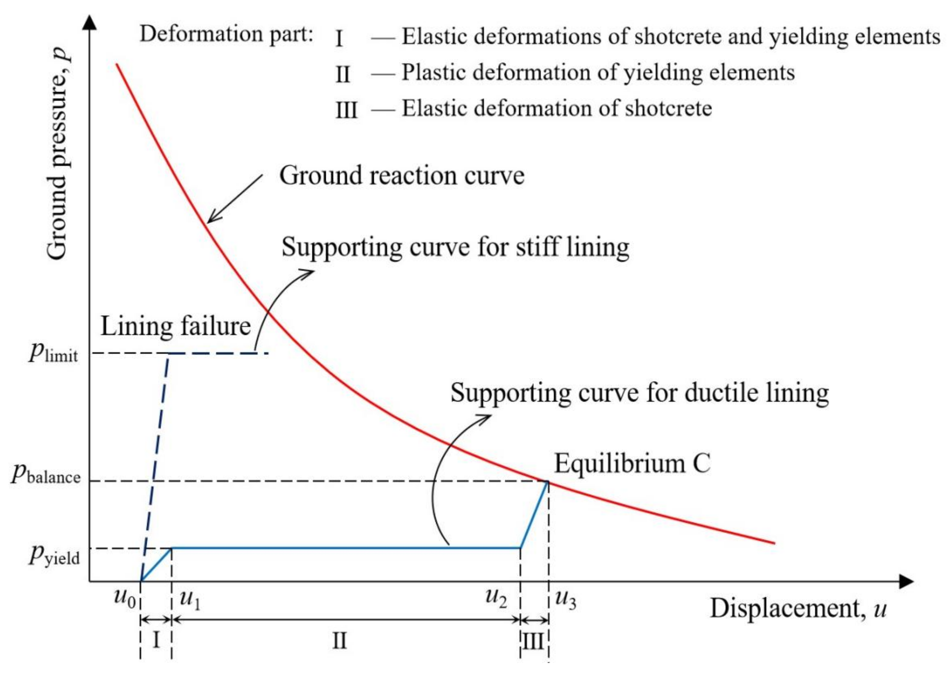
2. Supporting Mechanism and Benefits of Ductile Linings
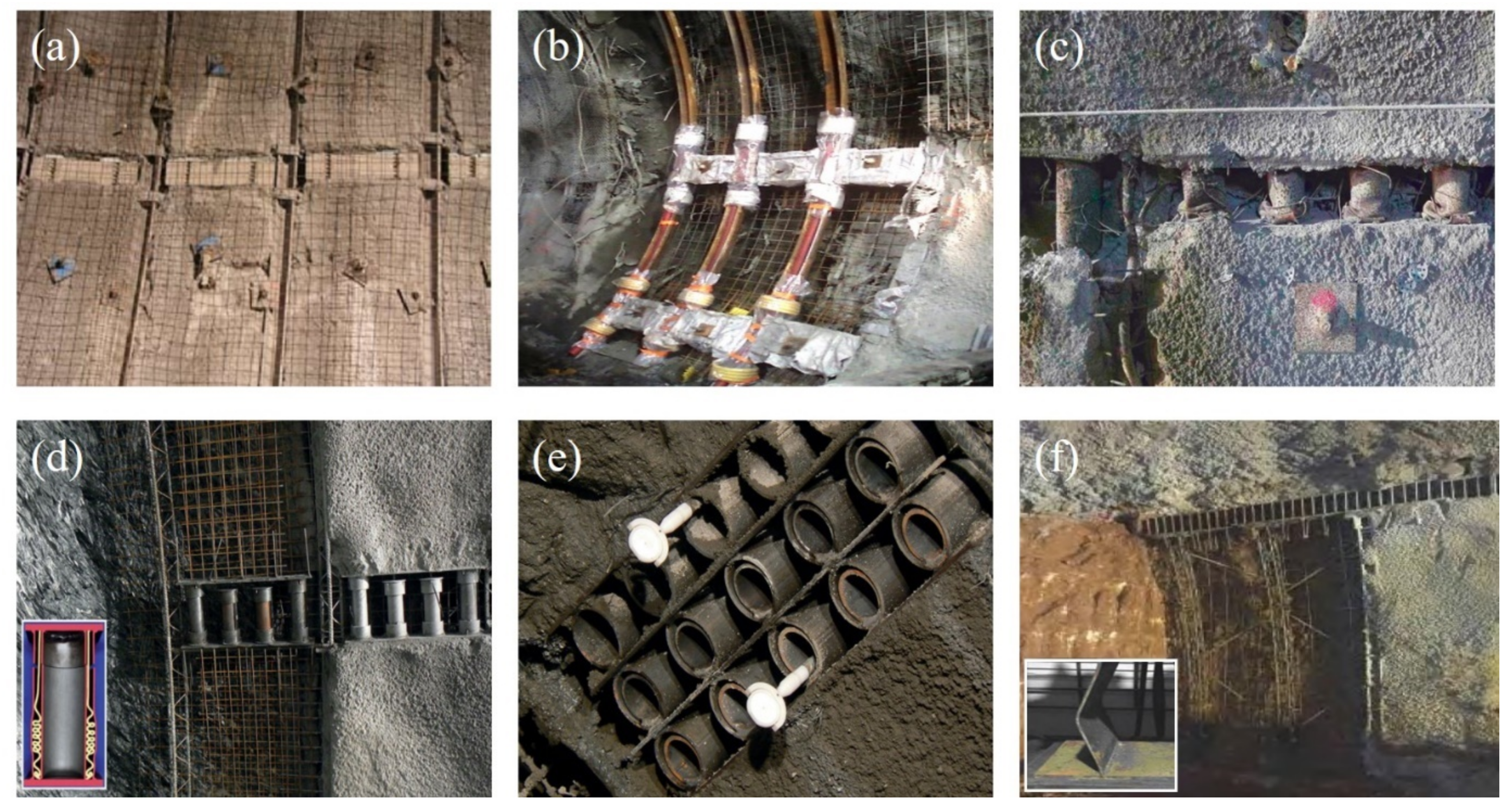
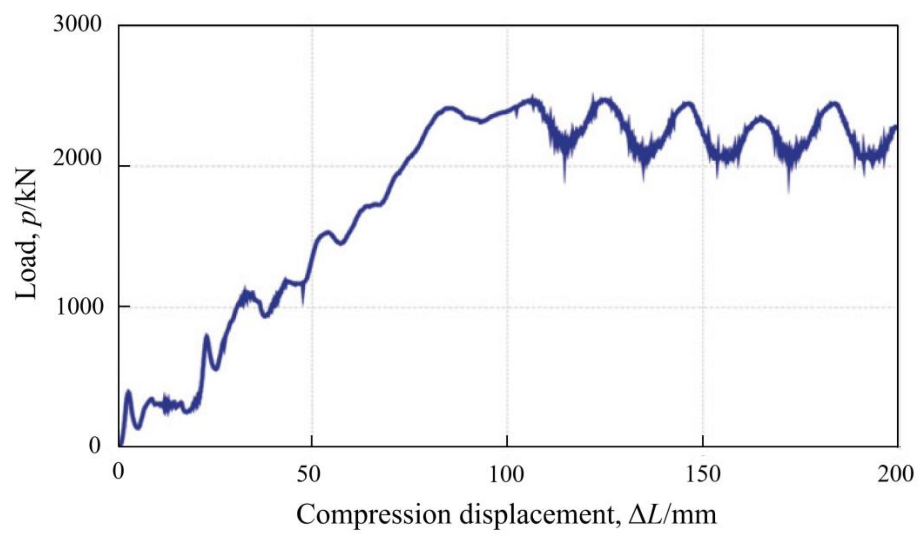
3. Main Types of Yielding Elements
3.1. Highly Deformable Concrete (Hidcon) Element
3.2. Lining Stress Controller Element
3.3. Wabe Element
3.4. Support Resistance Limiting Damper
4. Mechanical Performance for Ductile Linings
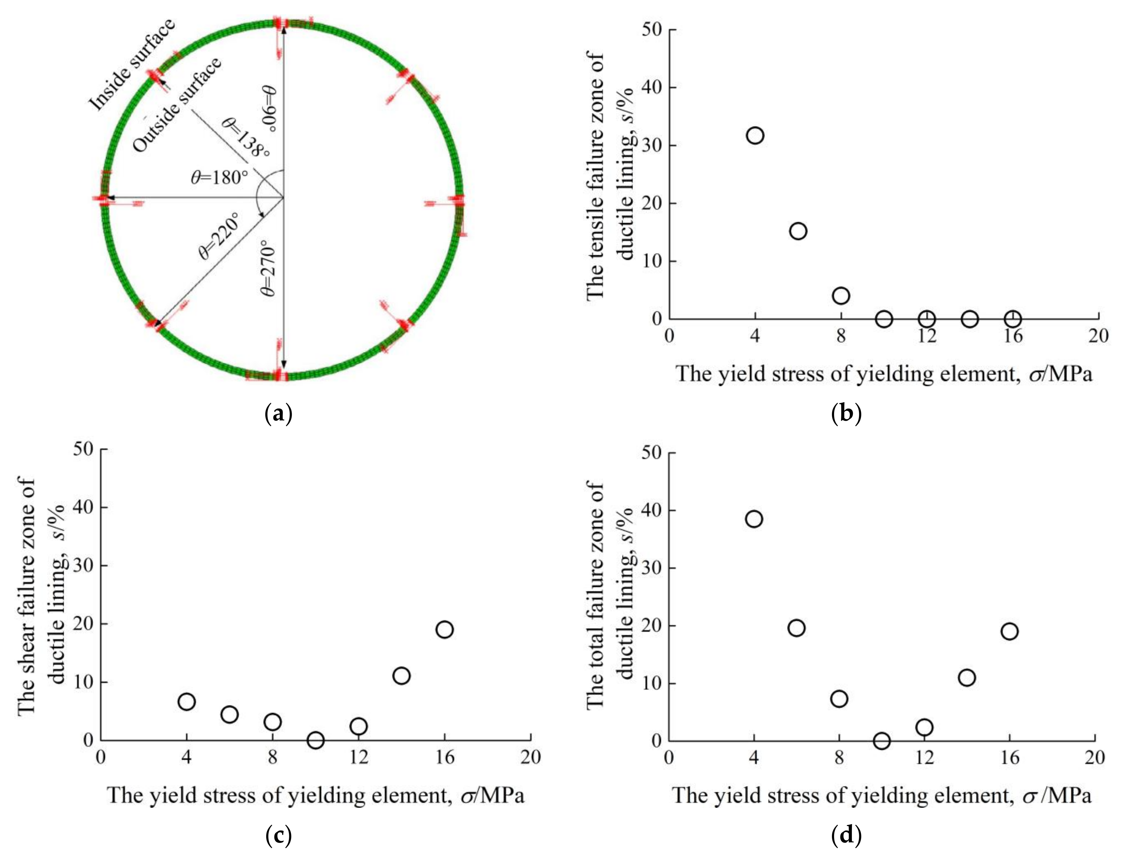
4.1. Factors Influencing the Performance of Ductile Linings
4.2. Design Method for Ductile Linings
5. Challenges and Directions for Future Research
- Development of higher performance yielding elements, making them harmoniously work with progressive hardening shotcrete;
- Establishment of rock quality evaluation system, making it quick and easy to judge the applicability of ductile linings in such grounds;
- Development of universal ductile lining design method, leading to its wider applications in squeezing rock tunnels;
- How to determine the interface interaction between rock and ductile lining, especially in the situation of anisotropic ground stress;
- How to accurately predict the tunnel convergence with ductile lining parameters selected, so as to tunnel over-excavation in advance;
- How to qualitatively determine the influence of ductile lining parameters on its performance, such as shotcrete hardening, yielding element installation location, and yield stress;
- How to repair ductile linings during construction or service, with unexpected failure occurring.
6. Conclusions
Author Contributions
Funding
Institutional Review Board Statement
Informed Consent Statement
Data Availability Statement
Conflicts of Interest
References
- Tran-Manh, H.; Sulem, J.; Subrin, D. Progressive degradation of rock properties and time-dependent behavior of deep tunnels. Acta Geotech. 2016, 11, 693–711. [Google Scholar] [CrossRef]
- Vrakas, A.; Anagnostou, G. Ground Response to Tunnel Re-profiling Under Heavily Squeezing Conditions. Rock Mech. Rock Eng. 2016, 49, 2753–2762. [Google Scholar] [CrossRef]
- Wu, K.; Shao, Z.; Qin, S.; Li, B. Determination of Deformation Mechanism and Countermeasures in Silty Clay Tunnel. J. Perform. Constr. Facil. 2020, 34, 04019095. [Google Scholar] [CrossRef]
- Iasiello, C.; Torralbo, J.C.G.; Fernández, C.T. Large deformations in deep tunnels excavated in weak rocks: Study on Y-Basque high-speed railway tunnels in northern Spain. Undergr. Space 2021, 6, 636–649. [Google Scholar] [CrossRef]
- Xu, C.; Xia, C. A new large strain approach for predicting tunnel deformation in strain-softening rock mass based on the generalized Zhang-Zhu strength criterion. Int. J. Rock Mech. Min. Sci. 2021, 143, 104786. [Google Scholar] [CrossRef]
- Chu, Z.; Wu, Z.; Liu, Q.; Liu, B.; Sun, J. Analytical Solution for Lined Circular Tunnels in Deep Viscoelastic Burgers Rock Considering the Longitudinal Discontinuous Excavation and Sequential Installation of Liners. J. Eng. Mech. 2021, 147, 04021009. [Google Scholar] [CrossRef]
- Nistor, M.M.; Rahardjo, H.; Satyanaga, A.; Hao, K.Z.; Xiaosheng, Q.; Sham, A.W.L. Investigation of groundwater table distribution using borehole piezometer data interpolation: Case study of Singapore. Eng. Geol. 2020, 271, 105590. [Google Scholar] [CrossRef]
- Kontogianni, V.; Psimoulis, P.; Stiros, S. What is the contribution of time-dependent deformation in tunnel convergence? Eng. Geol. 2006, 82, 264–267. [Google Scholar] [CrossRef]
- Paraskevopoulou, C.; Diederichs, M. Analysis of time-dependent deformation in tunnels using the Convergence-Confinement Method. Tunn. Undergr. Space Technol. 2018, 71, 62–80. [Google Scholar] [CrossRef]
- Zhang, C.; Cui, G.; Zhang, Y.; Zhou, H.; Liu, N.; Huang, S. Squeezing deformation control during bench excavation for the Jinping deep soft-rock tunnel. Eng. Fail. Anal. 2020, 116, 104761. [Google Scholar] [CrossRef]
- Wu, K.; Shao, Z.; Qin, S.; Zhao, N.; Chu, Z. An Improved Nonlinear Creep Model for Rock Applied to Tunnel Displacement Prediction. Int. J. Appl. Mech. 2021, 13, 2150094. [Google Scholar] [CrossRef]
- Arora, K.; Gutierrez, M.; Hedayat, A.; Cruz, E.C. Time-Dependent Behavior of the Tunnels in Squeezing Ground: An Experimental Study. Rock Mech. Rock Eng. 2021, 54, 1755–1777. [Google Scholar] [CrossRef]
- Chu, Z.; Wu, Z.; Wang, Z.; Weng, L.; Liu, Q.; Fan, L. Micro-mechanism of brittle creep in saturated sandstone and its mechanical behavior after creep damage. Int. J. Rock Mech. Min. Sci. 2021, 149, 104994. [Google Scholar] [CrossRef]
- Hu, B.; Sharifzadeh, M.; Feng, X.-T.; Guo, W.; Talebi, R. Role of stress, slenderness and foliation on large anisotropic deformations at deep underground excavations. Int. J. Min. Sci. Technol. 2021, 31, 577–590. [Google Scholar] [CrossRef]
- Zhao, N.; Shao, Z.; Wu, K.; Chu, Z.; Qin, S. Time-Dependent Solutions for Lined Circular Tunnels Considering Rockbolts Reinforcement and Face Advancement Effects. Int. J. Géoméch. 2021, 21, 04021179. [Google Scholar] [CrossRef]
- Kurokawa, S.; Masumoto, K.; Koizumi, Y.; Okada, Y.; Utsuno, M. Evaluation of deformable support in squeezing ground by experiment and numerical analysis. In Proceedings of the 5th ISRM Young Scholars’ Symposium on Rock Mechanics and International Symposium on Rock Engineering for Innovative Future, Okinawa, Japan, 1–4 December 2019. [Google Scholar]
- Wu, K.; Shao, Z.; Sharifzadeh, M.; Chu, Z.; Qin, S. Analytical Approach to Estimating the Influence of Shotcrete Hardening Property on Tunnel Response. J. Eng. Mech. 2022, 148, 04021127. [Google Scholar] [CrossRef]
- Kovári, K. Design methods with yielding support in squeezing and swelling rocks. In Proceedings of the World Tunnel Congress, Budapest, Hungary, 23–28 May 2009. [Google Scholar]
- Schubert, W. Dealing with squeezing conditions in Alpine tunnels. Rock Mech. Rock Eng. 1996, 29, 145–153. [Google Scholar] [CrossRef]
- Ortlepp, W.; Stacey, T. Performance of tunnel support under large deformation static and dynamic loading. Tunn. Undergr. Space Technol. 1998, 13, 15–21. [Google Scholar] [CrossRef]
- Öge, I.F. Revisiting the assessment of squeezing condition and energy absorption of flexible supports: A mine development case. Tunn. Undergr. Space Technol. 2021, 108, 103712. [Google Scholar] [CrossRef]
- Wu, K.; Shao, Z. Study on the Effect of Flexible Layer on Support Structures of Tunnel Excavated in Viscoelastic Rocks. J. Eng. Mech. 2019, 145, 04019077. [Google Scholar] [CrossRef]
- Lackner, R.; Macht, J.; Hellmich, C.; Mang, H.A. Hybrid Method for Analysis of Segmented Shotcrete Tunnel Linings. J. Geotech. Geoenvironmental Eng. 2002, 128, 298–308. [Google Scholar] [CrossRef]
- Radončić, N.; Schubert, W.; Moritz, B. Ductile support design. Géoméch. Und Tunn. 2009, 2, 561–577. [Google Scholar] [CrossRef]
- Mezger, F.; Ramoni, M.; Anagnostou, G. Options for deformable segmental lining systems for tunnelling in squeezing rock. Tunn. Undergr. Space Technol. 2018, 76, 64–75. [Google Scholar] [CrossRef]
- Wu, K.; Shao, Z.; Qin, S.; Zhao, N. Mechanical analysis of tunnels supported by yieldable steel ribs in rheological rocks. Geomech. Eng. 2019, 19, 61–70. [Google Scholar] [CrossRef]
- Hammer, A.L.; Thewes, M. Integration of yielding elements in various computational methods for calculations in different planning and construction phases. In Proceedings of the ITA-AITES World Tunnel Congress, Dubai, United Arab Emirates, 21–26 April 2018. [Google Scholar]
- Ghorbani, M.; Shahriar, K.; Sharifzadeh, M.; Masoudi, R. A critical review on the developments of rock support systems in high stress ground conditions. Int. J. Min. Sci. Technol. 2020, 30, 555–572. [Google Scholar] [CrossRef]
- Fan, S.; Song, Z.; Xu, T.; Wang, K.; Zhang, Y. Tunnel deformation and stress response under the bilateral foundation pit construction: A case study. Arch. Civ. Mech. Eng. 2021, 21, 109. [Google Scholar] [CrossRef]
- Schubert, W.; Brunnegger, S.; Staudacher, R.; Wenger, J. Further development of yielding elements and connecting elements for shotcrete. Géoméch. Und Tunn. 2018, 11, 575–581. [Google Scholar] [CrossRef]
- Barla, G.; Bonini, M.; Semeraro, M. Analysis of the behaviour of a yield-control support system in squeezing rock. Tunn. Undergr. Space Technol. 2011, 26, 146–154. [Google Scholar] [CrossRef]
- Qiu, W.; Wang, G.; Gong, L.; Shen, Z.; Li, C.; Dang, J. Research and application of resistance-limiting and energy-dissipating support in large deformation tunnel. Chin. J. Rock Mech. Eng. 2018, 37, 1785–1795. [Google Scholar] [CrossRef]
- Deng, Y.; Xie, J.; Li, S. Research and Application of Support Resistant Limiting Dampers in the Deep-Buried Large-Section Loess Tunnel. Adv. Civ. Eng. 2020, 2020, 8841703. [Google Scholar] [CrossRef]
- Entfellner, M.; Hamdi, P.; Wang, X.; Wannenmacher, H.; Amann, F. Temporary Removal: Investigating High-Strength Expanded Polystyrene (HS-EPS) as yielding support elements for tunnelling in squeezing ground conditions. Tunn. Undergr. Space Technol. 2021, 118, 104186. [Google Scholar] [CrossRef]
- Wu, K.; Shao, Z.; Qin, S.; Wei, W.; Chu, Z. A critical review on the performance of yielding supports in squeezing tunnels. Tunn. Undergr. Space Technol. 2021, 115, 103815. [Google Scholar] [CrossRef]
- Verient, M.; Kluckner, A.; Radoncic, N.; Schubert, W. Investigations on telescope yielding elements with porous filling. In Proceedings of the ISRM Regional Symposium-EUROCK, Salzburg, Austria, 7–10 October 2015. [Google Scholar]
- Moritz, B. Yielding elements—Requirements, overview and comparison/Stauchelemente—Anforderungen, Überblick und Vergleich. Géoméch. Und Tunn. 2011, 4, 221–236. [Google Scholar] [CrossRef]
- Weidinger, F.; Lauffer, H. The Tauern tunnel first and second tubes from the contractor’s viewpoint. Géoméch. Und Tunn. 2009, 2, 24–32. [Google Scholar] [CrossRef]
- Bonini, M.; Barla, G. The Saint Martin La Porte access adit (Lyon–Turin Base Tunnel) revisited. Tunn. Undergr. Space Technol. 2012, 30, 38–54. [Google Scholar] [CrossRef]
- Li, C.; Wang, G.; Qiu, W.; Gong, L.; Zhao, Y.; Wang, Q. Research and application of support resistant limiting dampers in the tunnel with high horizontal geostress. Mod. Tunn. Tech. 2020, 57, 15–24. [Google Scholar] [CrossRef]
- Moritz, B. Ductile Support System for Tunnels in Squeezing Rock. Ph.D. Thesis, Graz University of Technology, Graz, Austria, 1999. [Google Scholar]
- Kolymbas, D. Stress and deformation fields around a deep circular tunnel. In Tunnelling and Tunnel Mechanics: A Rational Approach to Tunnelling; Springer: Berlin/Heidelberg, Germany, 2005; pp. 273–306. [Google Scholar]
- Merlini, D.; Stocker, D.; Falanesca, M.; Schuerch, R. The Ceneri Base Tunnel: Construction Experience with the Southern Portion of the Flat Railway Line Crossing the Swiss Alps. Engineering 2018, 4, 235–248. [Google Scholar] [CrossRef]
- Bhavsar, H.; Dinis, A.; Fernandes, E.M.; Antunes, P.; Melâneo, F. Design and construction of tunnels in zones subjected to high convergences. In Proceedings of the World Tunnel Congress, São Paulo, Brazil, 9–14 May 2014. [Google Scholar]
- Schubert, W.; Brunnegger, S. New ductile tunnel lining system. In Proceedings of the World Tunnel Congress, Bergen, Norway, 9–15 June 2017. [Google Scholar]
- Hasanpour, R.; Hammer, A.L.; Thewes, M. Analysis of multilateral interaction between shotcrete, yielding support and squeezing ground by means of two different numerical methods. In Proceedings of the ITA-AITES World Tunnel Congress, Dubai, United Arab Emirates, 21–25 April 2018. [Google Scholar]
- Button, E.A.; Schubert, W.; Moritz, B. The application of ductile support methods in Alpine tunnels. In Proceedings of the 10th ISRM Congress, Sandton, South Africa, 8–12 September 2003. [Google Scholar]
- Anagnostou, G.; Cantieni, L. Design and analysis of yielding support in squeezing ground. In Proceedings of the 11th ISRM Congress, Lisbon, Portugal, 9–13 July 2007. [Google Scholar]
- Radoncic, N.; Schubert, W. Calculation of the shotcrete utilization for lining with integrated yielding elements. In Proceedings of the ISRM International Symposium on Rock Mechanics-SINOROCK 2009, Hong Kong, China, 1922 May 2009. [Google Scholar]
- Radoncic, N.; Schubert, W. System behaviour in weak ground: Comparison of yielding elements. In Proceedings of the 12th ISRM Congress, Beijing, China, 16–21 October 2011. [Google Scholar]
- Li, C.C. Development trend of underground rock support. In Proceedings of the 13th ISRM Congress, Montreal, QC, Canada, 10–13 May 2015. [Google Scholar]
- Thut, A.; Naterop, D.; Steiner, P.; Stolz, M. Tunnelling in squeezing rock-yielding elements and face control. In Proceedings of the 8th International Symposium on Tunnel Construction and Underground Structures, Lubljana, Slovenia, 15–30 October 2006. [Google Scholar]
- Schubert, W. Design of ductile tunnel linings. In Proceedings of the 42nd US Rock Mechanics Symposium (USRMS), San Francisco, CA, USA, 29 June–2 July 2008. [Google Scholar]
- Hammer, A.L.; Hasanpour, R.; Hoffmann, C.; Thewes, M. Numerical analysis of interaction behavior of yielding supports in squeezing ground. In Proceedings of the 9th European Conference on Numerical Methods in Geotechnical Engineering, Porto, Portugal, 25–27 June 2018. [Google Scholar]
- Schubert, W.; Radoncic, N. Tunnelling in “Squeezing” ground conditions-problems and solutions. In Proceedings of the 13th ISRM International Congress of Rock Mechanics, Montreal, QC, Canada, 10–13 May 2015. [Google Scholar]
- Ramoni, M.; Anagnostou, G. The Interaction Between Shield, Ground and Tunnel Support in TBM Tunnelling Through Squeezing Ground. Rock Mech. Rock Eng. 2010, 44, 37–61. [Google Scholar] [CrossRef]
- Tian, H.; Chen, W.; Yang, D.; Wu, G.; Tan, X. Numerical analysis on the interaction of shotcrete liner with rock for yielding supports. Tunn. Undergr. Space Technol. 2016, 54, 20–28. [Google Scholar] [CrossRef]
- Tian, H.; Chen, W.; Tan, X.; Yang, D.; Wu, G.; Yu, J. Numerical investigation of the influence of the yield stress of the yielding element on the behaviour of the shotcrete liner for yielding support. Tunn. Undergr. Space Technol. 2018, 73, 179–186. [Google Scholar] [CrossRef]
- Radončić, N.; Schubert, W. Novel method for ductile lining pre-design. Geomech. Tunn. 2011, 4, 195–210. [Google Scholar] [CrossRef]
- Wu, K.; Shao, Z.; Qin, S.; Zhao, N.; Hu, H. Analytical-based assessment of effect of highly deformable elements on tunnel lining within viscoelastic rocks. Int. J. Appl. Mech. 2020, 12, 2050030. [Google Scholar] [CrossRef]
- Cantieni, L.; Anagnostou, G. The interaction between yielding supports and squeezing ground. Tunn. Undergr. Space Technol. 2009, 24, 309–322. [Google Scholar] [CrossRef]
- Lei, S.X.; Zhao, W. Study on the mechanism of circumferential yielding support for soft rock tunnel with large deformation. Rock Soil Mech. 2020, 41, 1039–1047. [Google Scholar] [CrossRef]
- Wu, K.; Shao, Z.; Qin, S. An analytical design method for ductile support structures in squeezing tunnels. Arch. Civ. Mech. Eng. 2020, 20, 1–13. [Google Scholar] [CrossRef]
- Gschwandtner, G.G.; Galler, R. Input to the application of the convergence confinement method with time-dependent material behaviour of the support. Tunn. Undergr. Space Technol. 2012, 27, 13–22. [Google Scholar] [CrossRef]
- Fan, S.; Song, Z.; Xu, T.; Zhang, Y. Investigation of the microstructure damage and mechanical properties evolution of limestone subjected to high-pressure water. Constr. Build. Mater. 2021, 316, 125871. [Google Scholar] [CrossRef]
- Asef, M.; Reddish, D.; Lloyd, P. Rock–support interaction analysis based on numerical modelling. Geotech. Geol. Eng. 2000, 18, 23–37. [Google Scholar] [CrossRef]
- Sun, Y.; Bi, R.; Chang, Q.; Taherdangkoo, R.; Zhang, J.; Sun, J.; Huang, J.; Li, G. Stability Analysis of Roadway Groups under Multi-Mining Disturbances. Appl. Sci. 2021, 11, 7953. [Google Scholar] [CrossRef]
- Barla, G. Squeezing rocks in tunnels. Int. Soc. Rock Mech. News J. 1995, 2, 44–49. [Google Scholar]
- Chu, Z.; Wu, Z.; Liu, Q.; Liu, B. Analytical Solutions for Deep-Buried Lined Tunnels Considering Longitudinal Discontinuous Excavation in Rheological Rock Mass. J. Eng. Mech. 2020, 146, 04020047. [Google Scholar] [CrossRef]
- Rabcewicz, L.V. Gebirgsdruck und Tunnelbau; Springer: Berlin/Heidelberg, Germany, 1994. [Google Scholar]
- Hoek, E.; Guevara, R. Overcoming Squeezing in the Yacambú-Quibor Tunnel, Venezuela. Rock Mech. Rock Eng. 2009, 42, 389–418. [Google Scholar] [CrossRef]
- Krastanov, G.; Daller, J.; Preh, A. Tunnel design in squeezing rock conditions with high overburden. In Proceedings of the 28th ITA General Assembly and World Tunnel Congress, Sydney, Australia, 2–8 March 2002. [Google Scholar]
- Wu, K.; Shao, Z.; Hong, S.; Qin, S. Analytical solutions for mechanical response of circular tunnels with double primary linings in squeezing grounds. Geomech. Eng. 2020, 22, 509–518. [Google Scholar] [CrossRef]
- Barla, G. Full-face excavation of large tunnels in difficult conditions. J. Rock Mech. Geotech. Eng. 2016, 8, 294–303. [Google Scholar] [CrossRef] [Green Version]
- Wu, K.; Shao, Z. Visco-Elastic Analysis on the Effect of Flexible Layer on Mechanical Behavior of Tunnels. Int. J. Appl. Mech. 2019, 11, 1950027. [Google Scholar] [CrossRef]
- Sakai, K.; Schubert, W. Study on ductile support system by means of convergence confinement method. In Proceedings of the 5th ISRM Young Scholars’ Symposium on Rock Mechanics and International Symposium on Rock Engineering for Innovative Future, Okinawa, Japan, 1–4 December 2019. [Google Scholar]
- Chu, Z.; Wu, Z.; Liu, B.; Liu, Q. Coupled analytical solutions for deep-buried circular lined tunnels considering tunnel face advancement and soft rock rheology effects. Tunn. Undergr. Space Technol. 2019, 94, 103111. [Google Scholar] [CrossRef]
- Wu, K.; Shao, Z.; Qin, S. A solution for squeezing deformation control in tunnels using foamed concrete: A review. Constr. Build. Mater. 2020, 257, 119539. [Google Scholar] [CrossRef]
- Barla, G.; Debernardi, D.; Sterpi, D. Time-Dependent Modeling of Tunnels in Squeezing Conditions. Int. J. Géoméch. 2012, 12, 697–710. [Google Scholar] [CrossRef]
- Xu, C.; Xia, C.; Du, S. Simplified solution for viscoelastic-plastic interaction between tunnel support and surrounding rock based on MC and GZZ strength criteria. Comput. Geotech. 2021, 139, 104393. [Google Scholar] [CrossRef]
- Sun, Y.; Li, G.; Zhang, J.; Huang, J. Rockburst intensity evaluation by a novel systematic and evolved approach: Machine learning booster and application. Bull. Int. Assoc. Eng. Geol. 2021, 80, 8385–8395. [Google Scholar] [CrossRef]
- Cebasek, T.M.; Likara, J. A three-dimensional static numerical model of a complex underground structure in high squeezing ground. Acta Geotech. Slov. 2015, 12, 4–15. [Google Scholar]
- Schubert, W.; Moritz, B. Controllable ductile support system for tunnels in squeezing rock. Felsbau 1998, 16, 224–227. [Google Scholar]
- Schubert, W.; Radoncic, N. New yielding elements for tunnel linings: Design requirements, layout and influence on system behavior. In Proceedings of the ISRM International Symposium-EUROCK 2013, Wroclaw, Poland, 23–24 September 2013. [Google Scholar]
- Wu, K.; Shao, Z.; Sharifzadeh, M.; Hong, S.; Qin, S. Analytical computation of support characteristic curve for circumferential yielding lining in tunnel design. J. Rock Mech. Geotech. Eng. 2021, 14, 854. [Google Scholar] [CrossRef]
- Dalgic, S. Tunneling in squeezing rock, the Bolu tunnel, Anatolian Motorway, Turkey. Eng. Geol. 2002, 67, 73–96. [Google Scholar] [CrossRef]
- Wu, K.; Shao, Z.; Qin, S. Study on the interaction mechanism between surrounding rock and liner with yielding elements in squeezing tunnels. Eng. Mech. 2020, 37, 1–10. [Google Scholar] [CrossRef]
- Cristescu, N.; Fotǎ, D.; Medveş, E. Tunnel support analysis incorporating rock creep. Int. J. Rock Mech. Min. Sci. Géoméch. Abstr. 1987, 24, 321–330. [Google Scholar] [CrossRef]
- Liu, Y.; Sulem, J.; Subrin, D.; Tran-Manh, H.; Humbert, E. Time-Dependent Behavior of Saint-Martin-La-Porte Exploratory Galleries: Field Data Processing and Numerical Modeling of Excavation in Squeezing Rock Conditions. Int. J. Géoméch. 2021, 21, 04021239. [Google Scholar] [CrossRef]
- Yan, Q.; Li, S.C.; Xie, C.; Li, Y. Analytical Solution for Bolted Tunnels in Expansive Loess Using the Convergence-Confinement Method. Int. J. Géoméch. 2018, 18, 04017124. [Google Scholar] [CrossRef]


| Tunnel Name | Country | Reference |
|---|---|---|
| Galgenberg tunnel | Austria | [30] |
| Semmering pilot tunnel | Austria | [41] |
| Strengen tunnel | Austria | [42] |
| Tauern tunnel | Austria | [38] |
| Koralm tunnel | Austria | [37] |
| Lyon-Torino Base tunnel | Italy | [31,39] |
| Ibbenbüren coal mine tunnel | Germany | [25] |
| Lötschberg Base tunnel | Switzerland | [18] |
| Ceneri Base tunnel | Switzerland | [43] |
| Yangshan tunnel | China | [32,33,40] |
| Support System | Item | Specification | Quantity/m2 | Unit | Unit Price (Euro) | Cost (Euro) | |
|---|---|---|---|---|---|---|---|
| Stiff support system | Shotcrete | 1st layer | t = 250 mm, 36 N/mm2 | 17.997 | m3 | 115 | 2070 |
| 2nd layer | t = 200 mm, 36 N/mm2 | 13.549 | m3 | 115 | 1558 | ||
| Steel support | 1st layer | NH-200 | 1.996 | ton | 969 | 1934 | |
| 2nd layer | NH-150 | 1.170 | ton | 969 | 1134 | ||
| Rock bolt | 1st layer | L = 6 m, 290 kN | 21 | piece | 42 | 882 | |
| Wire mesh | 1st layer | Ground side of lining d5 mm × 150 mm spacing | 51.788 | m2 | 1.58 | 82 | |
| 2nd layer | 48.596 | m2 | 1.58 | 77 | |||
| Yielding element | - | piece | 0 | 0 | |||
| Sum | 7737 | ||||||
| Ductile support system | Shotcrete | t = 250 mm, 36 N/mm2 | 17.341 | m3 | 115 | 2005 | |
| Steel support | Lattice girder | 0.484 | ton | 920 | 445 | ||
| Rock bolt | L = 6 m, 290 kN | 21 | piece | 42 | 882 | ||
| Wire mesh | Inner side | Both sides of lining d5 mm × 150 mm spacing | 50.192 | m2 | 1.58 | 79 | |
| Outer side | 48.197 | m2 | 1.58 | 79 | |||
| Yielding element | LSC-N | 4 | piece | 400 | 1600 | ||
| Sum | 5087 | ||||||
| Support System | Item | Specification | Quantity/m2 | Unit | Unit Price (Euro) | Cost (Euro) | |
|---|---|---|---|---|---|---|---|
| Stiff support system | Shotcrete | 1st layer | t = 250 mm, 36 N/mm2 | 21.308 | m3 | 115 | 2450 |
| 2nd layer | t = 200 mm, 36 N/mm2 | 16.555 | m3 | 115 | 1904 | ||
| Steel support | 1st layer | NH-200 | 2.208 | ton | 1208 | 2450 | |
| 2nd layer | NH-150 | 1.361 | ton | 1208 | 1644 | ||
| Rock bolt | 1st layer | L = 6 m, 290 kN | 25 | piece | 42 | 1050 | |
| Wire mesh | 1st layer | Ground side of lining d5 mm × 150 mm spacing | 51.309 | m2 | 1.58 | 81 | |
| 2nd layer | 47.718 | m2 | 1.58 | 75 | |||
| Yielding element | - | piece | 0 | 0 | |||
| Sum | 9654 | ||||||
| Ductile support system | Shotcrete | t = 250 mm, 36 N/mm2 | 20.459 | m3 | 115 | 2353 | |
| Steel support | Lattice girder | 0.474 | ton | 920 | 436 | ||
| Rock bolt | L = 6 m, 290 kN | 25 | piece | 42 | 1050 | ||
| Wire mesh | Inner side | Both sides of lining d5 mm × 150 mm spacing | 49.314 | m2 | 1.58 | 78 | |
| Outer side | 46.920 | m2 | 1.58 | 74 | |||
| Yielding element | LSC-N | 6 | piece | 400 | 2400 | ||
| Sum | 6391 | ||||||
| Criterion | HidCon | LSC | Wabe | SRLD |
|---|---|---|---|---|
| Deformability | Medium | High | High | High |
| Initial stiffness | High | Medium | Low | High |
| Yield stress | Medium | High | Low | Low |
| Installation procedure | Medium | Medium | Medium | Simple |
| Serviceability | Difficult | Difficult | Difficult | Difficult |
| Costs | Low | Low | Medium | Low |
| Chainage | 1325–1444 | 1445–1601 | 1602–1747 | 1716–1747 | 174–1777 |
|---|---|---|---|---|---|
| Number and position | 8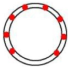 | 9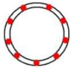 | 7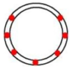 | 6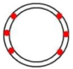 | 4 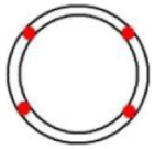 |
| Chainage | 1778–1784 | 1785–1820 | 1821–1853 | 1854–1886 | 1887–1915 |
| Number and position | 2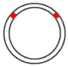 | 4 | 6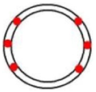 | 4 | 2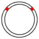 |
| Support System | Shotcrete Thickness d1/cm | Arch Type | Yielding Elements | Material | Length d2/cm | Illustration |
|---|---|---|---|---|---|---|
| Number × Yielding Deformation/cm | ||||||
| Rigid support | - | - | - | - | - | 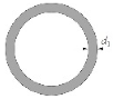 |
| RS15 | 15 | TH36 | - | - | - | |
| RS25 | 25 | TH36 | - | - | - | |
| Ductile lining | - | - | - | - | - | 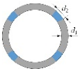 |
| YS15/S5 | 15 | TH36 | 4 × 5.0 | Styrofoam | 5 | |
| YS15/C5 | 15 | TH36 | 4 × 2.5 | Concrete | 5 | |
| YS15/C15 | 15 | TH36 | 4 × 7.5 | Concrete | 15 | |
| YS25/C15 | 25 | TH36 | 4 × 7.5 | Concrete | 15 |
Publisher’s Note: MDPI stays neutral with regard to jurisdictional claims in published maps and institutional affiliations. |
© 2022 by the authors. Licensee MDPI, Basel, Switzerland. This article is an open access article distributed under the terms and conditions of the Creative Commons Attribution (CC BY) license (https://creativecommons.org/licenses/by/4.0/).
Share and Cite
Zheng, X.; Wu, K.; Shao, Z.; Yuan, B.; Zhao, N. Tunnel Squeezing Deformation Control and the Use of Yielding Elements in Shotcrete Linings: A Review. Materials 2022, 15, 391. https://doi.org/10.3390/ma15010391
Zheng X, Wu K, Shao Z, Yuan B, Zhao N. Tunnel Squeezing Deformation Control and the Use of Yielding Elements in Shotcrete Linings: A Review. Materials. 2022; 15(1):391. https://doi.org/10.3390/ma15010391
Chicago/Turabian StyleZheng, Xiaomeng, Kui Wu, Zhushan Shao, Bo Yuan, and Nannan Zhao. 2022. "Tunnel Squeezing Deformation Control and the Use of Yielding Elements in Shotcrete Linings: A Review" Materials 15, no. 1: 391. https://doi.org/10.3390/ma15010391
APA StyleZheng, X., Wu, K., Shao, Z., Yuan, B., & Zhao, N. (2022). Tunnel Squeezing Deformation Control and the Use of Yielding Elements in Shotcrete Linings: A Review. Materials, 15(1), 391. https://doi.org/10.3390/ma15010391