Abstract
Strain is a crucial assessment parameter in structural health monitoring systems. Microstrip sensors have been one of the new types of sensors used to measure this parameter in recent years. So far, the strain directionality of these sensors and the methods of miniaturization have been studied. This article proposes the use of a single cell metamaterial as a resonator of the microstrip sensor excited through the microstrip line. The proposed solution allowed for significant miniaturization of the microstrip sensor, with just a slight decrease in sensitivity. The proposed sensor can be used to measure local deformation values and in places with a small access area. The presented sensor was validated using numerical and experimental methods. In addition, it was compared with a reference (rectangular geometry) microstrip sensor.
1. Introduction
The safety and integrity of infrastructure is an important aspect of building and maintaining activities. Therefore, Structural Health Monitoring (SHM) systems are becoming more and more popular. SHM systems support or even replace periodic structural condition inspections. The implementation of SHM in various structures is beneficial in many ways such as increasing public safety, cutting costs of exploitation and monitoring, improving the life span of constructions, and early detection of risks. This leads to improvement of the examined object’s overall performance [1]. Large dimensions of structures, fancy shapes, new building materials, as well as monitoring of old structures have resulted in increased expenses on SHM systems and their development. Extensive research is being carried out to improve efficiency and reduce the cost of SHM systems. In particular, research is conducted on the topics of new sensors, communication of system components, and data processing including exploitation time estimation.
Strain sensors are a crucial component in most sensor networks used to monitor civil structures. In the case of bridge condition monitoring systems, about 50% of all sensors are strain sensing elements [2]. The stress measurement of steel structures is performed in two ways. The first method is the analysis of the magnetic properties of steel using a magnetic sensor [3]. The second option is to use a sensor attached to the tested structure. The sensor output signal depends on the deformation. Until now, stress sensors have been invented using various physical phenomena. The first strain gauge was the proposed and commercialized resistance strain gauge by Edward E. Simons and Arthur C. Ruge [4]. The operating principle of a resistance strain gauge is based on the changes in a conductor’s electrical resistance as a result of changes in its cross-sectional area and length. The resistance value of the sensor increases as it is stretched. The change in the resistance of a semiconductor element is used in piezoresistive sensors. In this case, the crystal lattice of the semiconductor is distorted, which affects the energy bands [5]. Utilization of the piezoelectric effect in the strain sensor is presented in [6]. In the case of FBG (Fiber Bragg Grating) sensors, deformation changes the length of the reflected light patch [7].
Microstrip antennas for strain measurements have been proposed and developed in recent years [8,9,10,11,12,13,14,15,16,17,18,19,20,21,22,23,24,25]. The vector network analyzer (VNA) measures the frequency domain reflection coefficient (S11) of the microstrip antenna sensor. The entire measurement system should be considered as a uniform transmission line. All components of the system (VNA port, coaxial wires, SMA connector, microstrip line) have the same impedance (usually equal to 50 Ohms). When a transmission line is loaded with wave impedance, the signal given at the input is not reflected. Planar microwave resonators (patch, radiating part of antenna sensor) have an impedance equal to the wave impedance at resonant frequencies. The resonant frequency depends on the shape and size of the patch. Changing the shape of the patch (i.e., because of external strain) changes the resonant frequency. In this type of sensor, the reflection coefficient as a function of frequency is monitored to determine the deformation based on the resonant frequency shifts. The sensors were fed in wired form [8,9,10,11,12,13,14,16,17,18,19,20,22,24,25] and wireless [15,21,23]. The first and most studied sensor geometry is the rectangular microstrip strain sensor [8,9,10,11,12,18,19,20,21,24]. This geometry provides the highest sensitivity at a given resonance frequency. In the work of [24], rectangular microstrip sensors were used to measure deformations. The patches were designed for different resonant frequencies. The following conclusions can be drawn from the study: the higher the resonant frequency, the bigger its shift, and the smaller the size of the sensor. Additionally, circular [13,14,15,25] and other shapes [16,17,22,23,26] of patches were utilized. Other sensor geometries have been developed for the application of local strain measurements or for measuring the direction and value of strain. An important advantage of microstrip sensors is the ability to measure many resonance frequencies with different current density distributions in the patch. This property allows the direction and stress values to be measured using one sensor. For other types of strain gauges, several sensors must be used to measure the direction and strain value. For this purpose, sensors with a rectangular [20] and circular patch [13] and two rectangular patches powered by a T-junction power divider [22] were used.
The patches dimensions range from 0.5λ to 6λ (λ—wavelength) depending on the utilized geometry. Selected applications require a smaller sensor. This necessity results from measurements of local deformation values or in places where there is a small measurement area. Microstrip strain sensors designed for higher operating frequencies are smaller and have higher sensitivity. So it seems that the best way is to design sensors for high resonant frequencies. Notwithstanding, the prices of Vector Network Analyzers strongly depend on their maximum frequency, which makes the use of sensors with very high operating frequencies economically unjustified. Microstrip deformation sensors were miniaturized using the following methods:
- application of a laminate with high electric permittivity [25],
- utilization of a special patch geometry [17].
The work of [25] investigated the sensitivity of circular microstrip strain gauges designed on various laminates. Similar resonant frequency shifts were obtained for all sensors. The use of a high electric permittivity laminate (εr = 13.2) made it possible to significantly reduce the size of the sensor. The patch radius length was 9.68 mm, while for εr = 2.2, the radius length equaled 23.7 mm. Application of the specific patch geometry can also reduce the sensor dimensions. This miniaturization method was carried out by applying the Sierpinski curve fractal in [17]. The sensitivity of the sensor for three iterations of this fractal was tested. The higher the fractal iteration, the smaller the size and sensitivity. For the third iteration of this fractal, the patch size was reduced four times, with a two-fold reduction in sensitivity in relation to the rectangular resonator.
This article presents further research on the miniaturization of microstrip sensors by selecting the appropriate patch geometry. A single metamaterial element was used in this work. Metamaterials are man-made artificial structures that enable material properties to be obtained that do not occur in nature, e.g., negative refractive index n, consequently negative electric permittivity εr and magnetic permittivity µr [26,27,28,29]. They consist of a 2- or 3-dimensional matrix of structural elements (cells) with dimensions several times smaller than the electromagnetic wavelength at which they are supposed to work. Their unique resonance properties can be relatively easily controlled by appropriately designing the geometry of the structural elements. In this work, one of the best-known metamaterial structures—a variant of the split ring resonator (SRR)—was used. In the literature, this variant is called a double split-ring resonator (dSRR). In this work, the proposed sensor was compared with a rectangular microstrip sensor. Numerical calculations and strain measurements were performed in order to evaluate the designed sensors.
2. Sensors Design
In this work, the topic of miniaturization of microstrip sensors has been developed. This is especially important when measuring local strain values or where there is not enough places to attach the sensor. We can reduce the dimensions of the patch by using a patch operating at a higher operating frequency. However, this solution has disadvantageous effects because it is necessary to use a Vector Network Analyzer with a higher measuring frequency range. One of the methods of reducing the size of the sensor is the use of a laminate with high electric permittivity [25]. Another solution is to use the appropriate shape of the patch. The work of [17] uses a patch in the shape of a Sierpinski curve. In this work, it was decided to use a single structural element of the metamaterial as the patch of the microstrip strain sensor. For this purpose, a double Split-Ring Resonator (dSRR) was chosen. This choice resulted from the possibility of easy matching of the patch impedance to the microstrip line using the inset feed. This choice of the impedance matching method resulted from the possibility of limiting the measuring area and the size of the sensor. Narrow-band impedance matching can be also achieved by a quarter wave transformer and stubs. But these solutions increase the size of the sensor and have the potential to affect the accuracy of local strain value measurements. The sensor is designed using an optimization method for a resonant frequency fr = 2.725 GHz.
A rectangular microstrip sensor was designed for the same operating frequency [30]. This assumption avoids the influence of the resonant frequency on the sensitivity of the microstrip transducer. All sensors were designed on glass-reinforced epoxy laminate FR4 (main dielectric parameters: εr = 4.4, tanδ = 0.02). The laminate was 0.18 mm thick. The dimensions of the sensors are shown in Figure 1.
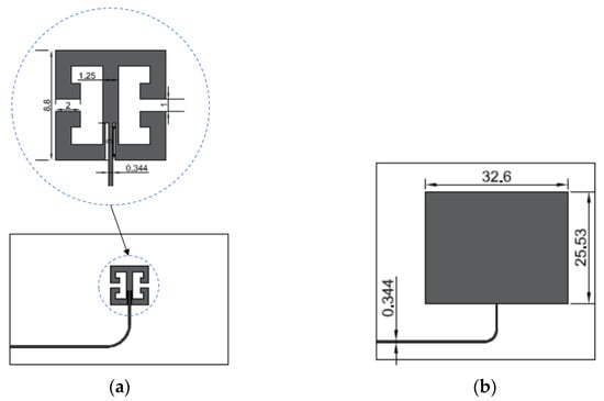
Figure 1.
Sensor design (a) Double split-ring resonator (dSRR) microstrip sensor; (b) Rectangular microstrip sensor (dimensions in mm).
The transducer is glued to the element under test (planar sample). As a result of the action of external mechanical forces on the sample, the deformation is transferred through the adhesive connection to the evaluated sensor. The flexibility of utilized FR4 laminate is enough for measured strains—in performed experiments within previous works, the evaluation was done even for plastic deformations of samples (which is far too much in the case of standard SHM applications). The resonant frequency shift is due to deformation-induced changes in the geometry of the resonator. It depends on the direction of deformation: geometric dimensions parallel to the axis of the acting force increase, while perpendicular dimensions decrease. This causes a change in the distribution of electromagnetic fields and the flow of currents, which is reflected in slight changes in the equivalent circuit of such a system as well, as in the frequency response of the sensor’s reflection coefficient and consequently the resonant frequency. Current loops dimension changes influence the inductance of the element, while electric field gap (between conductors) changes influence the capacitance of the resonator element. Thus, the principle of operation does not differ in any way from the principle of operation of commonly used microstrip resonators.
3. Sensors Validation
Numerical analysis and experimental validation were conducted for the designed sensors. The description will be presented in this section.
3.1. Numerical Analysis
The Finite Element Method (FEM) model was developed in the Comsol Multiphysics environment to evaluate the designed sensors. The numerical model geometry is shown in Figure 2. The designed microstrip sensor was fixed to the S355J2+N construction steel planar sample. This material is often utilized in civil constructions. The dimensions of the samples utilized were length 250 mm, width 45 mm, and thickness 1 mm. At first, the Solid Mechanics module was used to compute the deformation of the steel sample. In this case, the following equation was solved using FEM [31]:
where: S—second Piola-Kirchhoff stress tensor, Fv—force per unit volume.
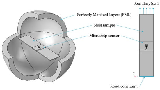
Figure 2.
Finite Element Method model with a dSRR sensor attached to the steel sample.
Mechanical loading of the sample simultaneously deforms the tested microstrip sensor. It causes the change of the current density distribution in the microstrip patch as well as the S11 frequency domain response. The electromagnetic problem was computed using the RF module, where the following equation was solved [32]:
where: σ—electric conductivity, εr—relative permittivity, µr—relative permeability, k0—wave number, E—electric field, ω—angular frequency.
The sensors’ resonant frequency was determined based on the estimation of the local minimum of the obtained magnitude of the reflection coefficient S11 characteristics. Received S11 frequency responses obtained using calculations and measurements are shown in Figure 3.
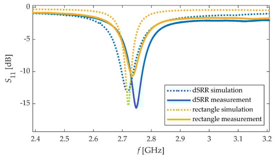
Figure 3.
Calculated and measured module of reflection coefficient S11 for considered sensors.
3.2. Experimental Validation
In this section, experimental evaluation of designed and simulated sensors was conducted. In this case, dSRR and rectangular sensors were manufactured using the photolithographic process. Dimensions of designed sensors are shown in Figure 1. Tested sensors were fixed with cyanoacrylate adhesive to the construction steel samples. This adhesive connection allowed the transmission of sample strain to sensors. The sample was extended by a custom mechanical deformation system. Next, Rohde & Schwarz ZVB20 Vector Network Analyzer (Columbia, MD, USA) was used for S11 acquisition (in the case of the deformed sensor). Measurements were carried out in the 2.3–3.3 GHz frequency range with 0.1 MHz steps. The utilized power level was 0 dBm. The photo of the measurement setup used for this purpose is shown in Figure 4. Until recently, Vector Network Analyzers were devices with large dimensions and high prices. In recent years, small and low-cost VNAs have been developed, which could be used in the future in practical SHM measurements. In our research, we used a frequency range (<3 GHz) that allowed the use of such low-cost VNAs.
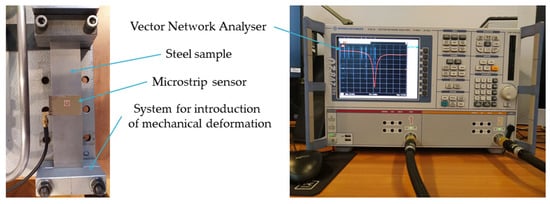
Figure 4.
Photo of the measuring system.
3.3. Results
The deformation assessment is performed by monitoring the frequency response of the reflection coefficient S11 magnitude. In order to determine the deformation, it is necessary to determine the shift of the resonance frequency Δfr from the initial state.
where: frload is the resonant frequency for the case with external mechanical load, and frε=0 is the resonant frequency without mechanical deformation.
The resonant frequency is the frequency at which the local minimum of the magnitude of S11 occurs. In order to determine the resonance frequency of the transducer, in the first step, the frequency range with the local minimum of the reflection coefficient magnitude was selected. Then a two-term Gaussian model was used to fit the measured data to the mathematical equation, and based on that, the resonant frequency was designated. The resonant frequency shifts were determined using the numerical method and measurement for the dSRR microstrip sensor and the rectangular patch. The relationships between material strain and the obtained resonant frequency shifts for the strain along the main patch axis are shown in Figure 5. Comparing the results shown in Figure 3 and Figure 5, a good convergence between simulations results and measurement was obtained. The sensitivity of the dSRR patch is lower than the rectangular microstrip sensor by 28% in simulations and 35% in measurement. The utilization of the dSRR patch made it possible to reduce the patch size by 93% (Table 1). The lower sensitivity of the dSRR sensor results from the current density distribution at a studied resonance. In the case of the rectangular patch, the current direction is parallel to the current density distribution at the first resonance. In the case of the dSRR patch, the current distribution is more multidirectional as shown in Figure 6. Moreover, the strain directional characteristics of the tested sensors were determined, as shown in Figure 7. The force direction strongly influences the change of the studied resonance frequencies. Therefore, a single resonance measurement of the deformation with these sensors can only be performed for a known strain direction.
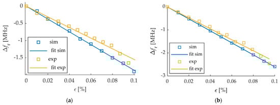
Figure 5.
Influence of strain ε on shifts of resonant frequency Δfr (a) dSRR microstrip sensor; (b) Rectangular microstrip sensor.

Table 1.
Comparison of the studied sensors.
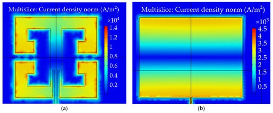
Figure 6.
Current density [A/m2] distribution in case of resonant frequency (a) dSRR microstrip sensor; (b) rectangular microstrip sensor.
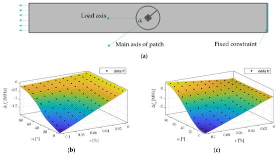
Figure 7.
Directional characteristics of Δfr for different strain levels (a) top view of the considered sample and definition of applied strain direction angle α; (b) dSRR microstrip sensor; (c) rectangular microstrip sensor.
In the case of rectangular sensor and direction angle α = 0°, increasing the strain causes a rapid decrease of Δfr, but for the direction angle α = 90°, the Δfr is slightly increasing. This is caused by an elongation of the sample in the direction parallel to the load, and its shortening in the perpendicular direction. This has an important implication: there is some direction, for which there will be no change of Δfr caused by strain, thus the sensor will be not sensitive to the strain. This restricts the application of the rectangular sensor to applications where the direction of external load is unknown. In the case of the proposed sensor, for both directions (α = 0° and α = 90°), an increase of strain causes a decrease of Δfr. Thus, there will be no such case where the proposed sensor is not sensitive to any strain.
4. Conclusions
In this article, the dSRR microstrip strain sensor has been designed and tested. The proposed sensor has been compared with a rectangular microstrip sensor. Both are designed for the same resonant frequency. This assumption eliminates the influence of the resonant frequency on the sensitivity of the transducer. So only the patch shape effect is investigated. The sensors were verified by numerical and experimental analysis. The proposed geometry allowed for the reduction of the patch size by over 90% with a simultaneous approx. There was a 30% decrease in sensitivity in relation to the rectangular resonator. This is a better result than that obtained in [17], where a 75% reduction in the patch size was achieved with a two-fold decrease in sensitivity in relation to the rectangular resonator. Table 2 shows a comparison of the sensitivity of different microstrip transducers. As can be seen, the resonant frequency, as well as the shape of the resonator, affect the sensitivity of the sensor. For similar operating frequencies (2.4–3.0 GHz—the band covered by low-cost VNAs) the dSRR sensor proposed in this paper has the best sensitivity to patch size ratio.
Table 2.
Comparison of recently reported microstrip strain sensors.
However, it is still a worse method of miniaturization of microstrip stress sensors than the utilization of laminate with high electric permittivity. The proposed method of miniaturization can be used in conjunction with a laminate with high electric permittivity, in applications where the sensitivity requirements are lower and where deformation tests on a small area are required. Moreover, the proposed sensor is devoid of one of the drawbacks of the rectangular sensor—the sensitivity does not drop to zero at the selected load direction. The obtained results are promising and allow us to state that strain sensors built on single structural elements of metamaterials or their small collections have great potential. Further work will consist of further miniaturization of the transducers and increasing their sensitivity. In the future, we also plan to focus on wireless strain sensors or sensor pairs. For this reason, the research will be extended to include the transmission coefficient and group delay. Additionally, an analysis based on 3D Smith charts [33,34] is planned.
Author Contributions
Conceptualization, M.H.; methodology, M.H.; validation, P.L.; formal analysis, M.H. and P.L.; investigation, M.H. and P.L.; data analysis, M.H.; writing—original draft preparation, M.H.; writing—review and editing, P.L.; visualization, M.H.; project administration, P.L.; funding acquisition, P.L. All authors have read and agreed to the published version of the manuscript.
Funding
This research was funded by the National Science Center, Poland (Narodowe Centrum Nauki, NCN), within the research project “Investigation of the impact of irregularities and deformations of the metasurface structure on their reflection properties for electromagnetic waves in the microwave and terahertz frequency band”, grant number 2018/02/X/ST7/02459. The APC was funded by the Research Fund of the Faculty of Electrical Engineering (West Pomeranian University of Technology, Szczecin, Poland).
Institutional Review Board Statement
Not applicable.
Informed Consent Statement
Not applicable.
Data Availability Statement
Not applicable.
Conflicts of Interest
The authors declare no conflict of interest.
References
- Alokita, S.; Rahul, V.; Jayakrishna, K.; Kar, V.R.; Rajesh, M.; Thirumalini, S.; Manikandan, M. Recent Advances and Trends in Structural Health Monitoring. Structural Health Monitoring of Biocomposites, Fibre-Reinforced Composites and Hybrid Composites; Woodhead Publishing: Sawston, UK, 2019; pp. 53–73. [Google Scholar]
- Ni, Y.Q.; Wong, K.Y. Integrating Bridge Structural Health Monitoring and Condition-Based Maintenance Management. In Proceedings of the 4th International Workshop on Civil Structural, Berlin, Germany, 6–8 November 2012. [Google Scholar]
- Maciusowicz, M.; Psuj, G. Use of Time-Dependent Multispectral Representation of Magnetic Barkhausen Noise Signals for the Needs of Non-Destructive Evaluation of Steel Materials. Sensors 2019, 19, 1443. [Google Scholar] [CrossRef] [Green Version]
- Surhone, L.M. Strain Gauge: Edward E. Simmons, Arthur Claude Ruge, Cyanoacrylate, Electrical Resistance, Wheatstone Bridge, Electrical Conductance, Electrical Conductivity; Betascript Publishing: Beau Bassin, Mauritius, 2010; ISBN 10-613033124X. [Google Scholar]
- Sun, Y.; Thompson, S.E.; Nishida, T. Strain Effect in Semiconductors, Theory and Device Applications; Springer: New York, NY, USA, 2010; ISBN 978-1-4419-0552-9. [Google Scholar]
- Islam, M.N.; Seethaler, R.; Alam, M.S. Characterization of piezoelectric materials for simultaneous strain and temperature sensing for ultra-low frequency applications. Smart Mater. Struct. 2015, 24, 085019. [Google Scholar] [CrossRef]
- Yang, J.; Hou, P.; Yang, C.; Yang, N. Study of a Long-Gauge FBG Strain Sensor with Enhanced Sensitivity and Its Application in Structural Monitoring. Sensors 2021, 21, 3492. [Google Scholar] [CrossRef] [PubMed]
- Tata, U.; Huang, H.; Carter, R.L.; Chiao, J.C. Exploiting a patch antenna for strain measurements. Meas. Sci. Technol. 2008, 20, 015201. [Google Scholar] [CrossRef]
- Wang, W.; Ge, H.; Liu, T.; Liu, M. Study of Patch Antennas for Strain Measurement. Electromagn. Nondestruct. Eval. (XVIII) 2015, 40, 313–321. [Google Scholar]
- Sharama, N.; Thakare, V.V. Analysis of microstrip rectangular patch antenna as a strain sensor. Int. J. Res. Electron. Commun. Technol. 2015, 2, 17–19. [Google Scholar]
- Benchirouf, A.; Zichner, R.; Muller, C.; Kanoun, O. Electromagnetic simulation of flexible strain sensor based microstrip patch antenna. Int. J. Microw. Opt. Technol. 2015, 10, 397–401. [Google Scholar]
- Lopato, P.; Herbko, M. Microwave structural health monitoring sensor for deformation measurement of bended steel structures: Influence of curvature effect. Radioengineering 2017, 26, 1060–1066. [Google Scholar] [CrossRef]
- Lopato, P.; Herbko, M. A Circular Microstrip Antenna Sensor for Direction Sensitive Strain Evaluation. Sensors 2018, 18, 310. [Google Scholar] [CrossRef] [PubMed] [Green Version]
- Daliri, A.; Galehdar, A.; Rowe, W.S.; Ghorbani, K.; John, S. Utilising microstrip patch antenna strain sensors for structural health monitoring. J. Intell. Mater. Syst. Struct. 2011, 23, 169–182. [Google Scholar] [CrossRef]
- Daliri, A.; Galehdar, A.; Rowe, W.S.T.; John, S.; Wang, C.H.; Ghorbani, K. Quality factor effect on the wireless range of microstrip patch antenna strain sensors. Sensors 2014, 14, 595–605. [Google Scholar] [CrossRef] [PubMed] [Green Version]
- Daliri, A.; Galehdar, A.; John, S.; Rowe, W.S.T.; Ghorbani, K. Slotted Circular Microstrip Antenna Application in Strain Based Structural Health Monitoring. In Proceedings of the 14th Australian International Aerospace Congress, Melbourne, Australia, 28 February–3 March 2011. [Google Scholar]
- Herbko, M.; Lopato, P. Microstrip Patch Strain Sensor Miniaturization Using Sierpinski Curve Fractal Geometry. Sensors 2019, 19, 3989. [Google Scholar] [CrossRef] [PubMed] [Green Version]
- Ossa-Molina, O.; Duque-Giraldo, J.; Reyes-Vera, E. Strain sensor based on rectangular microstrip antenna: Numerical methodologies and experimental validation. IEEE Sens. J. 2021, 21, 22908–22917. [Google Scholar] [CrossRef]
- Hamad, A.H.; Mian, A. Radio frequency response of flexible microstrip patch antennas under compressive and bending loads using multiphysics modeling approach. Int. J. RF Microw. Comput. Aided Eng. 2019, 29, e21649. [Google Scholar] [CrossRef]
- Chung, K.L.; Wang, L.; Luo, J.; Li, Y.; Li, Y. Comparative study on directional sensitivity of patch-antenna-based strain sensors. Int. J. RF Microw. Comput. Aided Eng. 2020, 30, e22398. [Google Scholar] [CrossRef]
- Chunhee, C.; Yi, X.H.; Li, D.; Wang, Y.; Tentzeris, M.M. Passive wireless frequency doubling antenna sensor for strain and crack sensing. IEEE Sens. J. 2016, 16, 5725–5733. [Google Scholar]
- Herbko, M.; Lopato, P. Double patch sensor for identification of stress level and direction. Int. J. RF Microw. Comput. Aided Eng. 2019, 29, e21977. [Google Scholar] [CrossRef]
- Chakaravarthi, G.; Logakannan, K.P.; Philip, J.; Rengaswamy, J.; Ramachandran, V.; Arunachalam, K. Reusable Passive Wireless RFID Sensor for Strain Measurement on Metals. IEEE Sens. J. 2018, 18, 5143–5150. [Google Scholar] [CrossRef]
- Lopato, P.; Herbko, M. Analysis of rectangular microstrip strain sensor. Weld Technol. Rev. 2017, 89, 37–41. [Google Scholar]
- Herbko, M.; Lopato, P. Sensitivity Analysis of Circular Microstrip Strain Sensor. In Proceedings of the 2019 International Interdisciplinary PhD Workshop (IIPhDW), Wismar, Germany, 15–17 May 2019. [Google Scholar]
- Withayachumnankul, W.; Abbott, D. Metamaterials in the Terahertz Regime. IEEE Photonics J. 2009, 1, 99–118. [Google Scholar] [CrossRef]
- Oliveri, G.; Werner, D.H.; Massa, A. Reconfigurable electromagnetics through metamaterials—A review. Proc. IEEE 2015, 103, 1034–1056. [Google Scholar] [CrossRef] [Green Version]
- Marques, R.; Martin, F.; Sorolla, M. Metamaterials with Negative Parameters—Theory, Design, and Microwave Applications; John Wiley & Sons: Hoboken, NJ, USA, 2008. [Google Scholar]
- Lopato, P.; Herbko, M. Evaluation of Selected Metasurfaces’ Sensitivity to Planar Geometry Distortions. Appl. Sci. 2020, 10, 261. [Google Scholar] [CrossRef] [Green Version]
- Balanis, C.A. Antenna Theory: Analysis and Design, 3rd ed.; John Wiley & Sons: Hoboken, NJ, USA, 2005; pp. 811–882. ISBN 978-1-119-09493-7. [Google Scholar]
- Structural Mechanics Module User’s Guide, Comsol. Available online: https://doc.comsol.com/5.3/doc/com.comsol.help.sme/StructuralMechanicsModuleUsersGuide.pdf (accessed on 16 November 2021).
- RF Module User’s Guide, Comsol. Available online: https://doc.comsol.com/5.3/doc/com.comsol.help.rf/RFModuleUsersGuide.pdf (accessed on 16 November 2021).
- Iqbal, A.; Tiang, J.J.; Wong, S.K.; Alibakhshikenari, M.; Falcone, F.; Limiti, E. Multimode HMSIW-Based Bandpass Filter with Improved Selectivity for Fifth-Generation (5G) RF Front-Ends. Sensors 2020, 20, 7320. [Google Scholar] [CrossRef] [PubMed]
- Muller, A.A.; Sanabria-Codesal, E.; Moldoveanu, A.; Asavei, V.; Lucyszyn, S. Extended capabilities of the 3-D smith chart with group delay and resonator quality factor. IEEE Trans. Microw. Theory Tech. 2016, 65, 10–19. [Google Scholar] [CrossRef] [Green Version]
Publisher’s Note: MDPI stays neutral with regard to jurisdictional claims in published maps and institutional affiliations. |
© 2021 by the authors. Licensee MDPI, Basel, Switzerland. This article is an open access article distributed under the terms and conditions of the Creative Commons Attribution (CC BY) license (https://creativecommons.org/licenses/by/4.0/).