
Improving the Autogenous Self-Sealing of Mortar: Influence of Curing Condition

Abstract
1. Introduction
2. Materials and Methods
2.1. Materials and Samples Preparation
2.2. Self-Sealing Conditions Design
2.3. Experimental Procedures
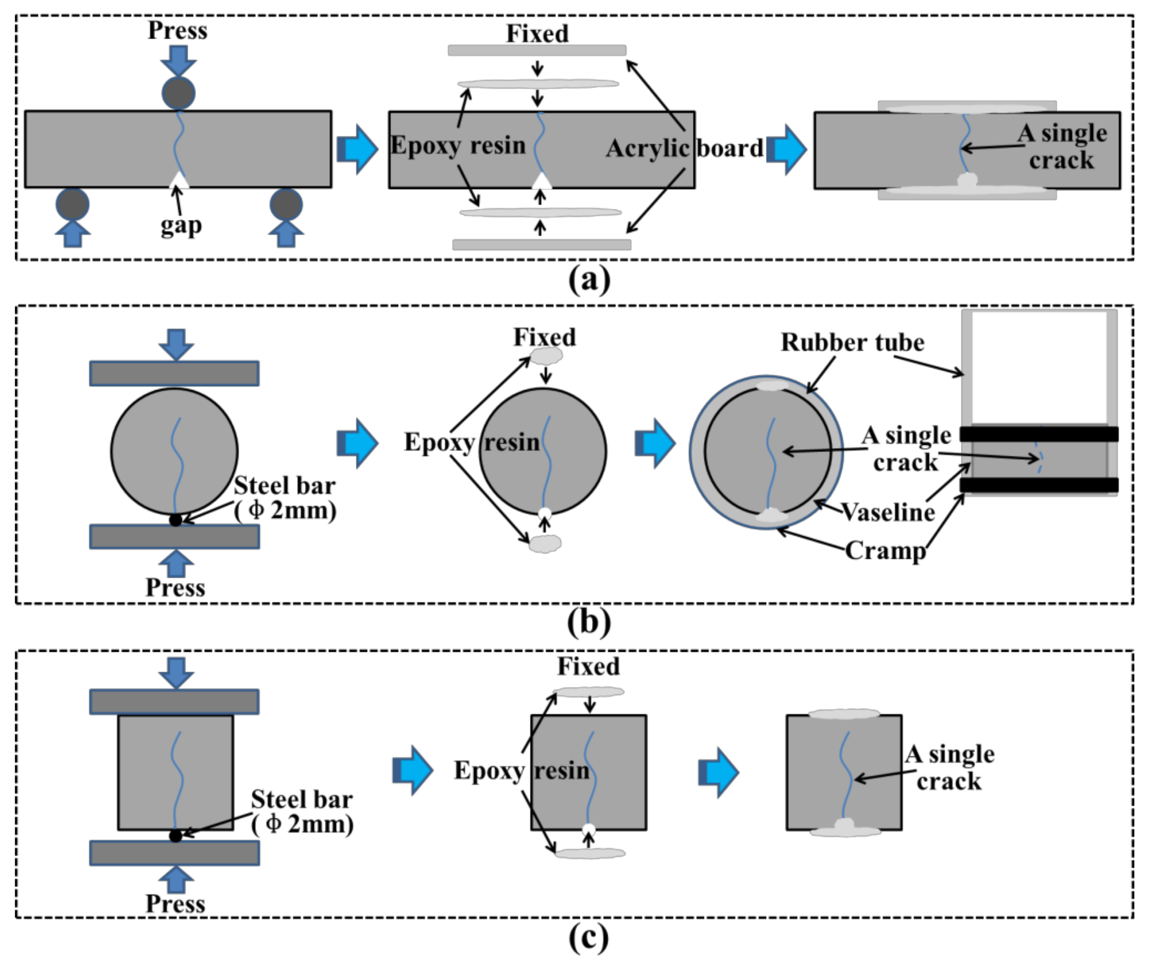
2.3.1. Preparation of a Single Crack
2.3.2. Evaluation for the Closure of Surface Cracks
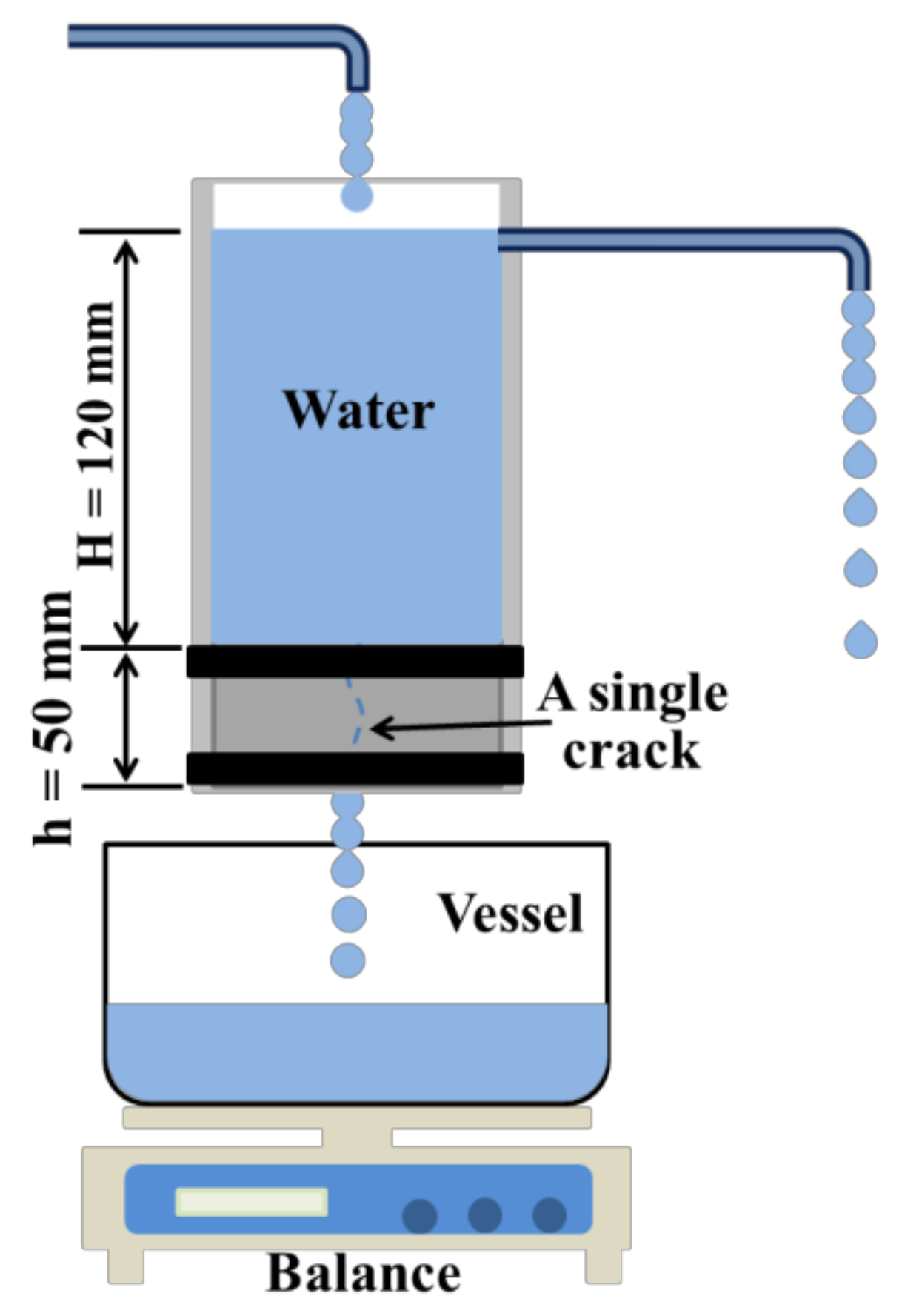
2.3.3. Water Permeability
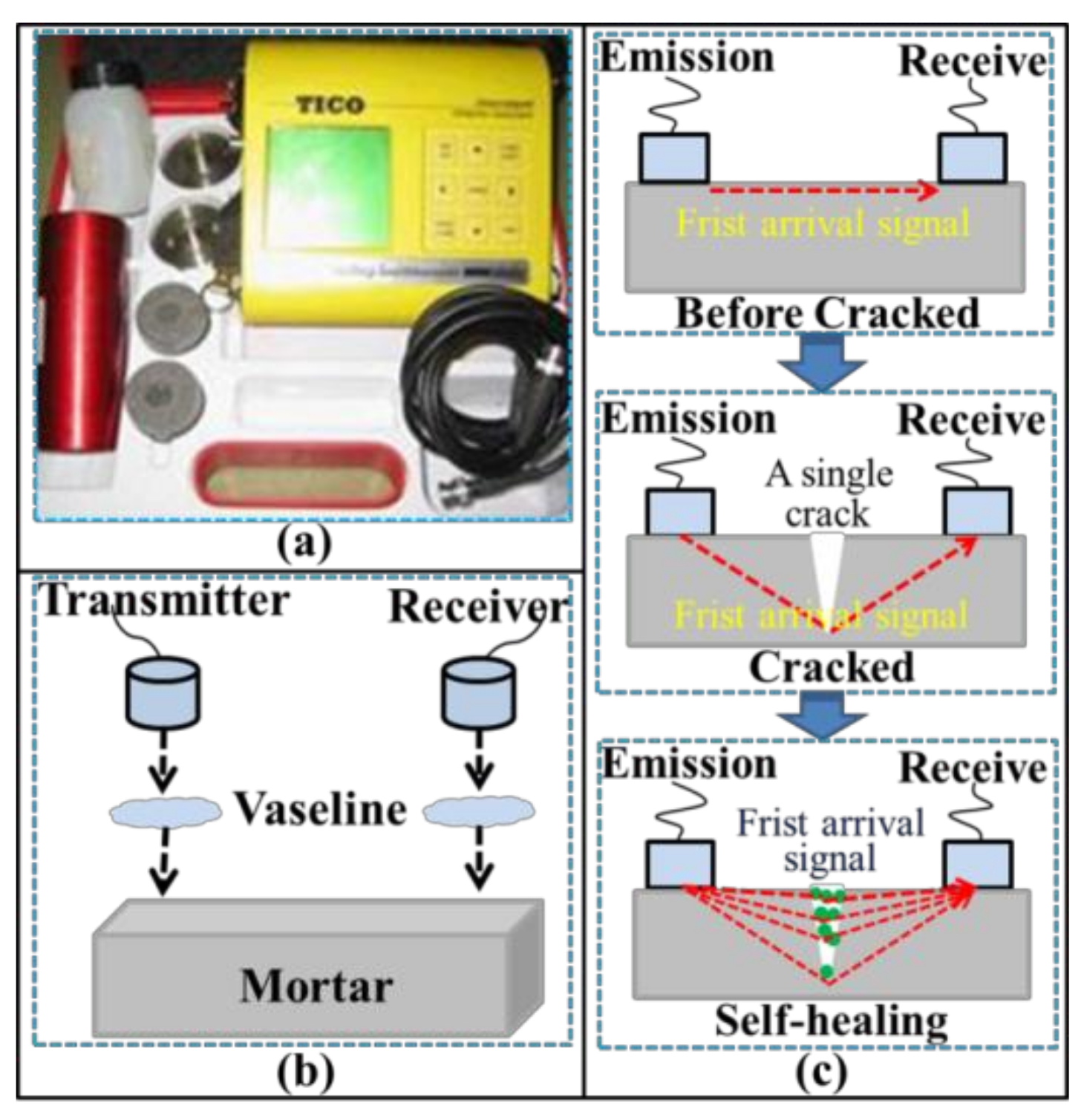
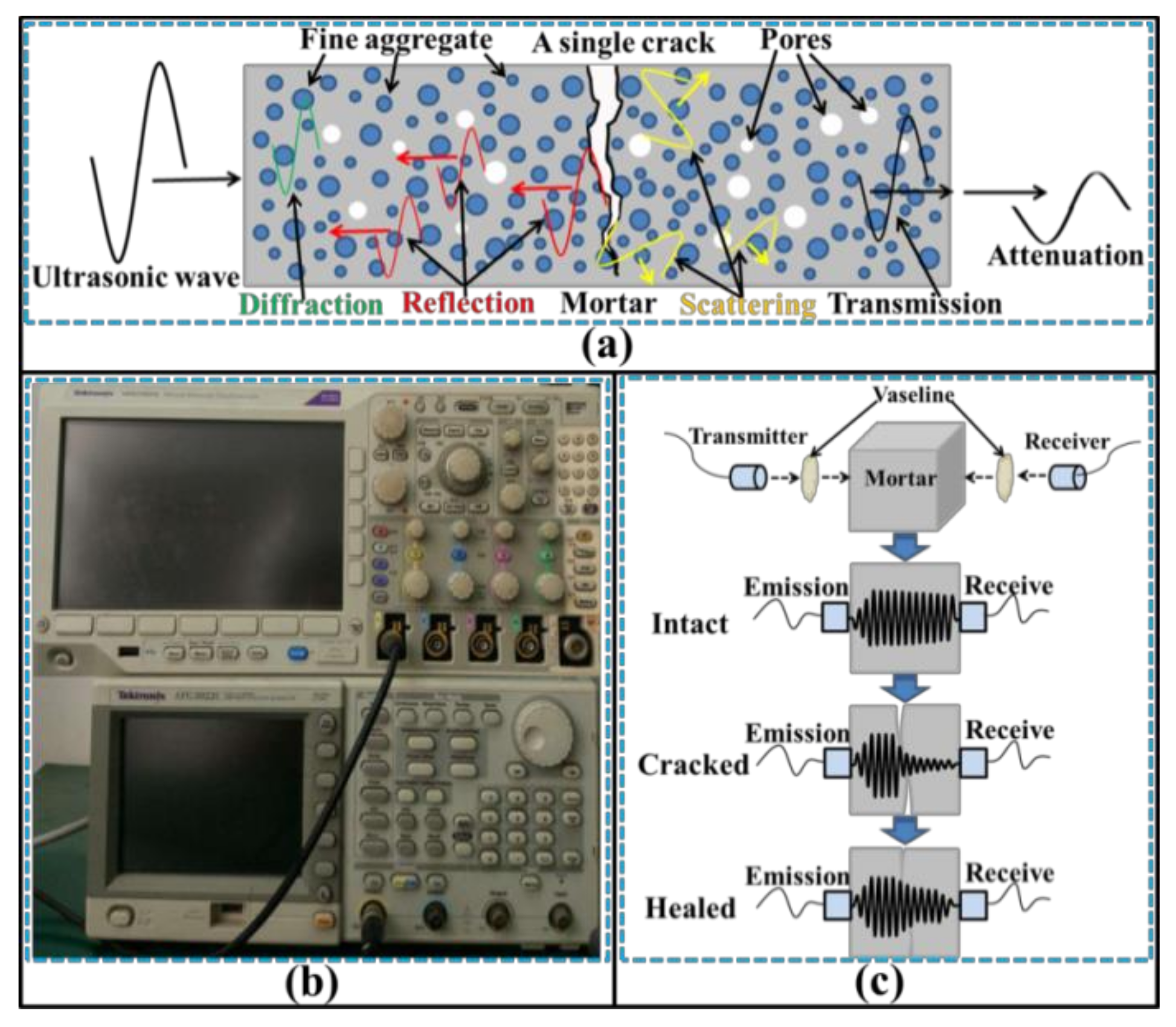
2.3.4. Ultrasonic Tests
2.3.5. Characterization of Self-Sealing Products
3. Results and Discussion
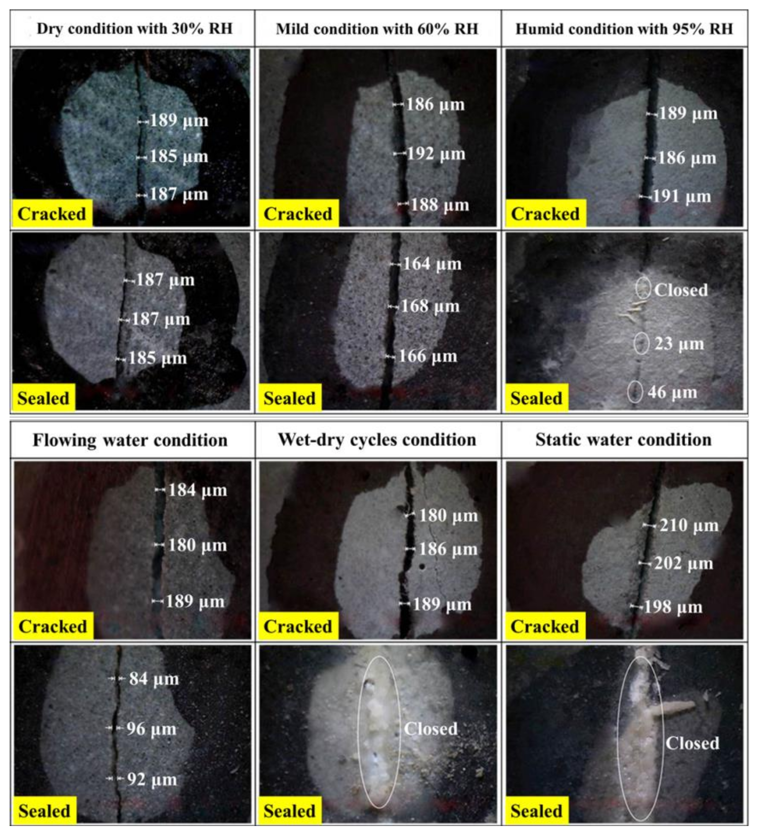
3.1. Closure of Surface Crack
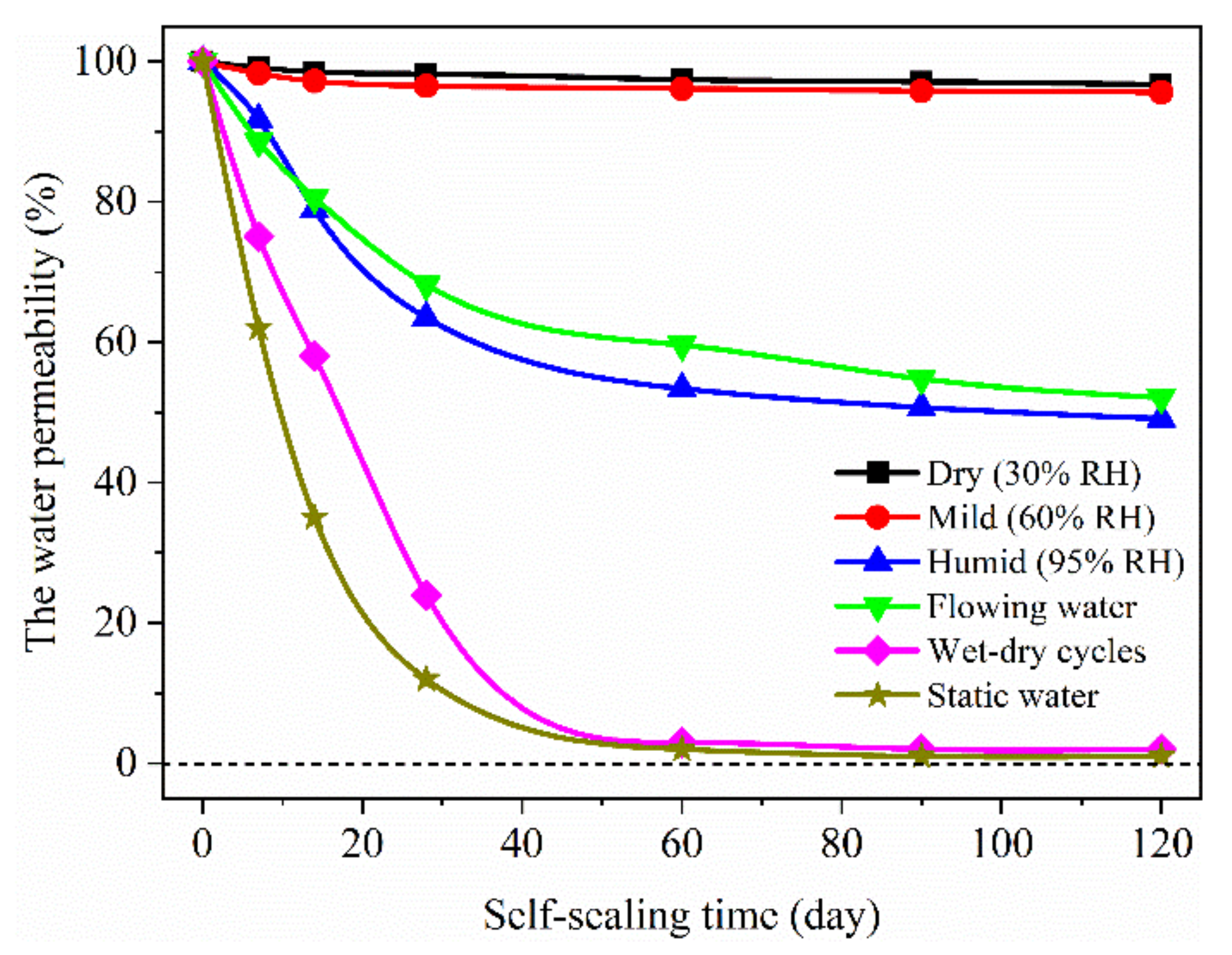
3.2. Water Permeability
3.3. Ultrasonic Tests
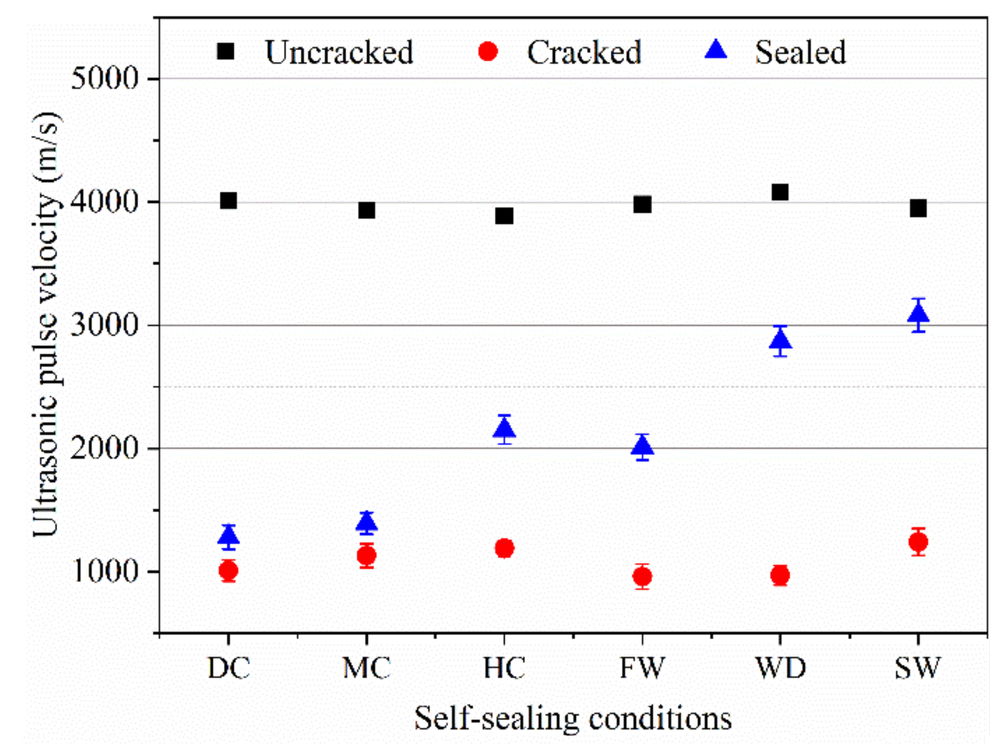
3.3.1. UPV
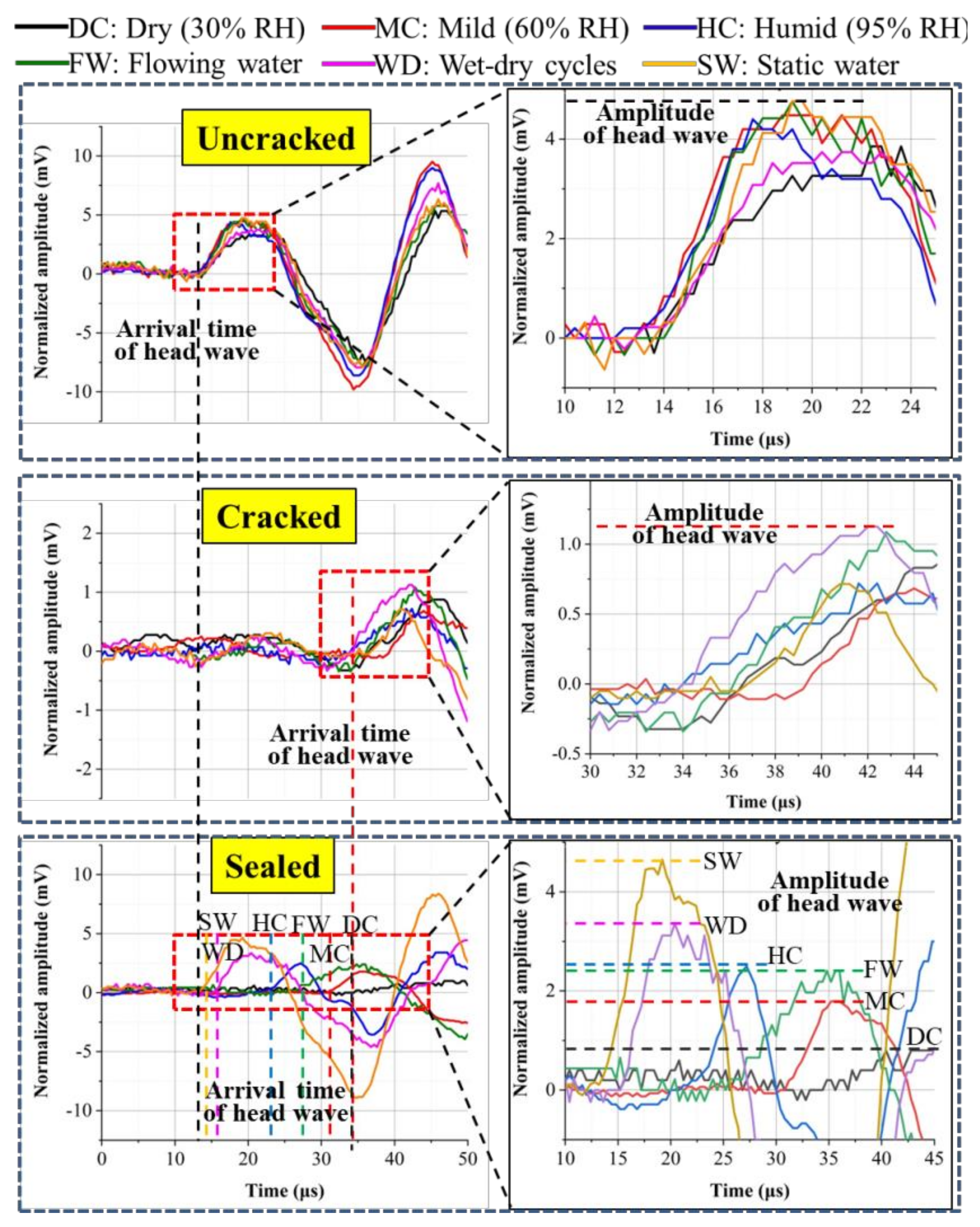
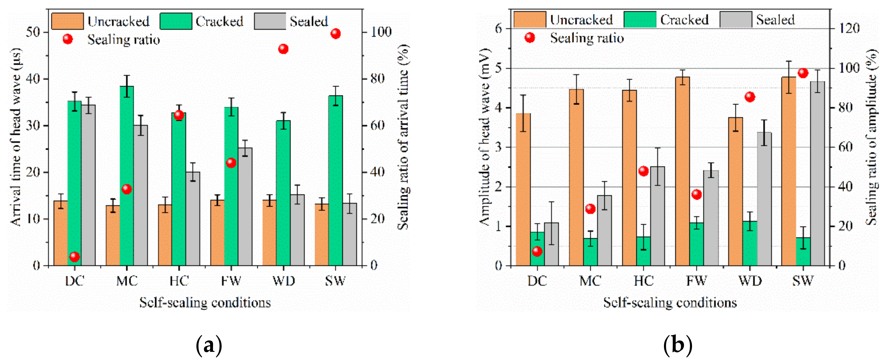
3.3.2. Head Wave of Ultrasound
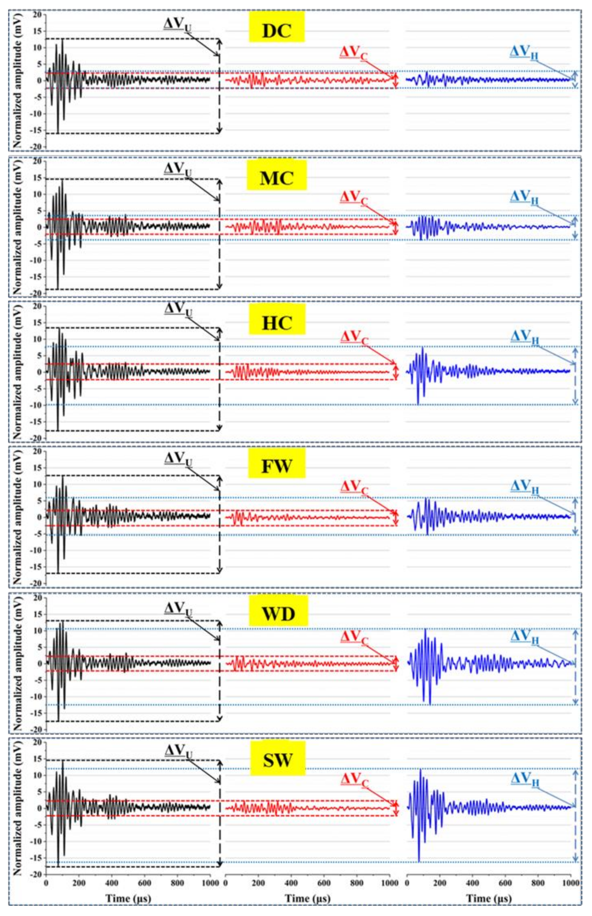
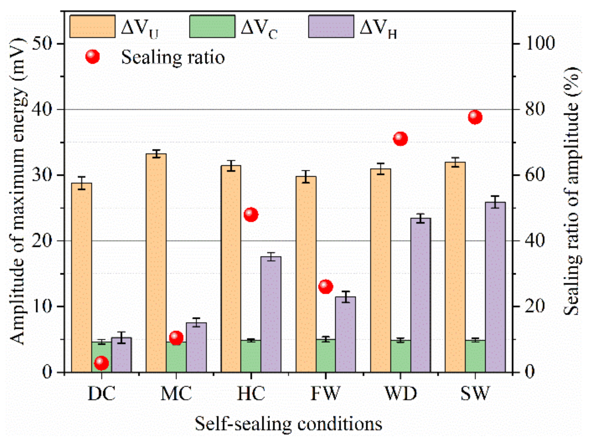
3.3.3. Ultrasonic Waveform
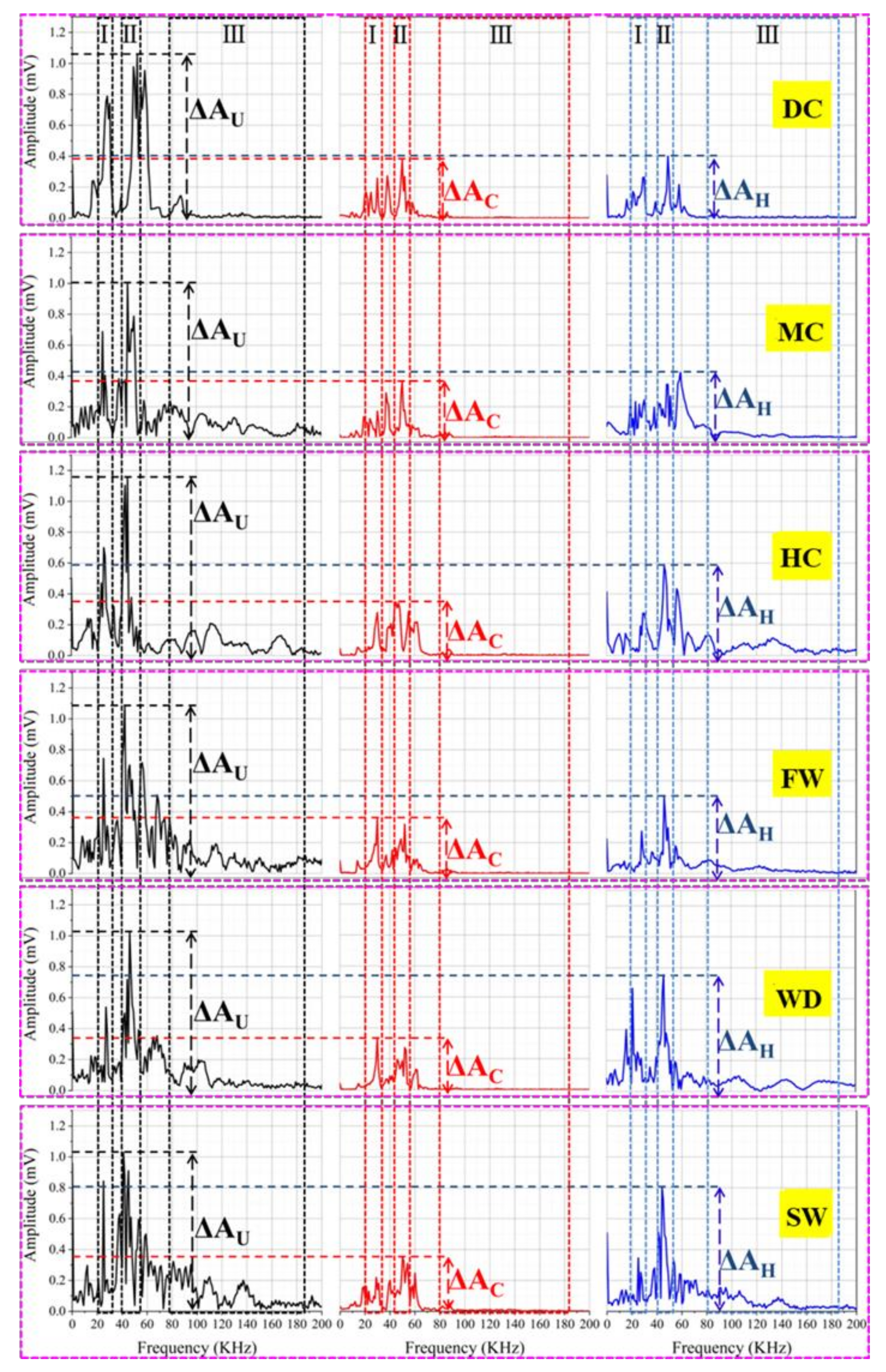
3.3.4. Frequency Analysis of Ultrasonic Wave
3.4. Characterization of Self-Sealing Products
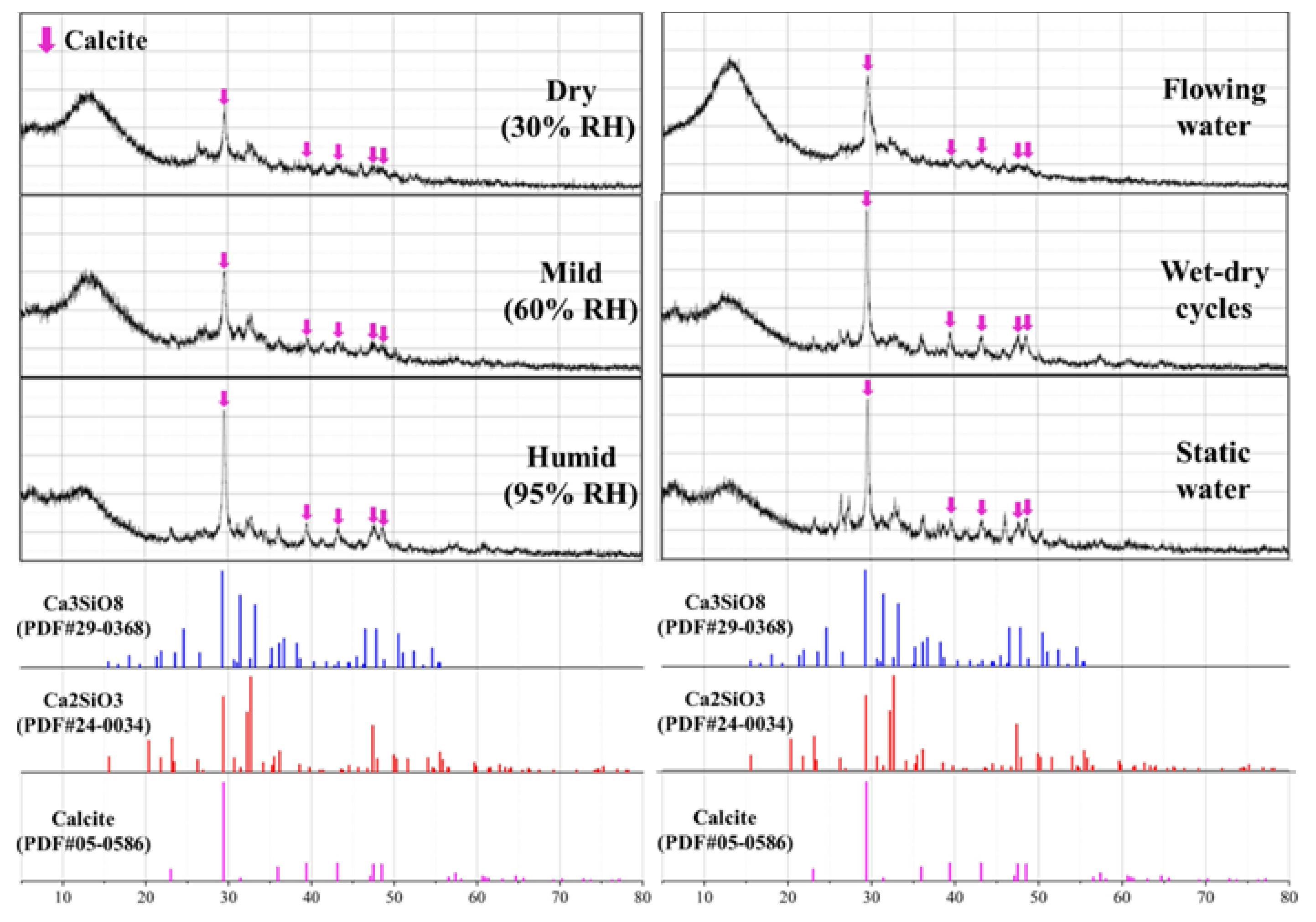
3.4.1. XRD Analysis
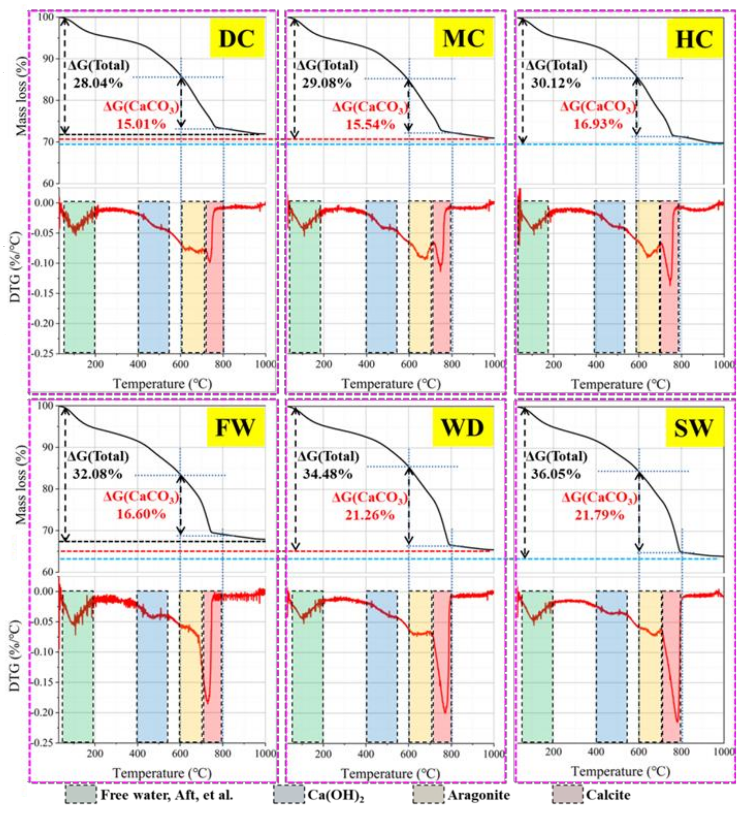
3.4.2. TG Analysis
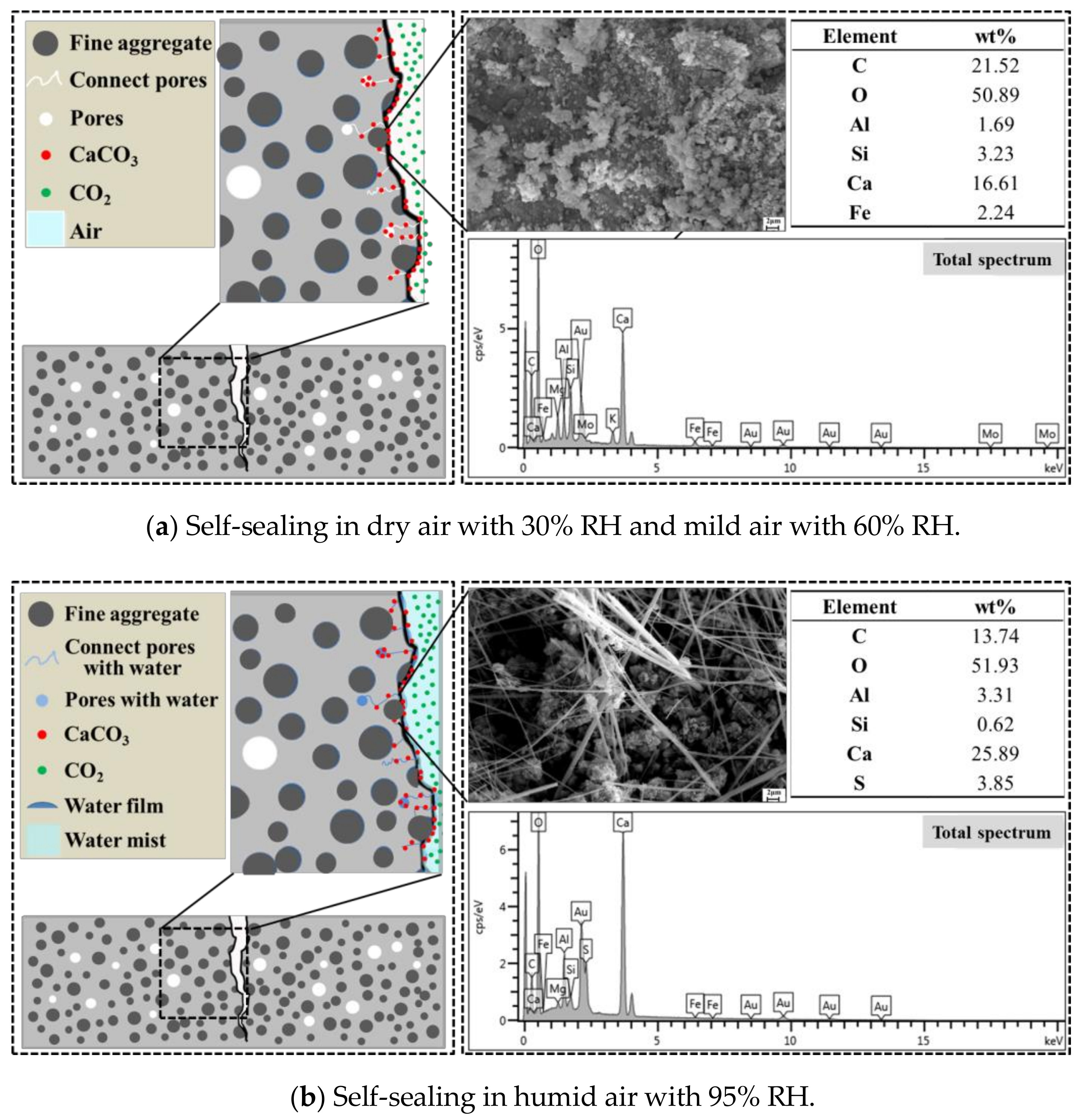
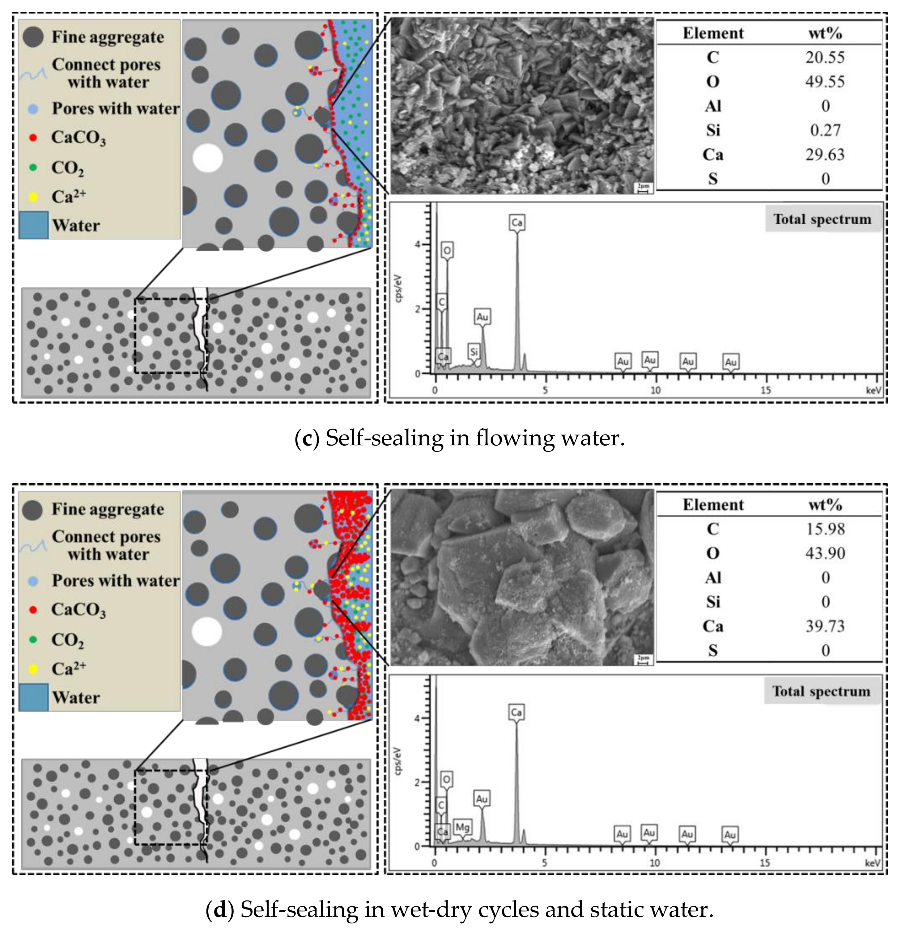
3.5. Mechanism Analysis of Autogenous Self-Sealing
4. Conclusions
- (1)
- The self-sealing of concrete cracks includes the surface cracks sealing and the internal cracks sealing. The research shows that the crack width observation and the water permeability test are suitable for the evaluation of self-sealing for surface cracks and the ultrasonic tests can characterize the self-sealing of internal cracks.
- (2)
- Water promotes the self-sealing of surface cracks. The surface cracks of samples cured in static water and wet-dry cycles are closed and the water permeability of these samples is close to zero. With the increase of relative humidity, the crack width and the water permeability decrease.
- (3)
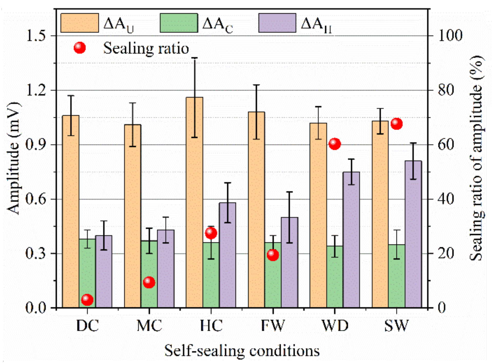
- Water contributes to the self-sealing of internal cracks. The self-sealing ratios based on the ultrasonic test for the samples cured in static water and wet-dry cycles are greater than 60%, which are higher than the samples cured in other conditions. Similarly, the self-sealing ratios also improve with the increase of relative humidity.
- (4)
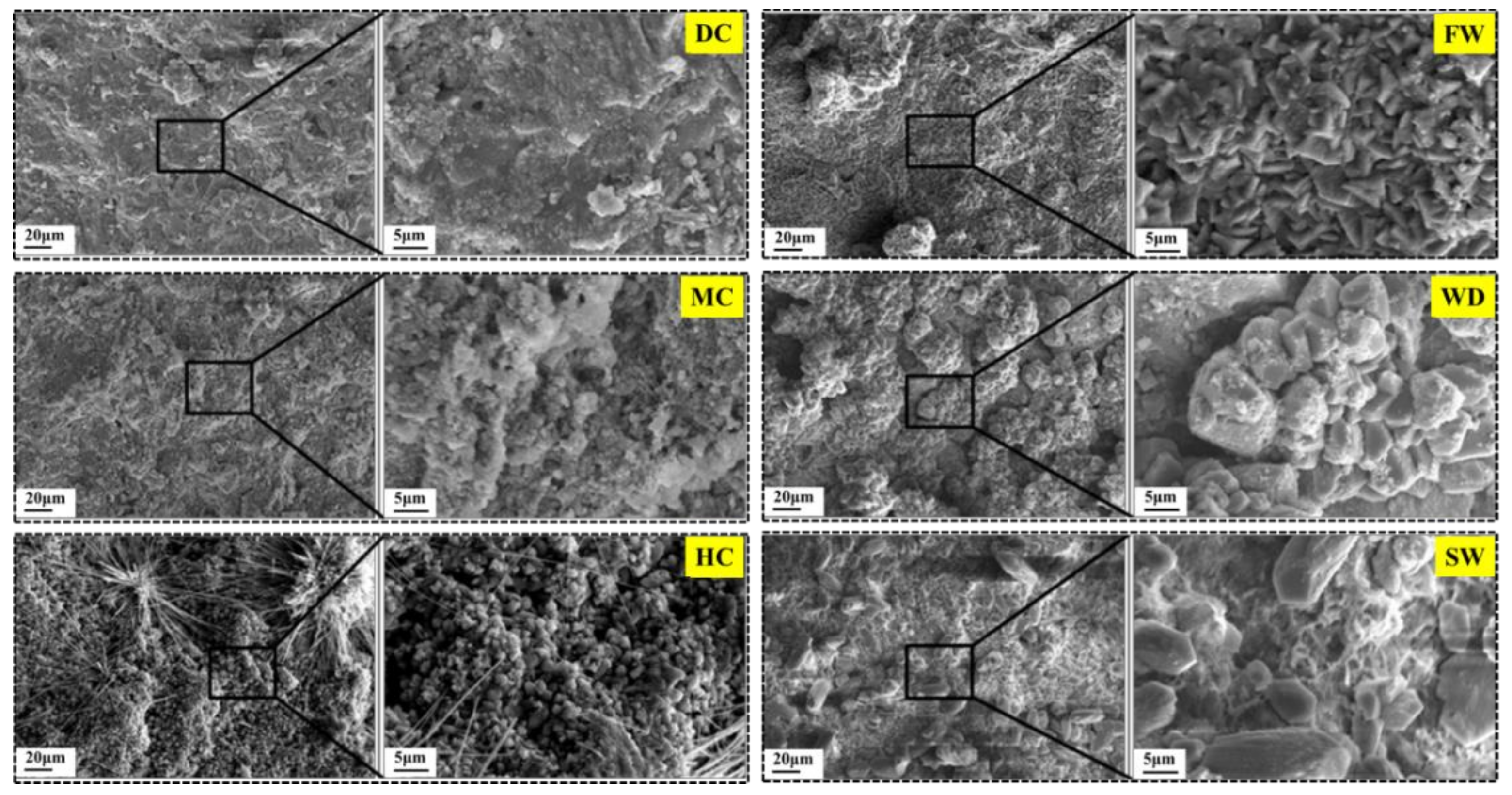
- The static water promotes the self-sealing of concrete cracks, because of the acceleration of the continued hydration of unhydrated cement particles and the precipitation of CaCO3. The flowing water takes away the Ca2+ from the dissolution of the unhydrated cement particles and the hydration products, which hinders the precipitation of CaCO3 and thereby negatively affects the self-sealing of the cracks.
Author Contributions
Funding
Institutional Review Board Statement
Informed Consent Statement
Data Availability Statement
Acknowledgments
Conflicts of Interest
References
- Roig-Flores, M.; Pirritano, F.; Serna, P.; Ferrara, L. Effect of crystalline admixtures on the self-healing capability of early-age concrete studied by means of permeability and crack closing tests. Constr. Build. Mater. 2016, 114, 447–457. [Google Scholar] [CrossRef]
- Feiteira, J.; Gruyaert, E.; De Belie, N. Self-healing of moving cracks in concrete by means of encapsulated polymer precursors. Constr. Build. Mater. 2016, 102, 671–678. [Google Scholar] [CrossRef]
- Jonkers, H.M.; Thijssen, A.; Muyzer, G.; Copuroglu, O.; Schlangen, E. Application of bacteria as self-healing agent for the development of sustainable concrete. Ecol. Eng. 2010, 36, 230–235. [Google Scholar] [CrossRef]
- Wang, X.; Zhang, J.; Han, R.; Han, N.; Xing, F. Evaluation of damage and repair rate of self-healing microcapsule-based cementitious materials using electrochemical impedance spectroscopy. J. Clean. Prod. 2019, 235, 966–976. [Google Scholar] [CrossRef]
- Snoeck, D.; De Belie, N. Repeated Autogenous Healing in Strain-Hardening Cementitious Composites by Using Superabsorbent Polymers. J. Mater. Civ. Eng. 2016, 28, 04015086. [Google Scholar] [CrossRef]
- Van Tittelboom, K.; Gruyaert, E.; Rahier, H.; De Belie, N. Influence of mix composition on the extent of autogenous crack healing by continued hydration or calcium carbonate formation. Constr. Build. Mater. 2012, 37, 349–359. [Google Scholar] [CrossRef]
- Rahmani, H.; Bazrgar, H. Effect of coarse cement particles on the self-healing of dense concretes. Mag. Concr. Res. 2015, 67, 476–486. [Google Scholar] [CrossRef]
- Yuan, L.; Chen, S.; Wang, S.; Huang, Y.; Yang, Q.; Liu, S.; Wang, J.; Du, P.; Cheng, X.; Zhou, Z. Research on the Improvement of Concrete Autogenous Self-healing Based on the Regulation of Cement Particle Size Distribution (PSD). Materials 2019, 12, 2818. [Google Scholar] [CrossRef]
- Qiu, J.; Tan, H.S.; Yang, E.-H. Coupled effects of crack width, slag content, and conditioning alkalinity on autogenous healing of engineered cementitious composites. Cem. Concr. Compos. 2016, 73, 203–212. [Google Scholar] [CrossRef]
- Huang, H.; Ye, G.; Damidot, D. Effect of blast furnace slag on self-healing of microcracks in cementitious materials. Cem. Concr. Res. 2014, 60, 68–82. [Google Scholar] [CrossRef]
- Huang, H.; Ye, G.; Qian, C.; Schlangen, E. Self-healing in cementitious materials: Materials, methods and service conditions. Mater. Des. 2016, 92, 499–511. [Google Scholar] [CrossRef]
- Roig-Flores, M.; Moscato, S.; Serna, P.; Ferrara, L. Self-healing capability of concrete with crystalline admixtures in different environments. Constr. Build. Mater. 2015, 86, 1–11. [Google Scholar] [CrossRef]
- Luo, M.; Qian, C.-X.; Li, R.-Y. Factors affecting crack repairing capacity of bacteria-based self-healing concrete. Constr. Build. Mater. 2015, 87, 1–7. [Google Scholar] [CrossRef]
- Wang, J.; Liu, M.; Wang, Y.; Zhou, Z.; Xu, D.; Du, P.; Cheng, X. Synergistic effects of nano-silica and fly ash on properties of cement-based composites. Constr. Build. Mater. 2020, 262, 120737. [Google Scholar] [CrossRef]
- Wang, Y.; Xu, Z.; Wang, J.; Zhou, Z.; Du, P.; Cheng, X. Synergistic effect of nano-silica and silica fume on hydration properties of cement-based materials. J. Therm. Anal. Calorim. 2020, 140, 2225–2235. [Google Scholar] [CrossRef]
- Wang, R.; Yu, J.; Gu, S.; He, P.; Han, X.; Liu, Q. Investigation of self-healing capability on surface and internal cracks of cement mortar with ion chelator. Constr. Build. Mater. 2020, 236, 117598. [Google Scholar] [CrossRef]
- Ahn, E.; Kim, H.; Sim, S.-H.; Shin, S.W.; Shin, M. Principles and Applications of Ultrasonic-Based Nondestructive Methods for Self-Healing in Cementitious Materials. Materials 2017, 10, 278. [Google Scholar] [CrossRef]
- Ferrara, L.; Van Mullem, T.; Alonso, M.C.; Antonaci, P.; Borg, R.P.; Cuenca, E.; Jefferson, A.; Ng, P.-L.; Peled, A.; Roig-Flores, M.; et al. Experimental characterization of the self-healing capacity of cement based materials and its effects on the material performance: A state of the art report by COST Action SARCOS WG2. Constr. Build. Mater. 2018, 167, 115–142. [Google Scholar] [CrossRef]
- Wang, X.; Yang, Z.; Fang, C.; Han, N.; Zhu, G.; Tang, J.; Xing, F. Evaluation of the mechanical performance recovery of self-healing cementitious materials—its methods and future development: A review. Constr. Build. Mater. 2019, 212, 400–421. [Google Scholar] [CrossRef]
- Xu, J.; Yao, W. Multiscale mechanical quantification of self-healing concrete incorporating non-ureolytic bacteria-based healing agent. Cem. Concr. Res. 2014, 64, 1–10. [Google Scholar] [CrossRef]
- Pang, B.; Zhou, Z.; Hou, P.; Du, P.; Zhang, L.; Xu, H. Autogenous and engineered healing mechanisms of carbonated steel slag aggregate in concrete. Constr. Build. Mater. 2016, 107, 191–202. [Google Scholar] [CrossRef]
- Suaris, W.; Fernando, V. Detection of crack growth in concrete from ultrasonic intensity measurements. Mater. Struct. 1987, 20, 214–220. [Google Scholar] [CrossRef]
- Kantiranis, N.; Tsirambides, A.; Filippidis, A.; Christaras, B. Technological characteristics of the calcined limestone from Agios Panteleimonas, Macedonia, Greece. Mater. Struct. 1999, 32, 546–551. [Google Scholar] [CrossRef]
- Dongyu, X.; Shifeng, H.; Lei, Q.; Lingchao, L.; Xin, C. Monitoring of cement hydration reaction process based on ultrasonic technique of piezoelectric composite transducer. Constr. Build. Mater. 2012, 35, 220–226. [Google Scholar] [CrossRef]
- Cerrillo, C.; Jiménez, A.; Rufo, M.; Paniagua, J.; Pachón, F. New contributions to granite characterization by ultrasonic testing. Ultrasonics 2014, 54, 156–167. [Google Scholar] [CrossRef]
- Punurai, W.; Jarzynski, J.; Qu, J.; Kurtis, K.; Jacobs, L. Characterization of dissipation losses in cement paste with diffuse ultrasound. Mech. Res. Commun. 2007, 34, 289–294. [Google Scholar] [CrossRef]
- Ducasse-Lapeyrusse, J.; Gagné, R.; Lors, C.; Damidot, D. Effect of calcium gluconate, calcium lactate, and urea on the kinetics of self-healing in mortars. Constr. Build. Mater. 2017, 157, 489–497. [Google Scholar] [CrossRef]
- Sidiq, A.; Gravina, R.; Giustozzi, F. Is concrete healing really efficient? A review. Constr. Build. Mater. 2019, 205, 257–273. [Google Scholar] [CrossRef]
- Chindasiriphan, P.; Yokota, H.; Pimpakan, P. Effect of fly ash and superabsorbent polymer on concrete self-healing ability. Constr. Build. Mater. 2020, 233, 116975. [Google Scholar] [CrossRef]
- Wu, M.; Johannesson, B.; Geiker, M. A review: Self-healing in cementitious materials and engineered cementitious composite as a self-healing material. Constr. Build. Mater. 2012, 28, 571–583. [Google Scholar] [CrossRef]
- Wang, K.; Shah, S.P.; Mishulovich, A. Effects of curing temperature and NaOH addition on hydration and strength development of clinker-free CKD-fly ash binders. Cem. Concr. Res. 2004, 34, 299–309. [Google Scholar] [CrossRef]
- Kurda, R.; de Brito, J.; Silvestre, J.D. Carbonation of concrete made with high amount of fly ash and recycled concrete aggregates for utilization of CO2. J. CO2 Util. 2019, 29, 12–19. [Google Scholar] [CrossRef]
- Ferrara, L.; Krelani, V.; Carsana, M. A “fracture testing” based approach to assess crack healing of concrete with and without crystalline admixtures. Constr. Build. Mater. 2014, 68, 535–551. [Google Scholar] [CrossRef]
- Gagne, R.R.J.; Argouges, M. A study of the natural self-healing of mortars using air-flow measurements. Mater. Struct. 2012, 45, 1625–1638. [Google Scholar] [CrossRef]
- Reddy, T.C.S.; Ravitheja, A. Macro mechanical properties of self healing concrete with crystalline admixture under different environments. Ain Shams Eng. J. 2019, 10, 23–32. [Google Scholar] [CrossRef]
- Ma, H.; Qian, S.; Zhang, Z. Effect of self-healing on water permeability and mechanical property of Medium-Early-Strength Engineered Cementitious Composites. Constr. Build. Mater. 2014, 68, 92–101. [Google Scholar] [CrossRef]
- Zhang, P.; Dai, Y.; Ding, X.; Zhou, C.; Xue, X.; Zhao, T. Self-healing behaviour of multiple microcracks of strain hardening cementitious composites (SHCC). Constr. Build. Mater. 2018, 169, 705–715. [Google Scholar] [CrossRef]


| Compositions | CaO | SiO2 | Al2O3 | MgO | Fe2O3 | SO3 | Others |
|---|---|---|---|---|---|---|---|
| Content (%) | 57.82 | 22.16 | 6.36 | 2.94 | 2.78 | 4.20 | 3.74 |
| Surface Area (m2/kg) | Average Particle Size (μm) | Setting Time (min) | Compressive Strength (MPa) | ||
|---|---|---|---|---|---|
| Initial | Final | 3 d | 28 d | ||
| 346 | 18.85 | 80 | 220 | 23.4 | 48.7 |
Publisher’s Note: MDPI stays neutral with regard to jurisdictional claims in published maps and institutional affiliations. |
© 2021 by the authors. Licensee MDPI, Basel, Switzerland. This article is an open access article distributed under the terms and conditions of the Creative Commons Attribution (CC BY) license (https://creativecommons.org/licenses/by/4.0/).
Share and Cite
Yuan, L.; Li, M.; Huang, Y.; Zhou, Z.; Luan, C.; Ren, Z.; Liu, Y.; Zhou, T.; Cheng, X.; Wang, J. Improving the Autogenous Self-Sealing of Mortar: Influence of Curing Condition. Materials 2021, 14, 2068. https://doi.org/10.3390/ma14082068
Yuan L, Li M, Huang Y, Zhou Z, Luan C, Ren Z, Liu Y, Zhou T, Cheng X, Wang J. Improving the Autogenous Self-Sealing of Mortar: Influence of Curing Condition. Materials. 2021; 14(8):2068. https://doi.org/10.3390/ma14082068
Chicago/Turabian StyleYuan, Lianwang, Min Li, Yongbo Huang, Zonghui Zhou, Congqi Luan, Zunchao Ren, Yongyi Liu, Tongtong Zhou, Xin Cheng, and Jinbang Wang. 2021. "Improving the Autogenous Self-Sealing of Mortar: Influence of Curing Condition" Materials 14, no. 8: 2068. https://doi.org/10.3390/ma14082068
APA StyleYuan, L., Li, M., Huang, Y., Zhou, Z., Luan, C., Ren, Z., Liu, Y., Zhou, T., Cheng, X., & Wang, J. (2021). Improving the Autogenous Self-Sealing of Mortar: Influence of Curing Condition. Materials, 14(8), 2068. https://doi.org/10.3390/ma14082068