
Flat-Top Cylinder Indenter for Mechanical Characterization: A Report of Industrial Applications


Abstract
1. Introduction
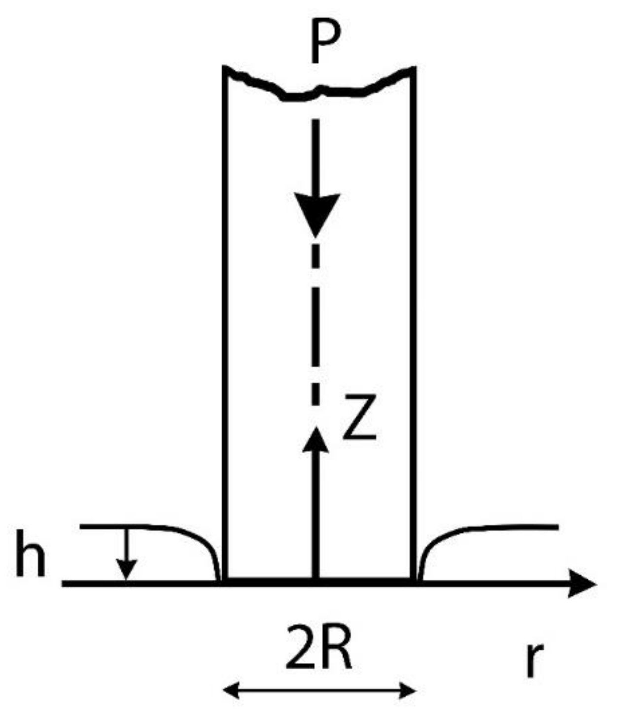
2. Cylindrical Punch Indentation: Theory and Experiments
τrz (r,0) = 0 0 ≤ r ≤ R
uz (r,0) = h 0 ≤ r ≤ R
3. Case Studies
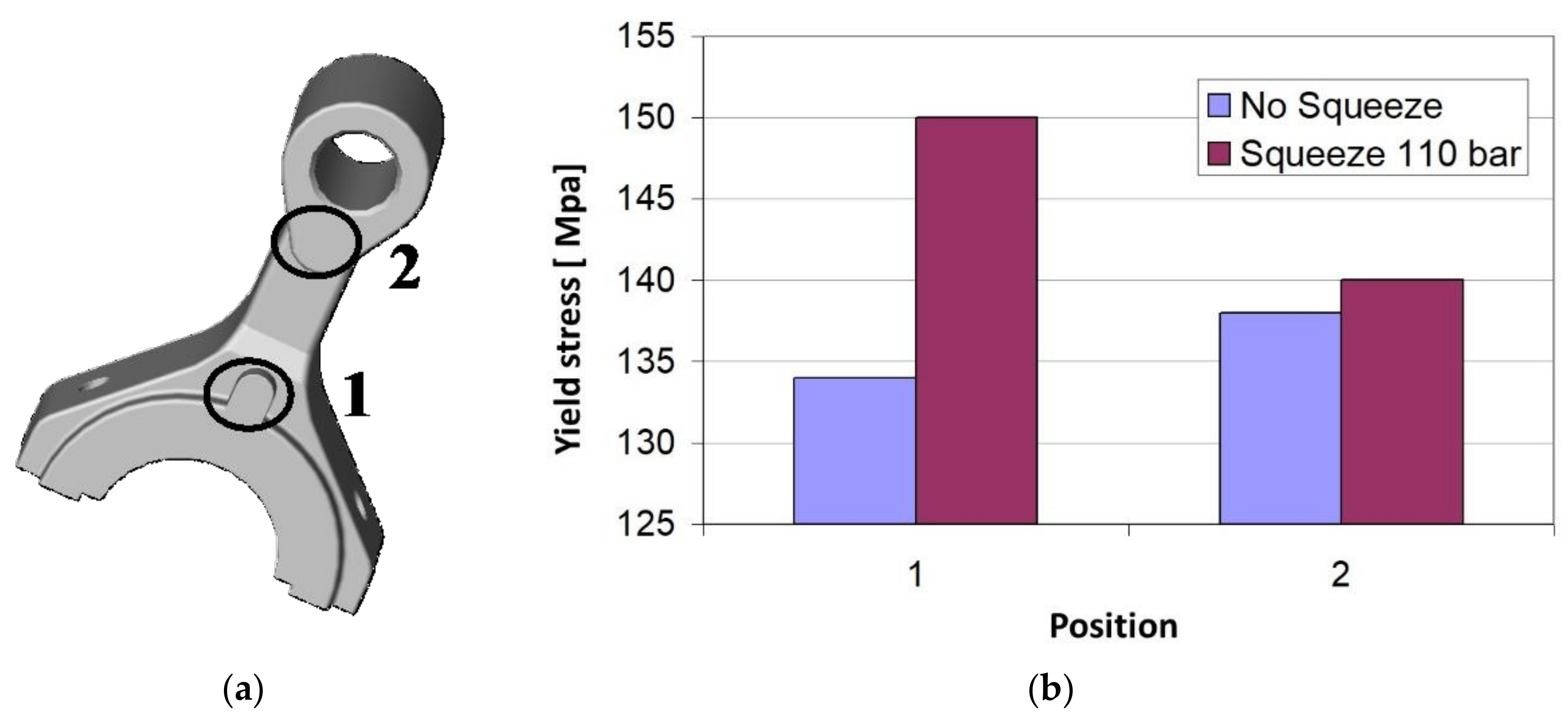
3.1. Crank Manufacturing through Pin Squeeze Casting
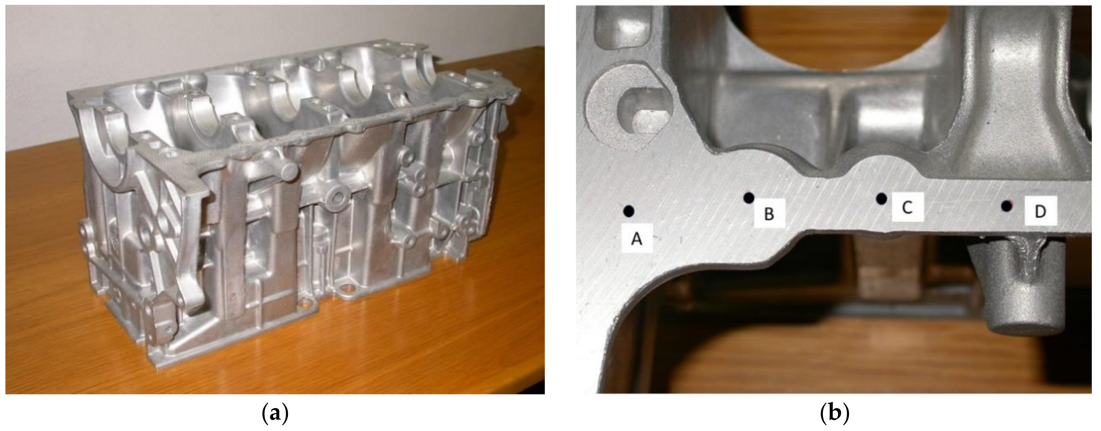
3.2. Evaluation of the Local Mechanical Properties in a Carter of Complex Geometry
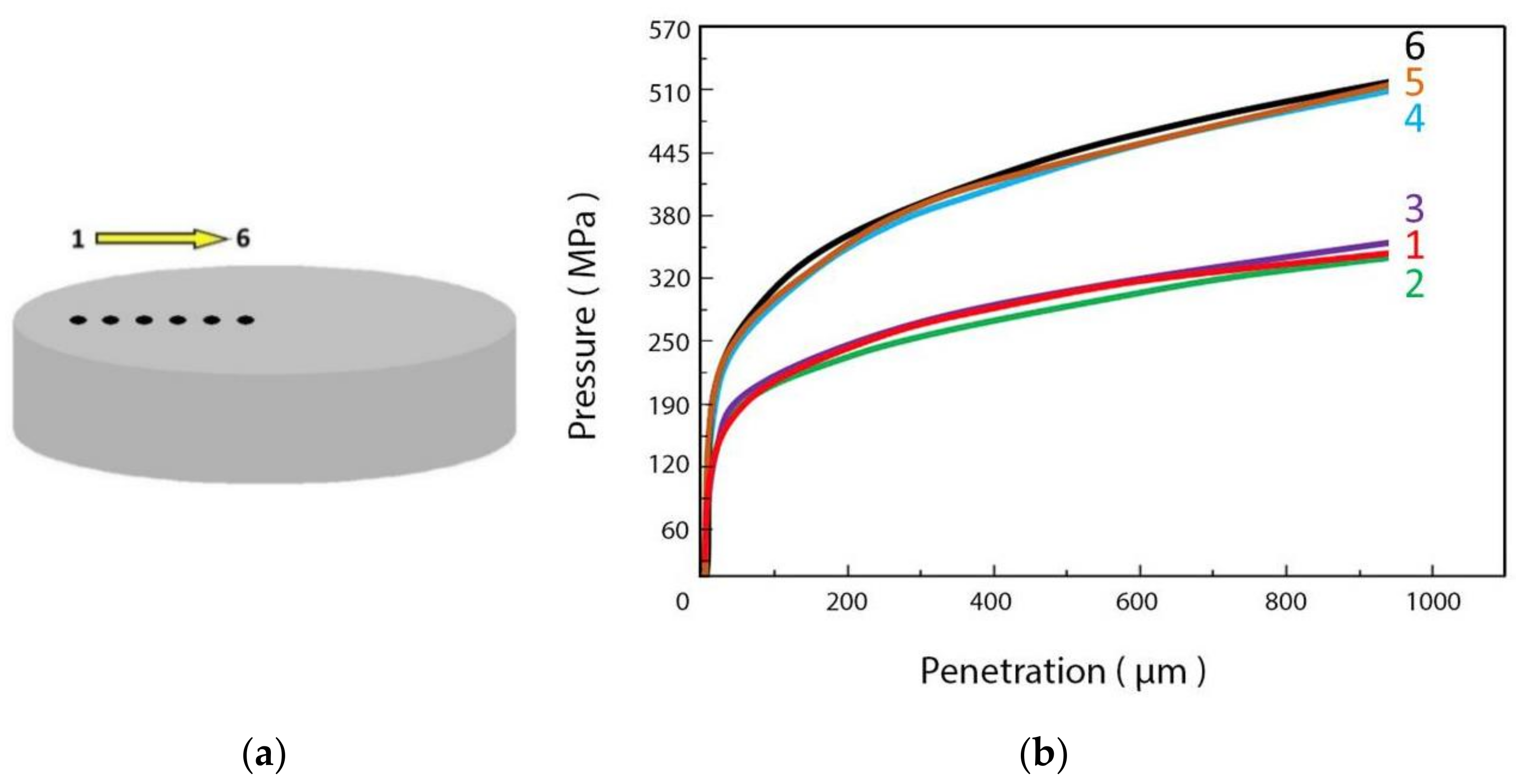
3.3. Qualification of Aluminium Billets for Extrusion
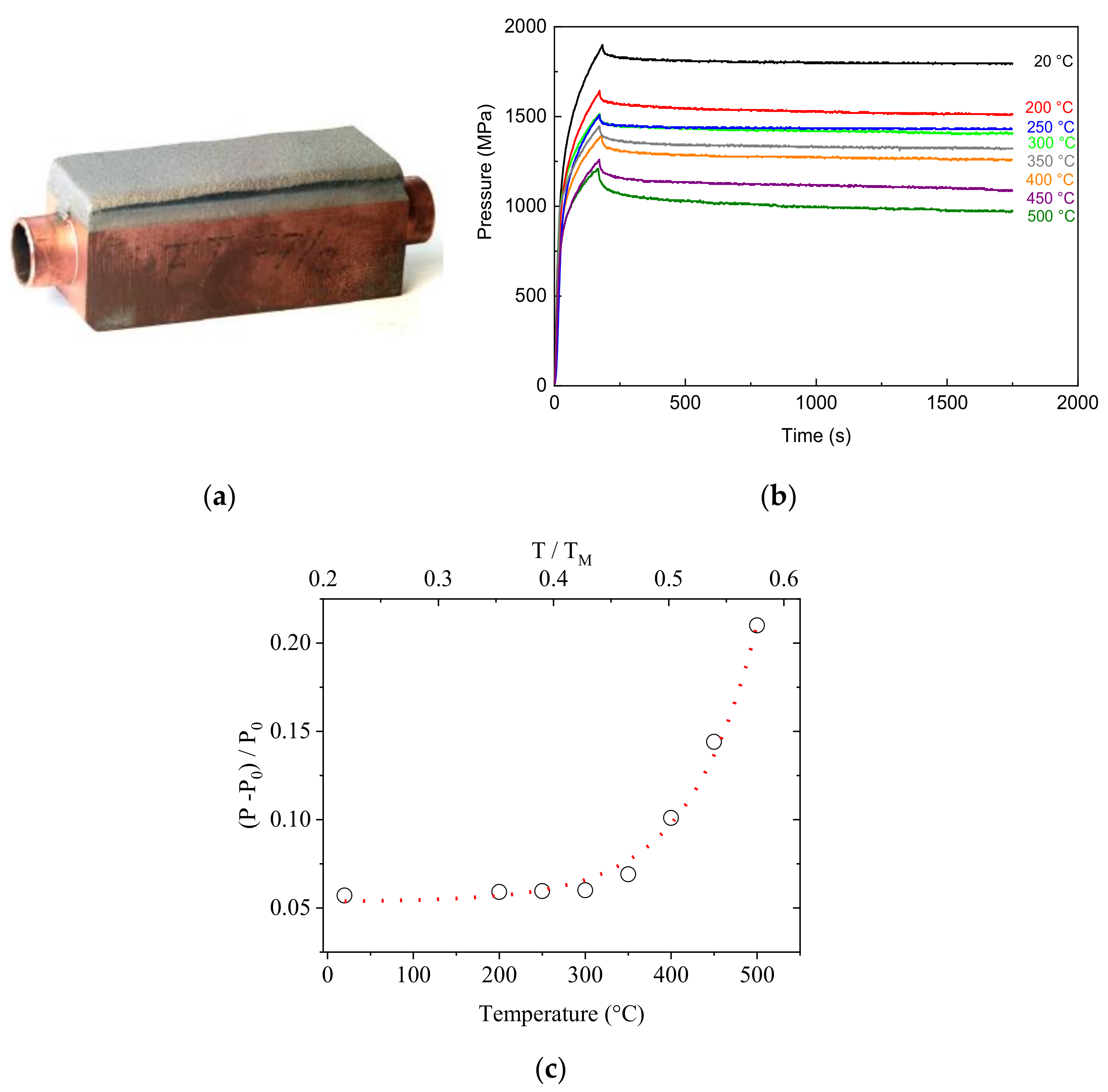
3.4. Stress-Relaxation Tests on CuCrZr Heat Sinks
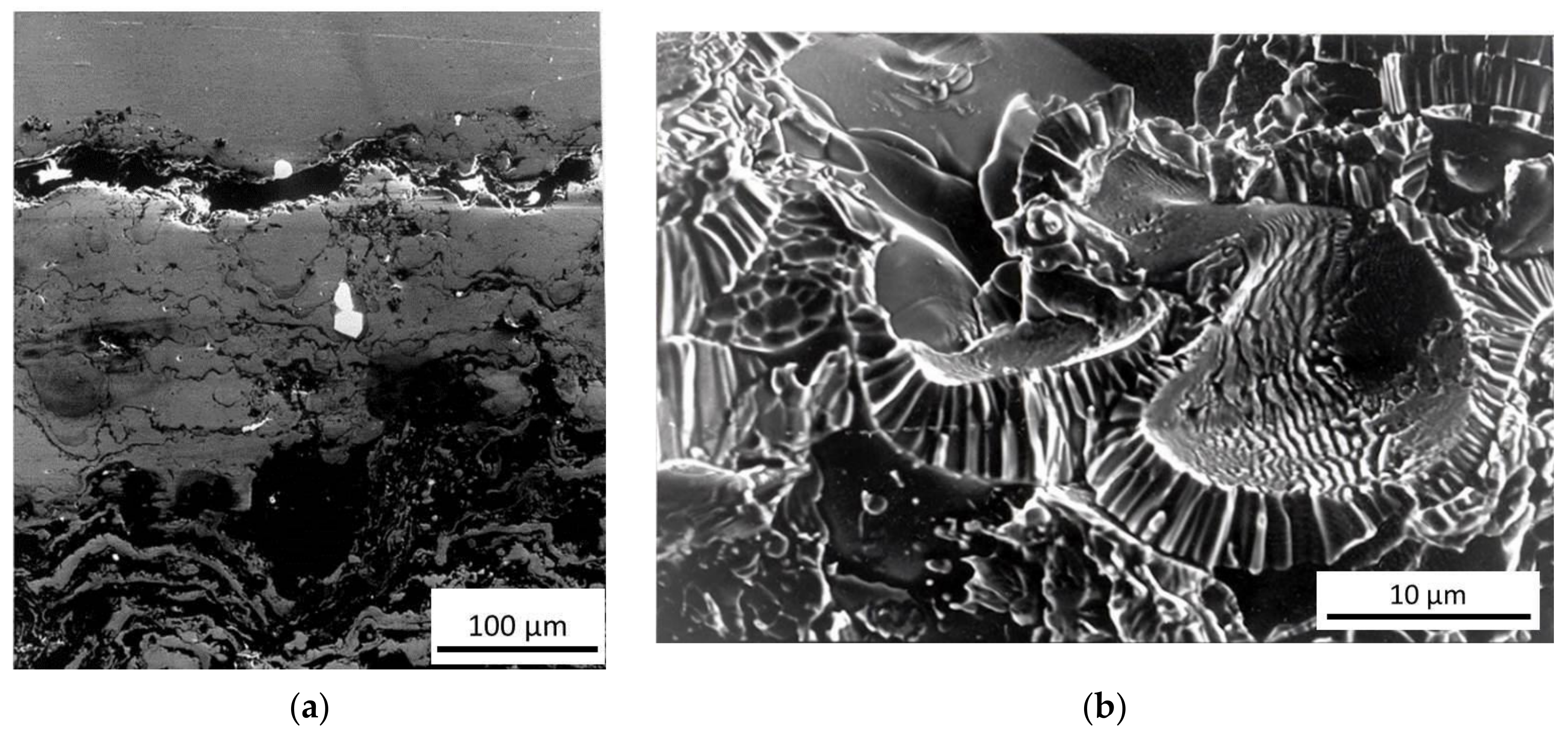
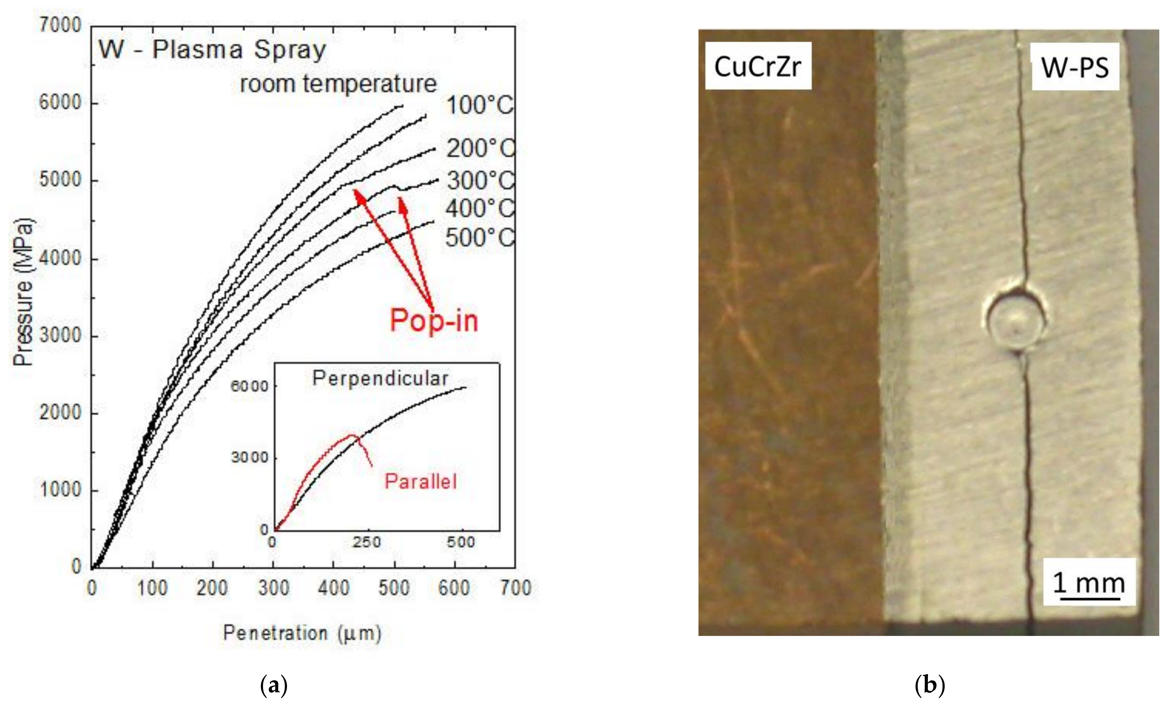
3.5. Characterization of Thick W Coatings on CuCrZr Alloy
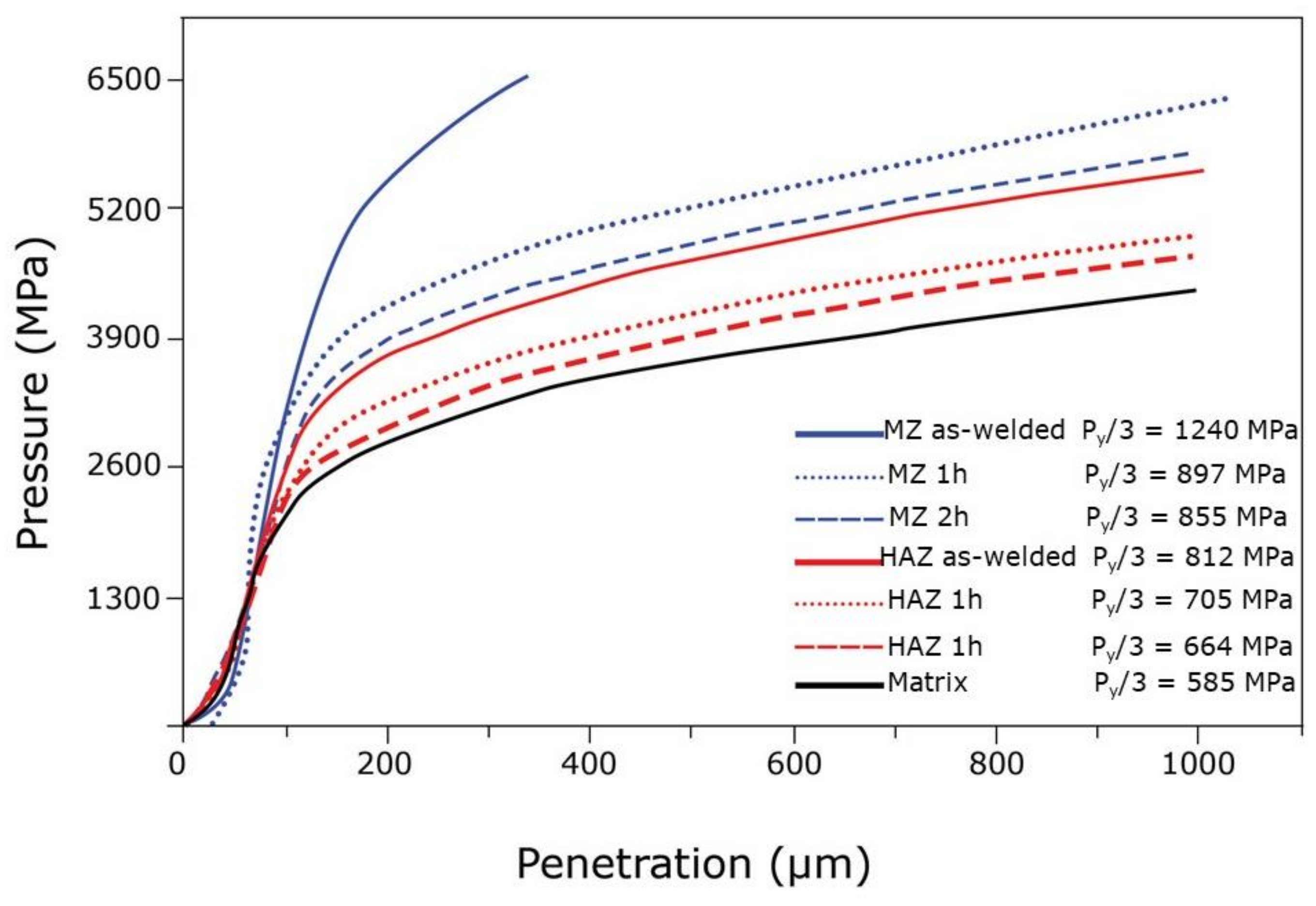
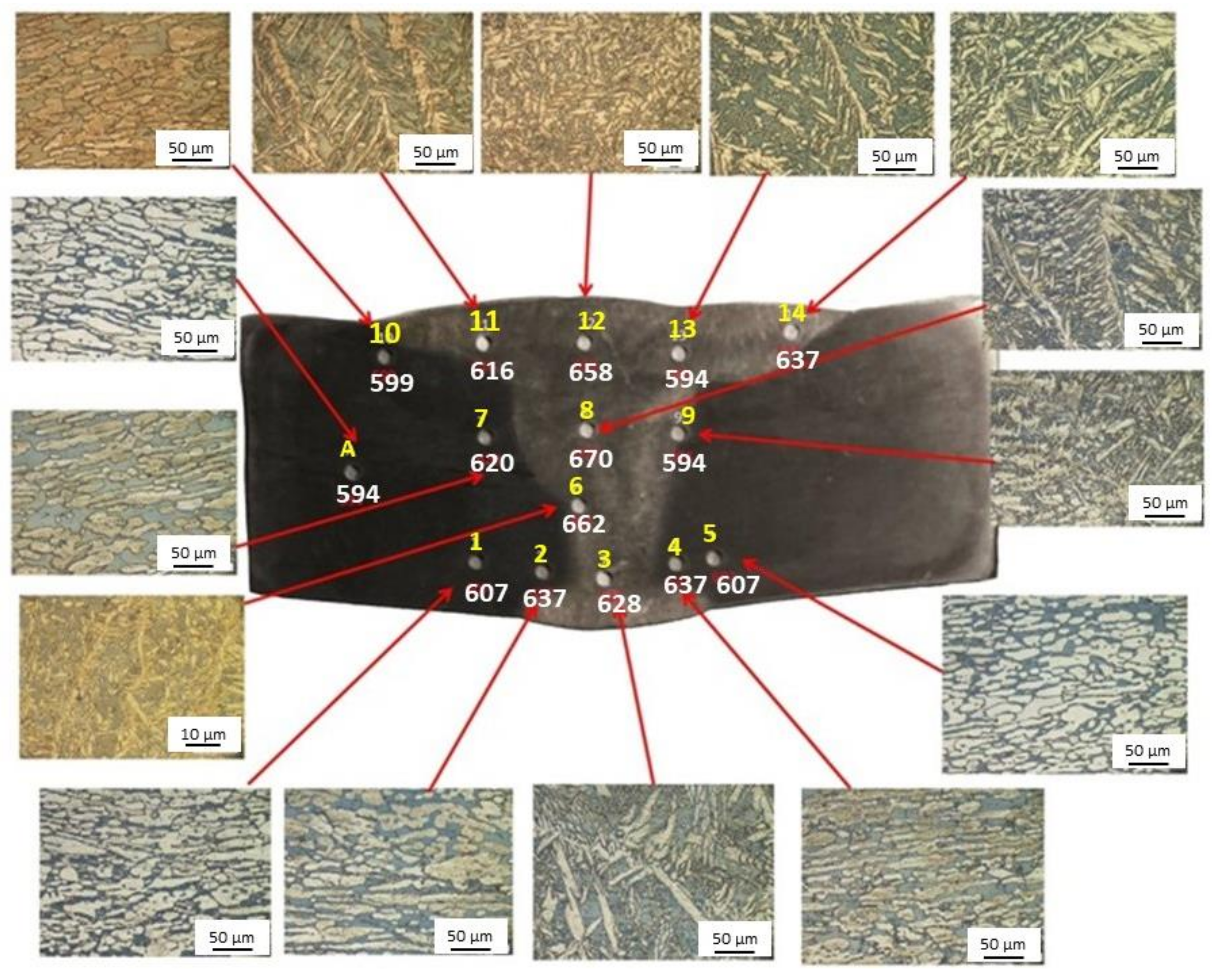
3.6. Measure of the Local Mechanical Properties of the MZ and the HAZ in Welded Joints
4. Conclusions
Author Contributions
Funding
Institutional Review Board Statement
Informed Consent Statement
Data Availability Statement
Conflicts of Interest
Nomenclature
| R | indenter tip radius |
| r | distance from the center of cylindrical indenter |
| h | indenter penetration depth |
| σz | normal stress in z direction |
| τrz | shear stress in the rz plane |
| uz | displacement in z direction |
| Pm | mean contact pressure |
| Pmax | maximum contact pressure |
| E | Young’s modulus |
| ν | Poisson’s ratio |
| (r, θ, z) | local cylindrical coordinate system |
| σr | normal stress in r direction |
| σθ | normal stress in θ direction |
| ξ | shear strength |
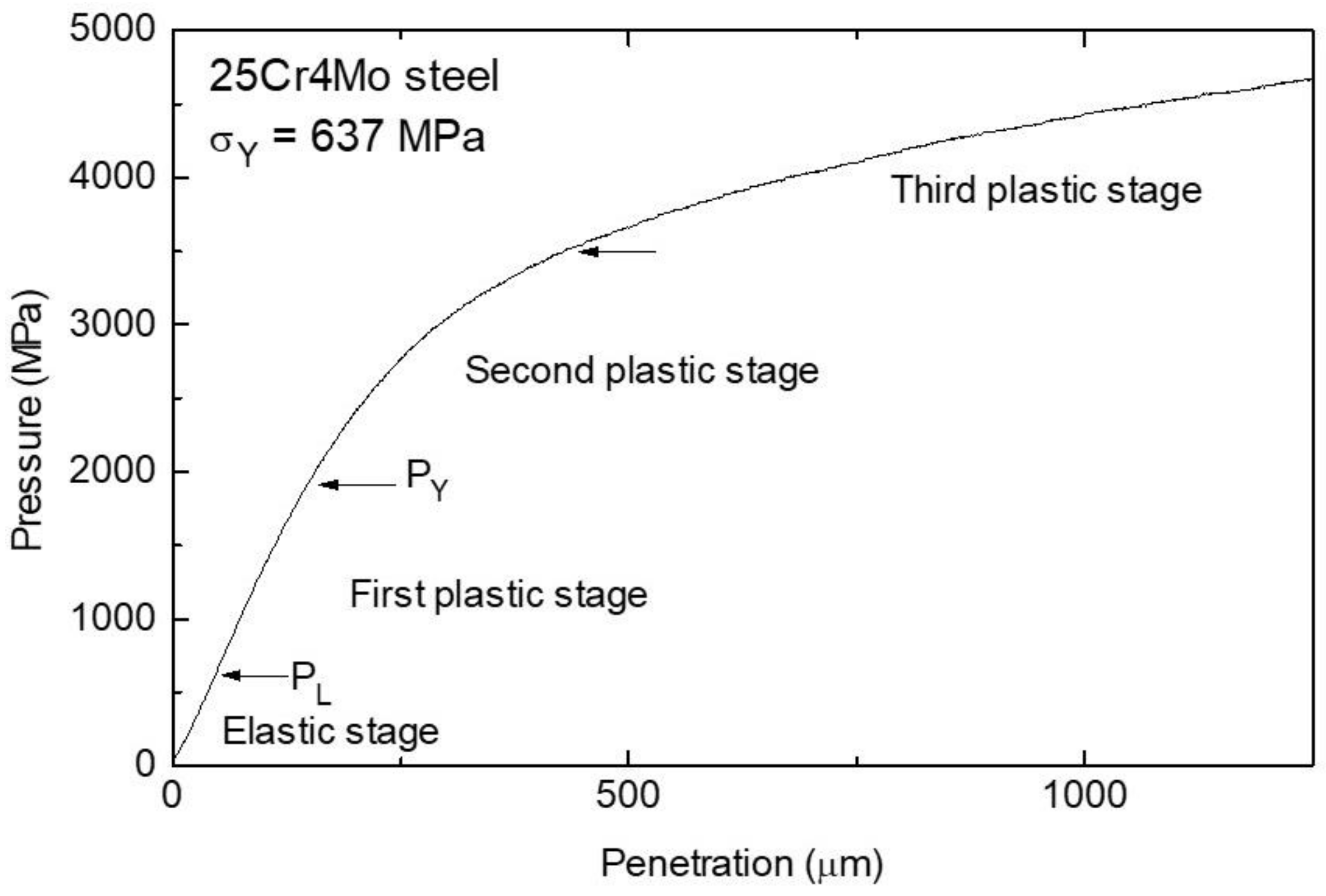
| Py | upper limit of the first plastic stage of the experimental pressure-penetration curve |
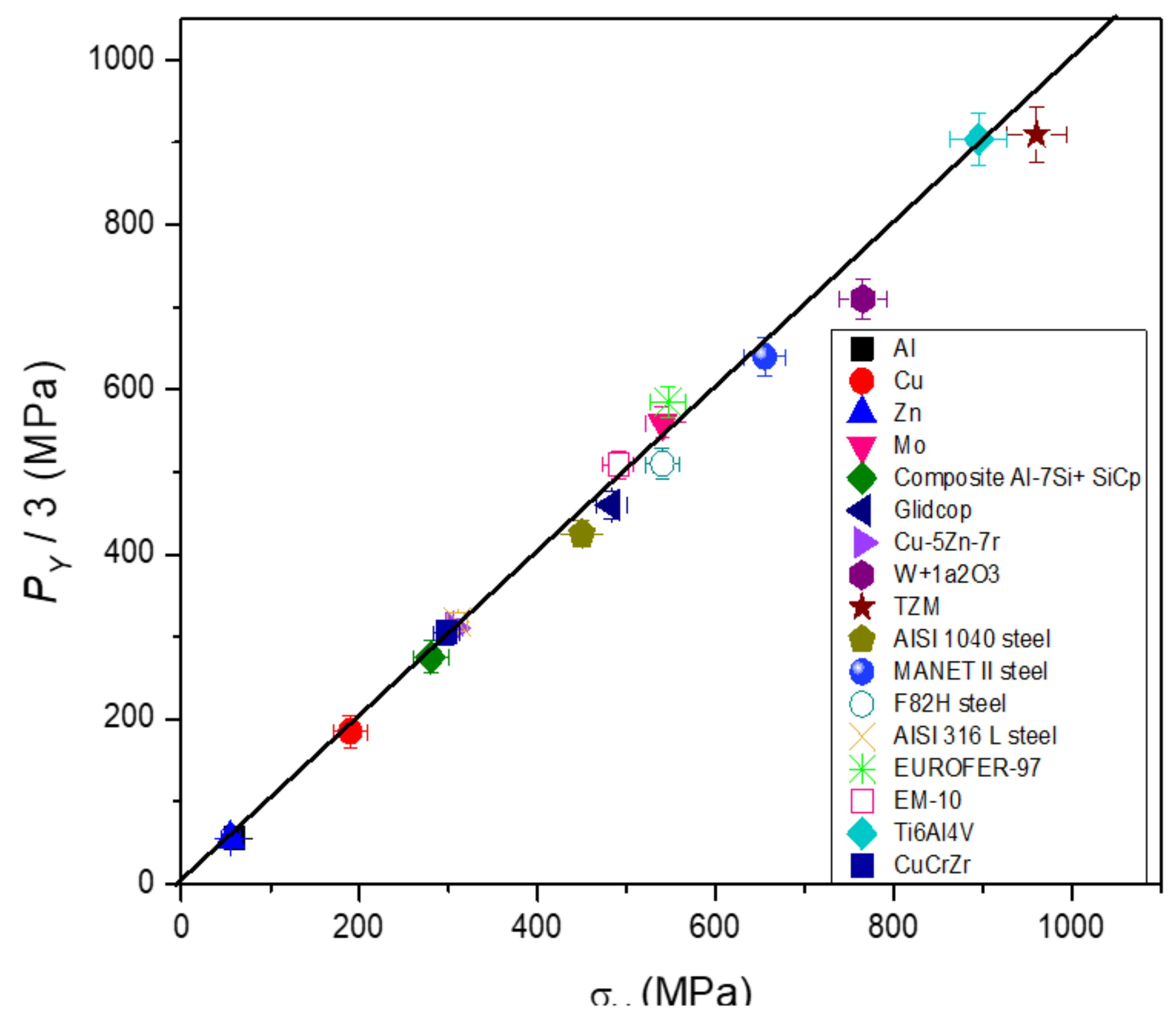
| σy | yield stress |
| P0 | initial pressure in stress relaxation tests |
| t | time |
| τ | relaxation time in stress relaxation tests |
| FIMEC | Flat top Indenter for Mechanical Characterization |
| IFMIF | International Fusion Materials Irradiation Facility |
| CFRP | Carbon Fiber Reinforced Polymer |
| DBTT | ductile to brittle transition temperature |
| CRB | cracked Round Bar |
| ISE | indentation size effect |
| PS | plasma spray |
| VW | volume fraction of W in the graded layers between CuCrZr substrate and pure W coating |
| x | distance from the pure W coating |
| t | interlayer thickness |
| p | gradient index |
| TIG | tungsten inert gas |
| MIG | metal-arc inert gas |
| GTAW | gas tungsten arc welding |
| HAZ | heat affected zone |
| MZ | molten zone |
| PWHT | post welding heat treatment |
| TBM | Test Blanket Module of ITER |
| ITER | International Thermonuclear Experimental Reactor |
| DSS | duplex stainless steel |
| SP | second phase |
| SEM | scanning electron microscopy |
| TEM | transmission electron microscopy |
References
- Gondi, P.; Montanari, R.; Sili, A. Small scale non-destructive stress-strain and creep tests feasible during irradiation. J. Nucl. Mater 1994, 212–215, 1688–1692. [Google Scholar] [CrossRef]
- Gondi, P.; Donato, A.; Montanari, R.; Sili, A. A miniaturized test method for the mechanical characterization of structural materials for fusion reactors. J. Nucl. Mater. 1996, 233–237, 1557–1560. [Google Scholar] [CrossRef]
- Gondi, P.; Montanari, R.; Sili, A.; Foglietta, S.; Donato, A.; Filacchioni, G. Applicability of the FIMEC indentation test to characterize materials irradiated in the future IFMIF high intensity neutron irradiation source. Fusion Technol. 1996, 1607. Available online: http://hdl.handle.net/2108/50374 (accessed on 16 March 2021).
- Donato, A.; Gondi, P.; Montanari, R.; Moreschi, L.; Sili, A.; Storai, S. A remotely operated FIMEC apparatus for the mechanical characterization of neutron irradiated materials. J. Nucl. Mater. 1998, 258–263, 446–451. [Google Scholar] [CrossRef]
- Riccardi, B.; Montanari, R.; Moreschi, L.F.; Sili, A.; Storai, S. Mechanical characterization of fusion materials by indentation test. Fusion Eng. Des. 2001, 58–59, 755–759. [Google Scholar] [CrossRef]
- Riccardi, B.; Montanari, R. Indentation of metals by a flat-ended cylindrical punch. Mater. Sci. Eng. A 2004, 381, 281–291. [Google Scholar] [CrossRef]
- Montanari, R.; Filacchioni, G.; Iacovone, B.; Plini, P.; Riccardi, B. High temperature indentation tests on fusion reactor candidate materials. J. Nucl. Mater. 2007, 367–370, 648–652. [Google Scholar] [CrossRef]
- Missori, S.; Montanari, R.; Sili, A. Caratterizzazione meccanica mediante prove FIMEC di giunti saldati in lega Al 6082. La Metall. Ital. 2001, 3, 35. [Google Scholar]
- Filacchioni, G.; Montanari, R.; Tata, M.; Pilloni, L. Structural and mechanical properties of welded joints of reduced activation martensitic steels. J. Nucl. Mater. 2002, 307–311, 1563–1567. [Google Scholar] [CrossRef]
- Montanari, R.; Filacchioni, G.; Riccardi, B.; Tata, M.E.; Costanza, G. Characterization of eurofer-97 TIG-welded joints by FIMEC indentation tests. J. Nucl. Mater. 2004, 329–333, 1529–1533. [Google Scholar] [CrossRef]
- Yang, F.; Li, J.C.M. Impression test—A review. Mater. Sci. Eng. R 2013, 74, 233–253. [Google Scholar] [CrossRef]
- Lu, Y.C.; Kurapati, S.N.V.R.K.; Yang, F. Finite element analysis of cylindrical indentation for determining plastic properties of materials in small volumes. J. Phys. D Appl. Phys. 2008, 41, 115415. [Google Scholar] [CrossRef]
- Casamichele, L.; Quadrini, F.; Tagliaferri, V. Non-destructive evaluation of local mechanical properties of Al die cast large components by means of FIMEC indentation test. Measurement 2007, 40, 892–897. [Google Scholar] [CrossRef]
- Genna, S.; Trovalusci, F.; Tagliaferri, V. Indentation test to study the moisture absorption effect on CFRP composite. Compos. Part B Eng. 2017, 124, 1–8. [Google Scholar] [CrossRef]
- David, F.; Moretti, P.; Tagliaferri, V.; Trovalusci, F. FIMEC test to evaluate the water uptake of coated and uncoated CFRP composites. Materials 2020, 13, 1154. [Google Scholar] [CrossRef]
- Xu, B.; Wang, X.; Zhao, B.; Yue, Z. Study of crystallographic creep parameters of nickel-based single crystal superalloys by indentation method. Mater. Sci. Eng. A 2008, 478, 187–194. [Google Scholar] [CrossRef]
- Midawi, A.R.H.; Huda, N.; Simha, C.H.M.; Gerlich, A.P. Characterization of anisotropy of strength in API-X80 line pipe welds through instrumented indentation. Met. Microstruct. Anal. 2020, 9, 884–894. [Google Scholar] [CrossRef]
- Kim, W.; Choi, S.; Kim, J.; Jeon, S.-W.; Choi, M.-J.; Kwon, D. Estimation of fracture toughness using flat-ended cylindrical indentation. Met. Mater. Int. 2020, 1–9. [Google Scholar] [CrossRef]
- Ozcan, S.; Tezcan, J.; Gurung, B.; Filip, P. The effect of heat treatment temperature on the interfacial shear strength of C/C composites. J. Mater. Sci. 2011, 46, 38–46. [Google Scholar] [CrossRef]
- Mohammed, A.S.K.; Sehitoglu, H.; Rateick, R. Interface graphitization of carbon-carbon composites by nanoindentation. Carbon 2019, 150, 425–435. [Google Scholar] [CrossRef]
- Brezmes, A.O.; Breitkopf, C. Influence of indenter tip diameter and film thickness on flat indentations into elastic-plastic films by means of the finite element method. Thin Solid Films 2018, 653, 49–56. [Google Scholar] [CrossRef]
- Hertz, H. Uber die Beruhrung fester Elastischer Korper (on the contact of elastic solids). Reine Angew. Math. 1882, 92, 156–171. [Google Scholar]
- Cerruti, V. Memorie di Fisica Matematica; Accademia dei Lincei: Roma, Italy, 1882. [Google Scholar]
- Boussinesq, J. Application des Potentiels a l’Etude de l’Equilibre et du Mouvement de Solides Elastiques; Gautier-Villar: Paris, France, 1885. [Google Scholar]
- Love, A.E.H. A Treatise on the Mathematical Theory of Elasticity, 4th ed.; Dover: New York, NY, USA, 1944. [Google Scholar]
- Sneddon, I.N. The relation between load and penetration in the axisymmetric boussinesq problem for a punch of arbitrary profile. Int. J. Eng. Sci. 1965, 3, 47–57. [Google Scholar] [CrossRef]
- Timoshenko, S.; Godier, J.N. Theory of Elasticity, 3rd ed.; Mc Graw Hill: New York, NY, USA, 1951; p. 408. [Google Scholar]
- Tranter, C.J.; Sneddon, I.N. Fourier transforms. Math. Gaz. 1952, 36, 290. [Google Scholar] [CrossRef]
- Bishop, R.F.; Hill, R.; Mott, N.F. The Theory of Indentation and Hardness Tests. In Proceedings of the Physical Society; IOP Publishing: Bristol, UK, 1945; Volume 57, pp. 147–159. [Google Scholar]
- Johnson, K.L. Contact Mechanics; Cambridge University Press: Cambridge, UK, 1985; pp. 153–201. [Google Scholar]
- Shield, R.T. On the plastic flow of metals under conditions of axial symmetry. Proc. R. Soc. A 1955, 233, 267–287. [Google Scholar]
- Eason, G.; Shield, R.T. The plastic indentation of a semi-infinite solid by a perfectly rough circular punch. Z. Angew. Math. Phys. 1960, 11, 33–43. [Google Scholar] [CrossRef]
- Yu, H.Y.; Imam, M.A.; Rath, B.B. Study of the deformation behavior of homogeneous materials by impression tests. J. Mater. Sci. 1985, 20, 636–642. [Google Scholar] [CrossRef]
- Ciavarella, M.; Hills, D.A.; Monno, G. The influence of rounded edges on indentation by a flat punch. Proc. Instn. Mech. Eng. 1998, 212, 319–328. [Google Scholar] [CrossRef]
- Scibetta, E.; Lucon, R.; Chaouadi, E.; Walle, W. Instrumented hardness testing using a flat punch. Int. J. Pres. Ves. Pip. 2003, 80, 345–349. [Google Scholar] [CrossRef]
- Ciambella, L.; Montanari, R. New algorithm to determine the yield stress from FIMEC test. Mater. Sci. Forum 2014, 783–786, 2272–2277. [Google Scholar] [CrossRef]
- Brutti, C. A theoretical model for elastic-perfectly plastic flat cylindrical punch indentation. Mech. Mater. 2021, 155, 103770. [Google Scholar] [CrossRef]
- Christ, B.W. Effect of Specimen Preparation, Setup and Test Procedures on Test Results. Metals Handbook, 9th ed.; ASM International: Chicago, IL, USA; Volume 8, p. 32.
- Nix, W.D.; Gao, H. Indentation size effects in crystalline materials: A law for strain gradient plasticity. J. Mech. Phys. Solids 1998, 46, 411–425. [Google Scholar] [CrossRef]
- Campbell, C.; Gill, S. An analytical model for the flat punch indentation size effect. Int. J. Solids Struct. 2019, 171, 81–91. [Google Scholar] [CrossRef]
- Chen, K.; Meng, W.; Mei, F.; Hiller, J.; Miller, D. From micro- to nano-scale molding of metals: Size effect during molding of single crystal Al with rectangular strip punches. Acta Mater. 2011, 59, 1112–1120. [Google Scholar] [CrossRef]
- You, J.; Visca, E.; Bachmann, C.; Barrett, T.; Crescenzi, F.; Fursdon, M.; Greuner, H.; Guilhem, D.; Languille, P.; Li, M.; et al. European DEMO divertor target: Operational requirements and material-design interface. Nucl. Mater. Energy 2016, 9, 171–176. [Google Scholar] [CrossRef]
- Mao, X.; Fursdon, M.; Chang, X.; Zhang, J.; Liu, P.; Ellwood, G.; Qian, X.; Qin, S.; Peng, X.; Barrett, T. Exploring the engineering limit of heat flux of a W/RAFM divertor target for fusion reactors. Nucl. Fusion 2018, 58, 066014. [Google Scholar] [CrossRef]
- Lu, K.; Liu, P.; Qian, X.; Mao, X.; Zhang, J.; Peng, X.; Qin, S.; Song, Y. Fatigue and fracture analysis on EAST divertor monoblock heat sink in H-mode operation. Fusion Eng. Des. 2018, 137, 30–34. [Google Scholar] [CrossRef]
- Zhang, K.; Gaganidze, E.; Gorley, M. Development of the material property handbook and database of CuCrZr. Fusion Eng. Des. 2019, 144, 148–153. [Google Scholar] [CrossRef]
- Liu, P.; Qian, X.; Mao, X.; Song, W.; Peng, X. Study on creep-fatigue of heat sink in W/CuCrZr divertor target based on a new approach to creep life. Nucl. Mater. Energy 2020, 25, 100846. [Google Scholar] [CrossRef]
- Linke, J.M.; Hirai, T.; Rödig, M.; Singheiser, L.A. Performance of plasma-facing materials under intense thermal loads in tokamaks and stellarators. Fusion Sci. Technol. 2017, 46, 142–151. [Google Scholar] [CrossRef]
- Linke, J.; Du, J.; Loewenhoff, T.; Pintsuk, G.; Spilker, B.; Steudel, I.; Wirtz, M. Challenges for plasma-facing components in nuclear fusion. Matter Radiat. Extremes 2019, 4, 056201. [Google Scholar] [CrossRef]
- Riccardi, B.; Pizzuto, A.; Orsini, A.; Libera, S.; Visca, E.; Bertamini, L.; Casadei, F.; Severini, E.; Montanari, R.; Vesprini, R. Tungsten thick coatings for plasma facing components. Fusion Technol. 1998, 31, 223–226. [Google Scholar]
- Barabash, V.; Akiba, M.; Cardella, A.; Mazul, I.; Odegard, B.C.; Ploechl, L.; Tivey, R.; Vieider, G. Armor and heat sink materials joining technologies development for ITER plasma facing components. J. Nucl. Mater. 2000, 283–287, 1248–1252. [Google Scholar] [CrossRef]
- Montanari, R.; Riccardi, B.; Volterri, R.; Bertamini, L. Characterisation of plasma sprayed W coatings on a CuCrZr alloy for nuclear fusion reactor applications. Mater. Lett. 2002, 52, 100–105. [Google Scholar] [CrossRef]
- Riccardi, B.; Montanari, R.; Casadei, M.; Costanza, G.; Filacchioni, G.; Moriani, A. Optimisation and characterisation of tungsten thick coatings on copper based alloy substrates. J. Nucl. Mater. 2006, 352, 29–35. [Google Scholar] [CrossRef]
- Linsmeier, C.; Rieth, M.; Aktaa, J.; Chikada, T.; Hoffmann, A.; Houben, A.; Kurishita, H.; Jin, X.; Li, M.; Litnovsky, A.; et al. Development of advanced high heat flux and plasma-facing materials. Nucl. Fusion 2017, 57, 092007. [Google Scholar] [CrossRef]
- Angella, G.; Fava, A.; Montanari, R.; Richetta, M.; Varone, A. Flat-top cylinder indenter examination of duplex stainless steel 2205 after different heat treatments. Metals 2017, 7, 178. [Google Scholar] [CrossRef]
- Abou-Sena, A.; Löbbecke, B.; Von Der Weth, A.; Knitter, R. Effect of post welding heat treatment of the HCPB TBM on Eurofer and lithium orthosilicate pebbles. Fusion Eng. Des. 2011, 86, 2254–2257. [Google Scholar] [CrossRef]
- ASTM. A928/A928M-08a, Standard Specification for Ferritic/Austenitic (Duplex) Stainless Steel Pipe Electric Fusion Welded with Addition of Filler Metal. Available online: http://www.astm.org/Standards/A928.htm (accessed on 16 March 2021).
- Solomon, H.D.; Devine, T.M. Duplex stainless steels—A tale of two phases. In Proceedings of the Conference on Duplex Stainless Steels, St. Louis, MO, USA, 23–28 October 1982; pp. 693–756. [Google Scholar]
- Fargas, G.; Anglada, M.; Mateo, A. Effect of the annealing temperature on the mechanical properties, formability and corrosion resistance of hot-rolled duplex stainless steel. J. Mater. Process. Technol. 2009, 209, 1770–1782. [Google Scholar] [CrossRef]
- Calliari, I.; Pellizzari, M.; Zanellato, M.; Ramous, E. The phase stability in Cr-Ni and Cr-Mn duplex stainless steels. J. Mater. Sci. 2011, 46, 6916–6924. [Google Scholar] [CrossRef]
- Chan, K.W.; Tjong, S.C. Effect of secondary phase precipitation on the corrosion behavior of duplex stainless steels. Materials 2014, 7, 5268–5304. [Google Scholar] [CrossRef]
- Chen, T.; Weng, K.; Yang, J. The effect of high-temperature exposure on the microstructural stability and toughness property in a 2205 duplex stainless steel. Mater. Sci. Eng. A 2002, 338, 259–270. [Google Scholar] [CrossRef]
- Akisanya, A.R.; Obi, U.; Renton, N.C. Effect of ageing on phase evolution and mechanical properties of a high tungsten super-duplex stainless steel. Mater. Sci. Eng. A 2012, 535, 281–289. [Google Scholar] [CrossRef]
- Badji, R.; Bouabdallah, M.; Bacroix, B.; Kahloun, C.; Bettahar, K.; Kherrouba, N. Effect of solution treatment temperature on the precipitation kinetic of σ-phase in 2205 duplex stainless steel welds. Mater. Sci. Eng. A 2008, 496, 447–454. [Google Scholar] [CrossRef]
- Pohl, M.; Storz, O.; Glogowski, T. Effect of intermetallic precipitations on the properties of duplex stainless steel. Mater. Charact. 2007, 58, 65–71. [Google Scholar] [CrossRef]


| Temperature (°C) | 25 | 100 | 200 | 300 | 400 | 500 |
|---|---|---|---|---|---|---|
| PY/3 (MPa) | 794 | 615 | 575 | 488 | 425 | 410 |
| Cr | C | Si | Mn | P | S | Mo | W | V | Ta | Ti | N |
|---|---|---|---|---|---|---|---|---|---|---|---|
| 8.87 | 0.10 | 0.05 | 0.45 | 0.005 | 0.004 | 0.0027 | 1.15 | 0.20 | 0.14 | 0.005 | 0.017 |
| Ni | Cu | Co | Al | Nb | B | O | As | Sn | Zr | Sb | Fe |
| 0.028 | 0.0035 | 0.006 | 0.008 | 0.0025 | <0.001 | 0.0009 | <0.005 | <0.005 | <0.005 | <0.005 | to balance |
| C | Cr | Cu | Mn | Mo | N | Ni | Si | P | S | |
|---|---|---|---|---|---|---|---|---|---|---|
| UNS 31803 | <0.03 | 21–23 | | <0.2 | 2.5–3.5 | 0.15–020 | 4.5–6.5 | <0.1 | <0.03 | <0.02 |
| Filling material | 0.014 | 22.95 | 0.10 | 1.52 | 3.08 | 0.163 | 8.61 | 0.42 | 0.015 | 0.0008 |
| Point | 1 | 2 | 3 | 4 | 5 | 6 | 7 | |
|---|---|---|---|---|---|---|---|---|
| Zone | HAZ | HAZ | MZ | HAZ | HAZ | MZ | HAZ | |
| PY/3 | 607 | 637 | 628 | 637 | 607 | 662 | 620 | |
| HV | 278 | 275 | 284 | 274 | 289 | 290 | 285 | |
| HV/ PY/3 | 0.46 | 0.43 | 0.45 | 0.43 | 0.48 | 0.44 | 0.46 | |
| Point | 8 | 9 | 10 | 11 | 12 | 13 | 14 | A |
| Zone | MZ | MZ | HAZ | MZ | MZ | MZ | MZ | BM |
| PY/3 | 670 | 594 | 599 | 616 | 658 | 594 | 637 | 594 |
| HV | 290 | 289 | 256 | 275 | 280 | 279 | 283 | 256 |
| HV/ PY/3 | 0.43 | 0.48 | 0.43 | 0.44 | 0.43 | 0.47 | 0.44 | 0.43 |
| C | Cr | Mn | Mo | N | Ni | Si | P | S | Fe |
|---|---|---|---|---|---|---|---|---|---|
| <0.03 | 21–23 | <0.2 | 2.5–3.5 | 0.15–0.20 | 4.5–6.5 | <0.1 | <0.03 | <0.02 | to balance |
Publisher’s Note: MDPI stays neutral with regard to jurisdictional claims in published maps and institutional affiliations. |
© 2021 by the authors. Licensee MDPI, Basel, Switzerland. This article is an open access article distributed under the terms and conditions of the Creative Commons Attribution (CC BY) license (https://creativecommons.org/licenses/by/4.0/).
Share and Cite
Montanari, R.; Varone, A. Flat-Top Cylinder Indenter for Mechanical Characterization: A Report of Industrial Applications. Materials 2021, 14, 1742. https://doi.org/10.3390/ma14071742
Montanari R, Varone A. Flat-Top Cylinder Indenter for Mechanical Characterization: A Report of Industrial Applications. Materials. 2021; 14(7):1742. https://doi.org/10.3390/ma14071742
Chicago/Turabian StyleMontanari, Roberto, and Alessandra Varone. 2021. "Flat-Top Cylinder Indenter for Mechanical Characterization: A Report of Industrial Applications" Materials 14, no. 7: 1742. https://doi.org/10.3390/ma14071742
APA StyleMontanari, R., & Varone, A. (2021). Flat-Top Cylinder Indenter for Mechanical Characterization: A Report of Industrial Applications. Materials, 14(7), 1742. https://doi.org/10.3390/ma14071742