
Porous Structure of Ultra-High-Performance Fibre-Reinforced Concretes


Abstract
1. Introduction
2. Materials and Methods
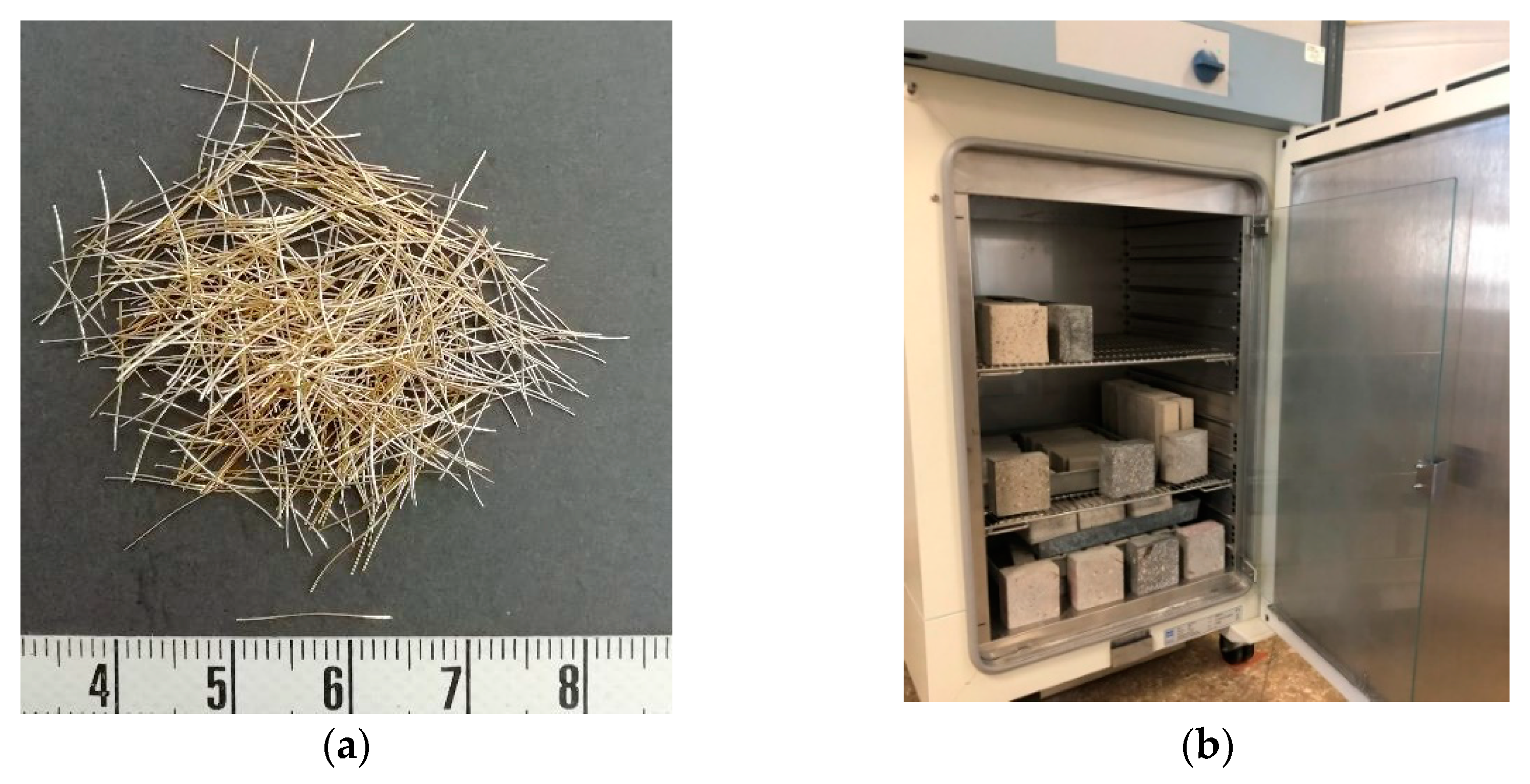
2.1. Concrete Mixtures and Materials
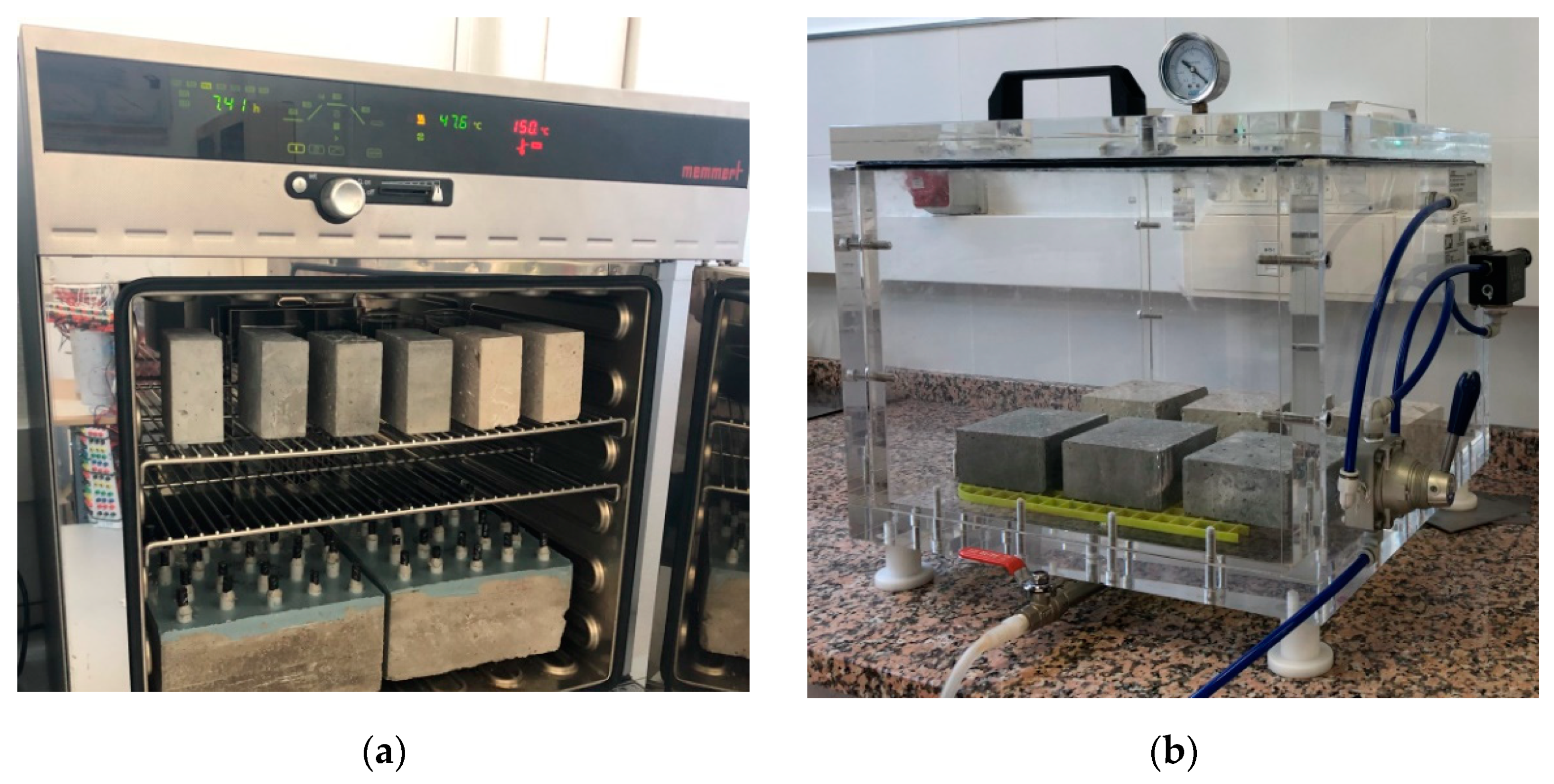
2.2. Test Methods
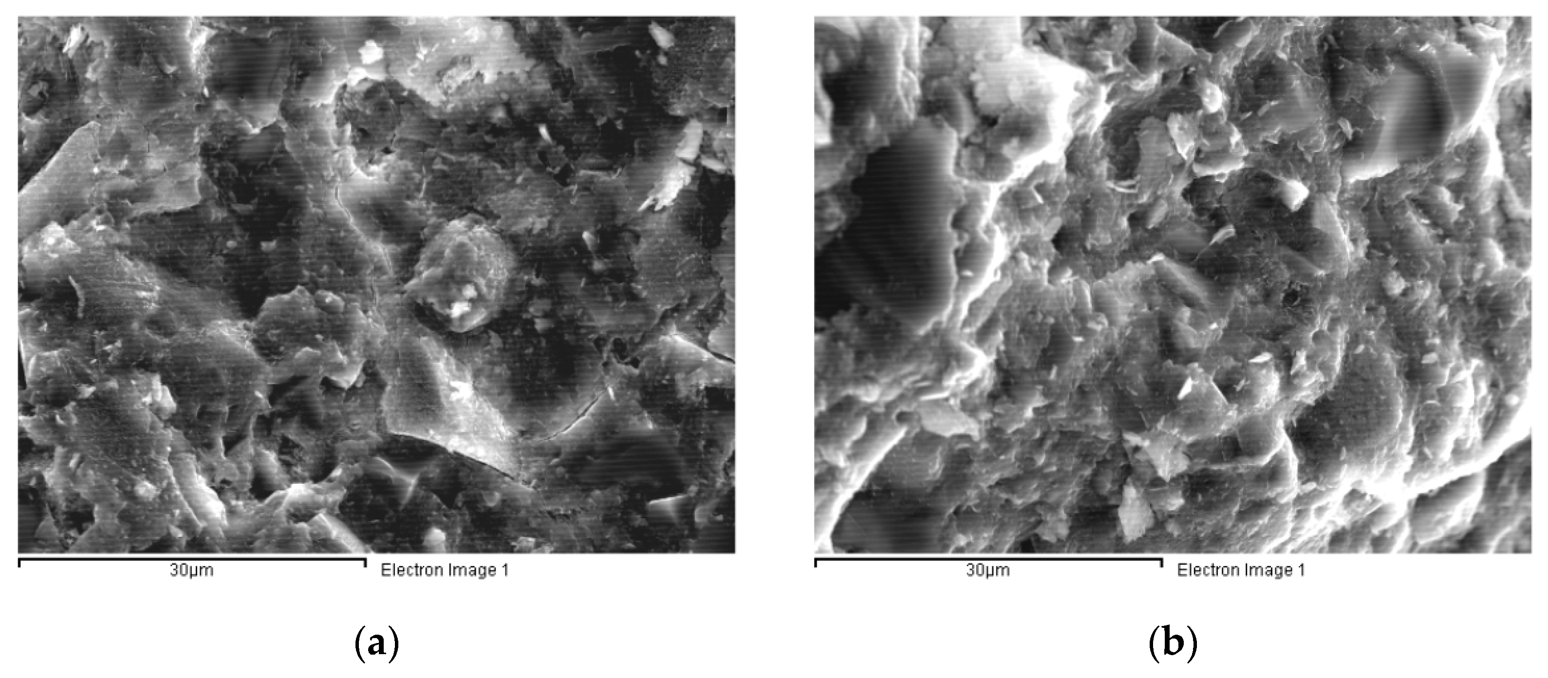
2.2.1. Scanning Electron Microscopy (SEM)
2.2.2. Thermogravimetric Analysis (TGA)
2.2.3. Mercury Intrusion Porosimetry (MIP) Test
2.2.4. Water Absorption Test
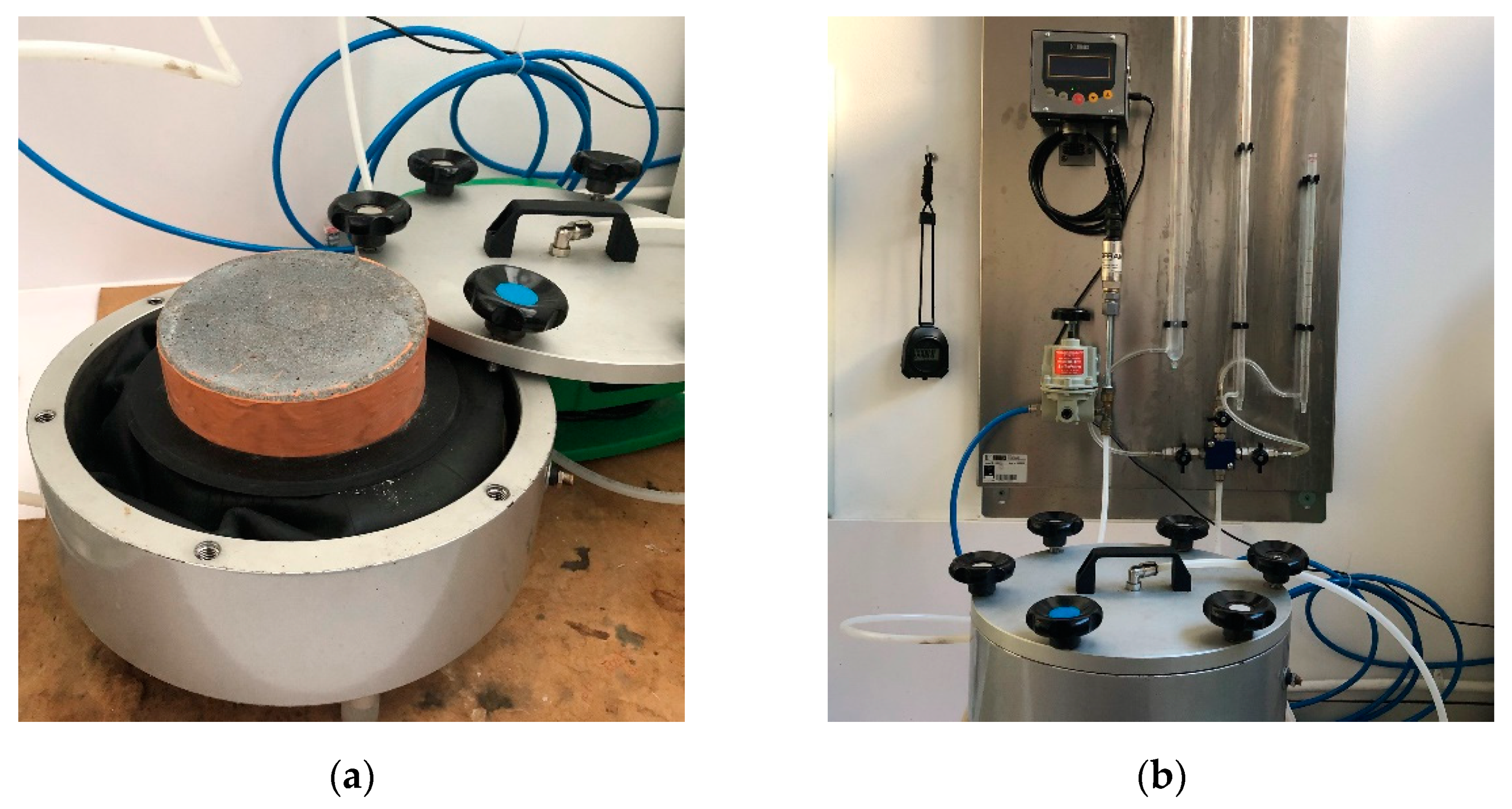
2.2.5. Oxygen Permeability
3. Results
3.1. Microstructure
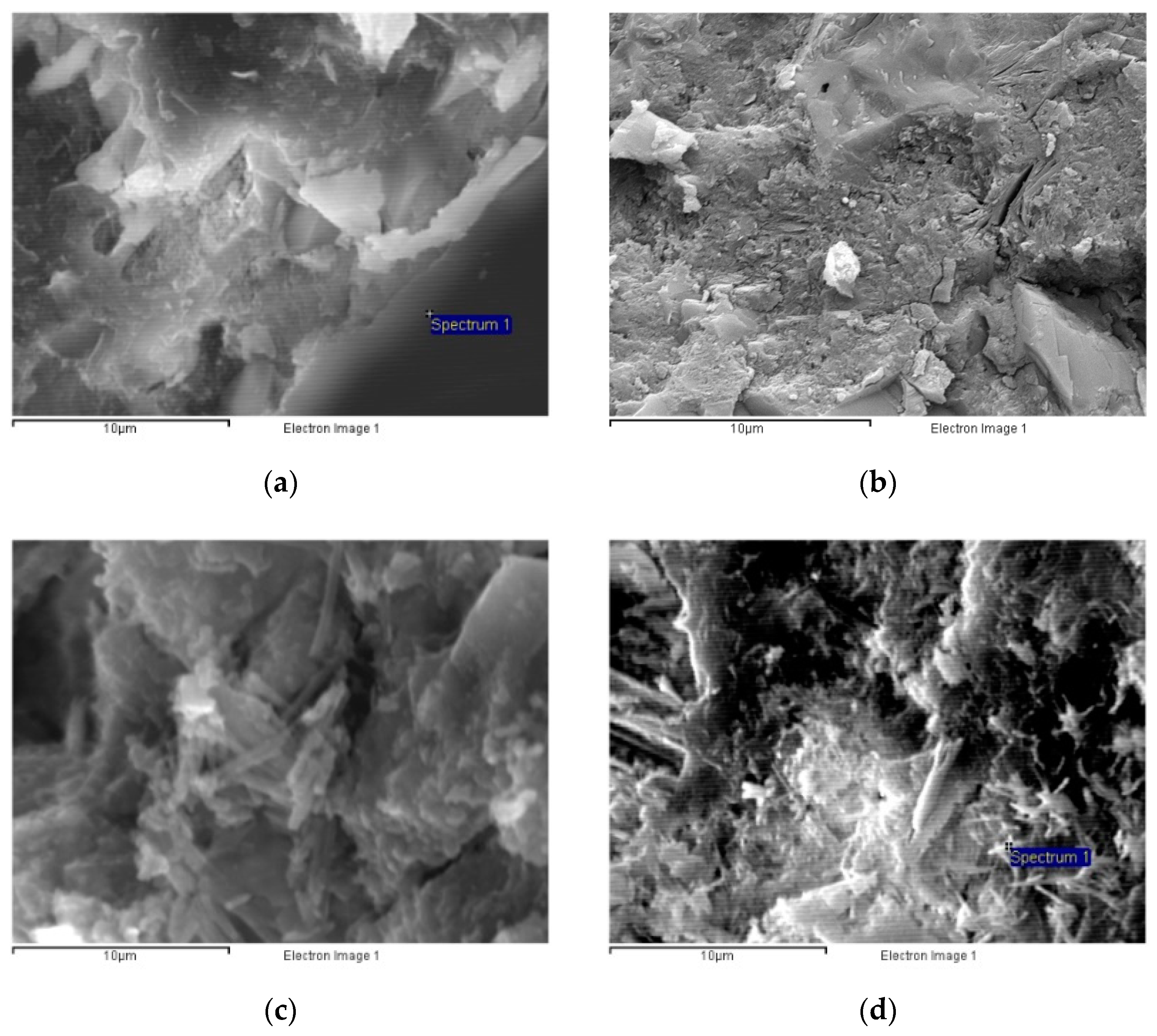
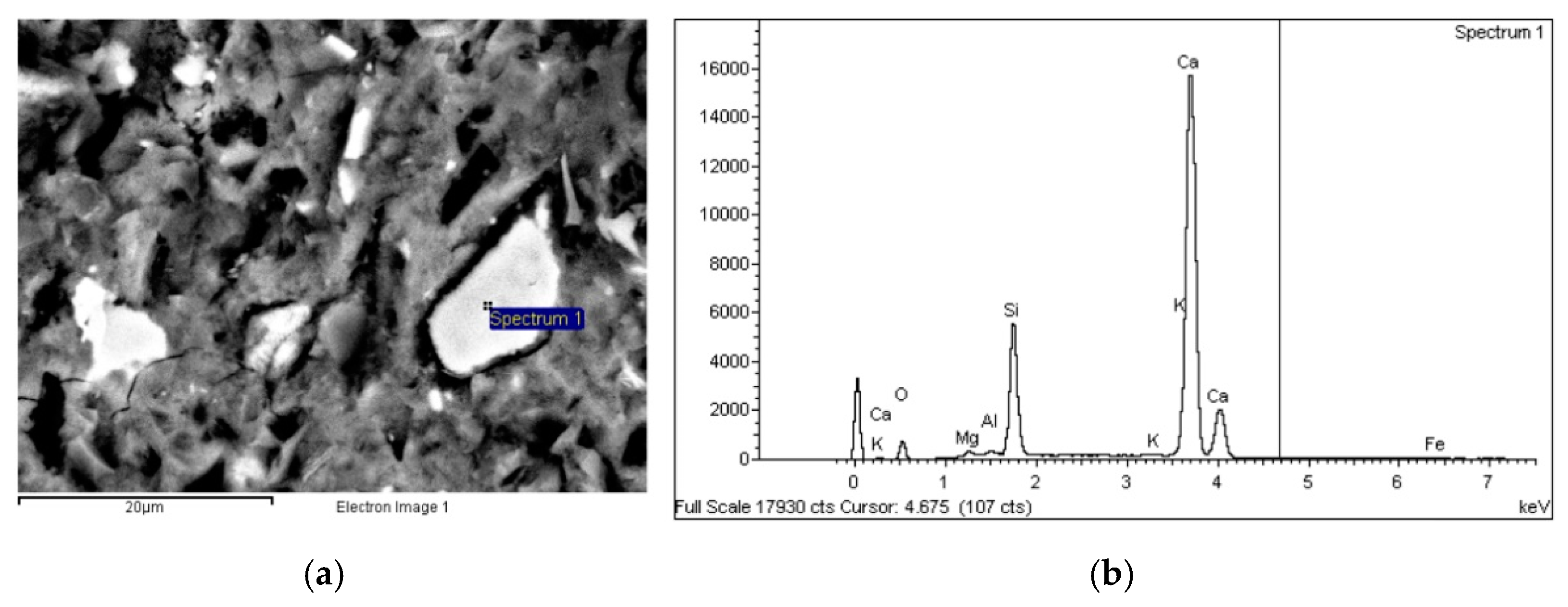
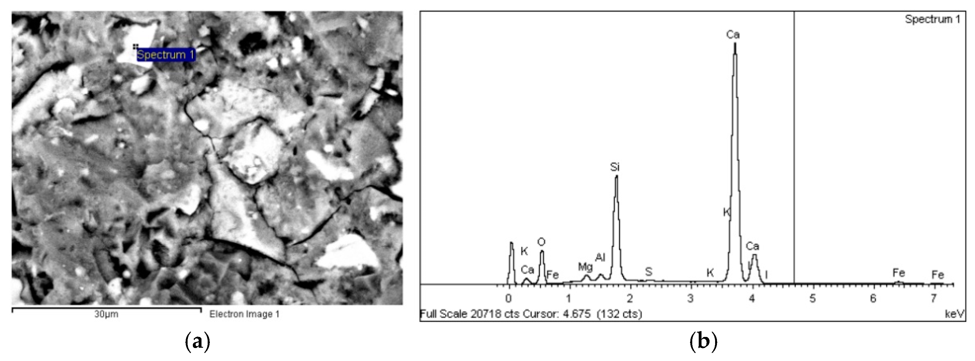
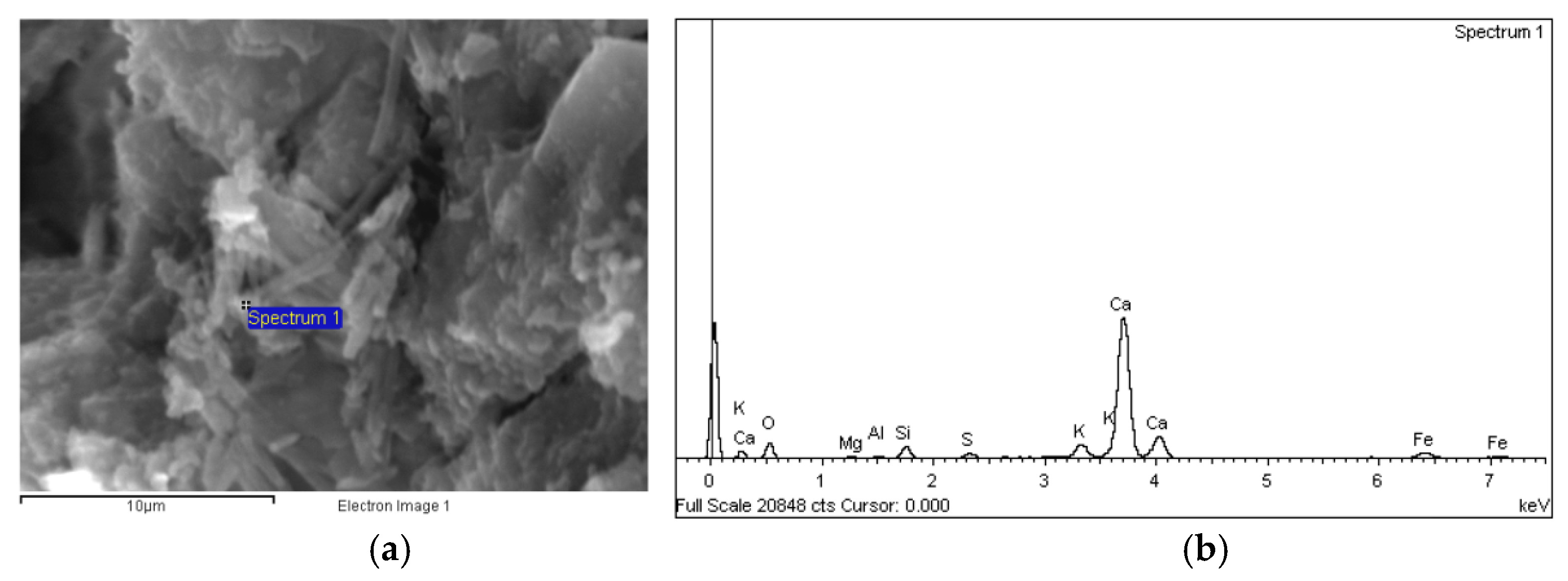
3.1.1. SEM Images
Morphology
Composition
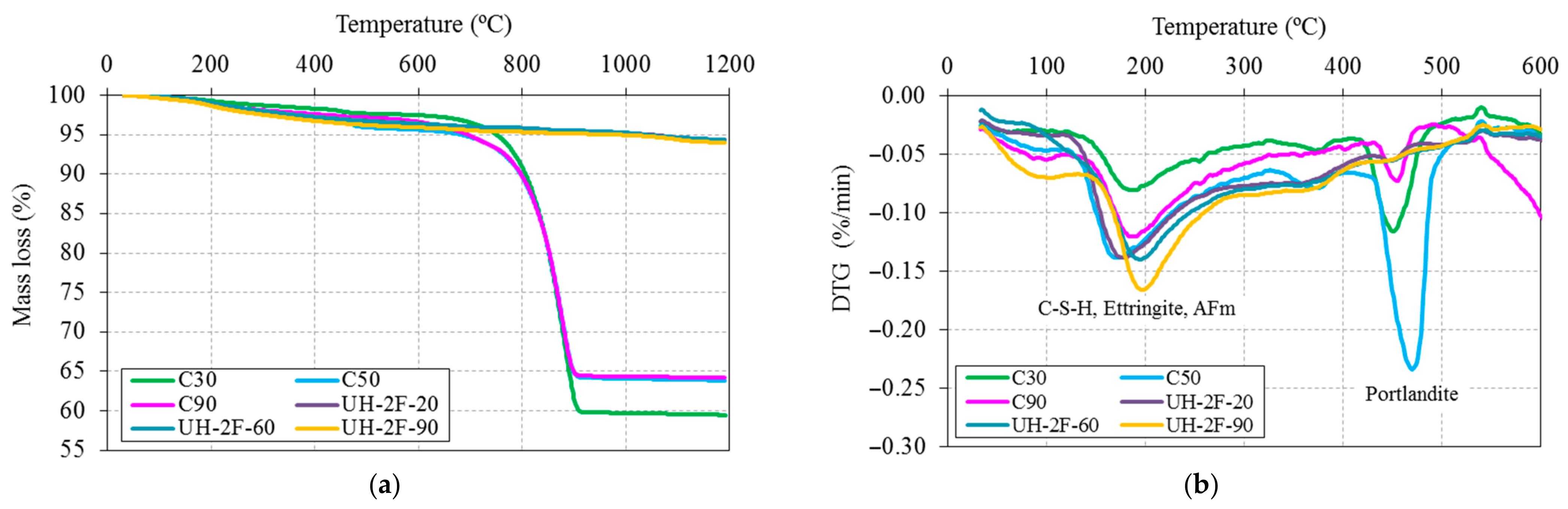
3.1.2. Thermogravimetric Analysis (TGA)
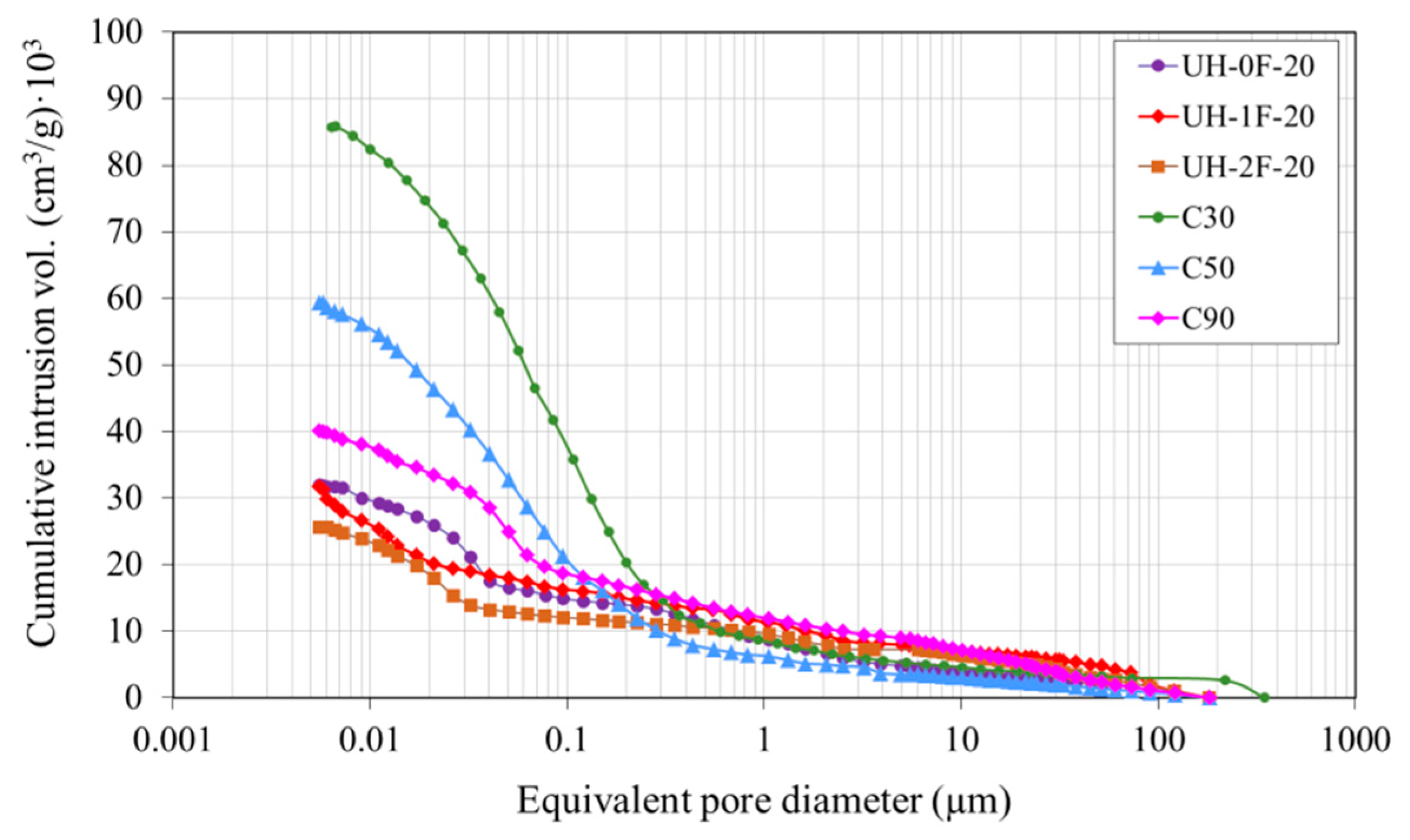
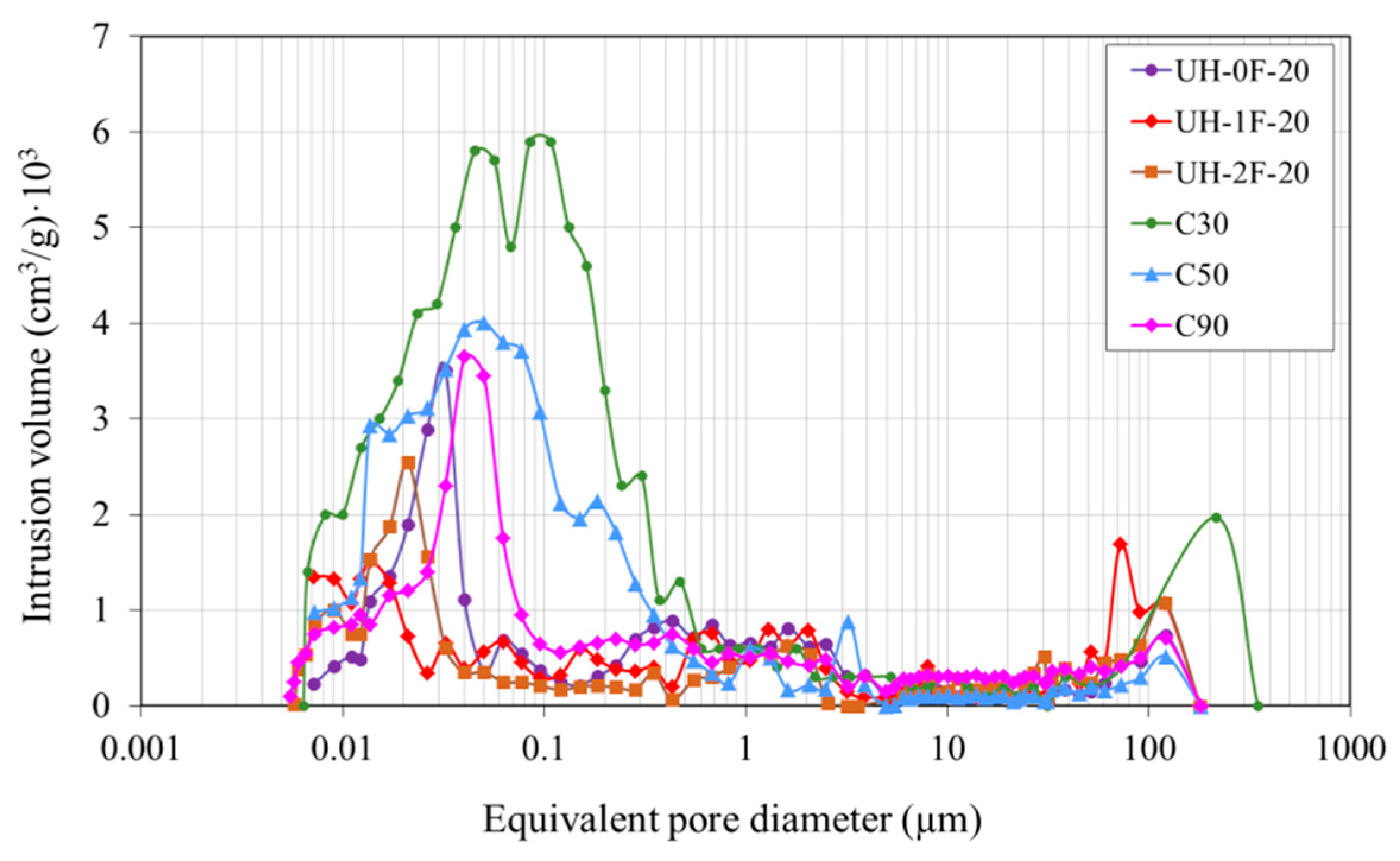
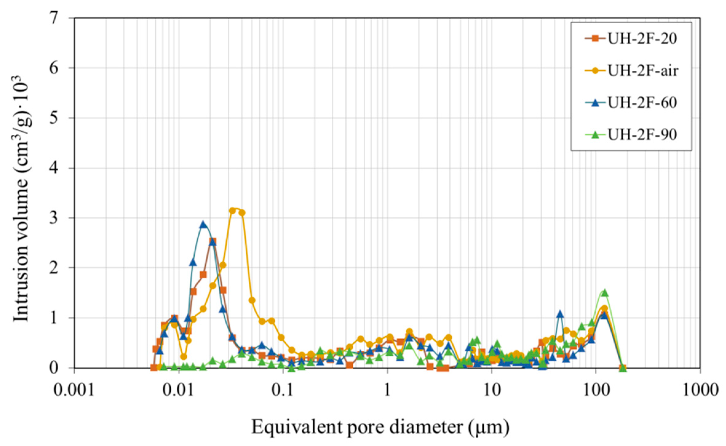
3.1.3. Pore Size Distribution
Effect of Concrete Type
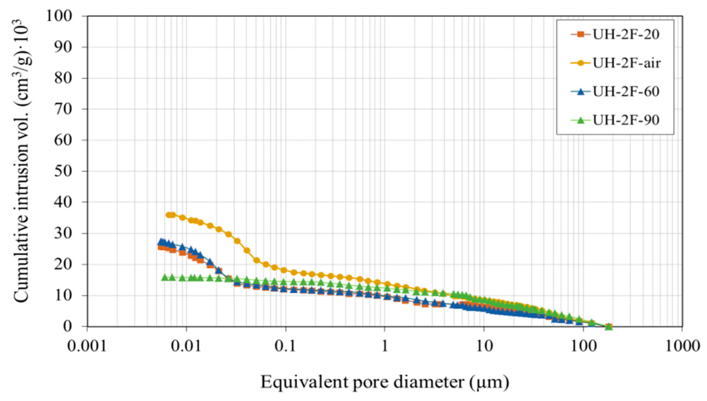
Effect of Curing Conditions on UHs
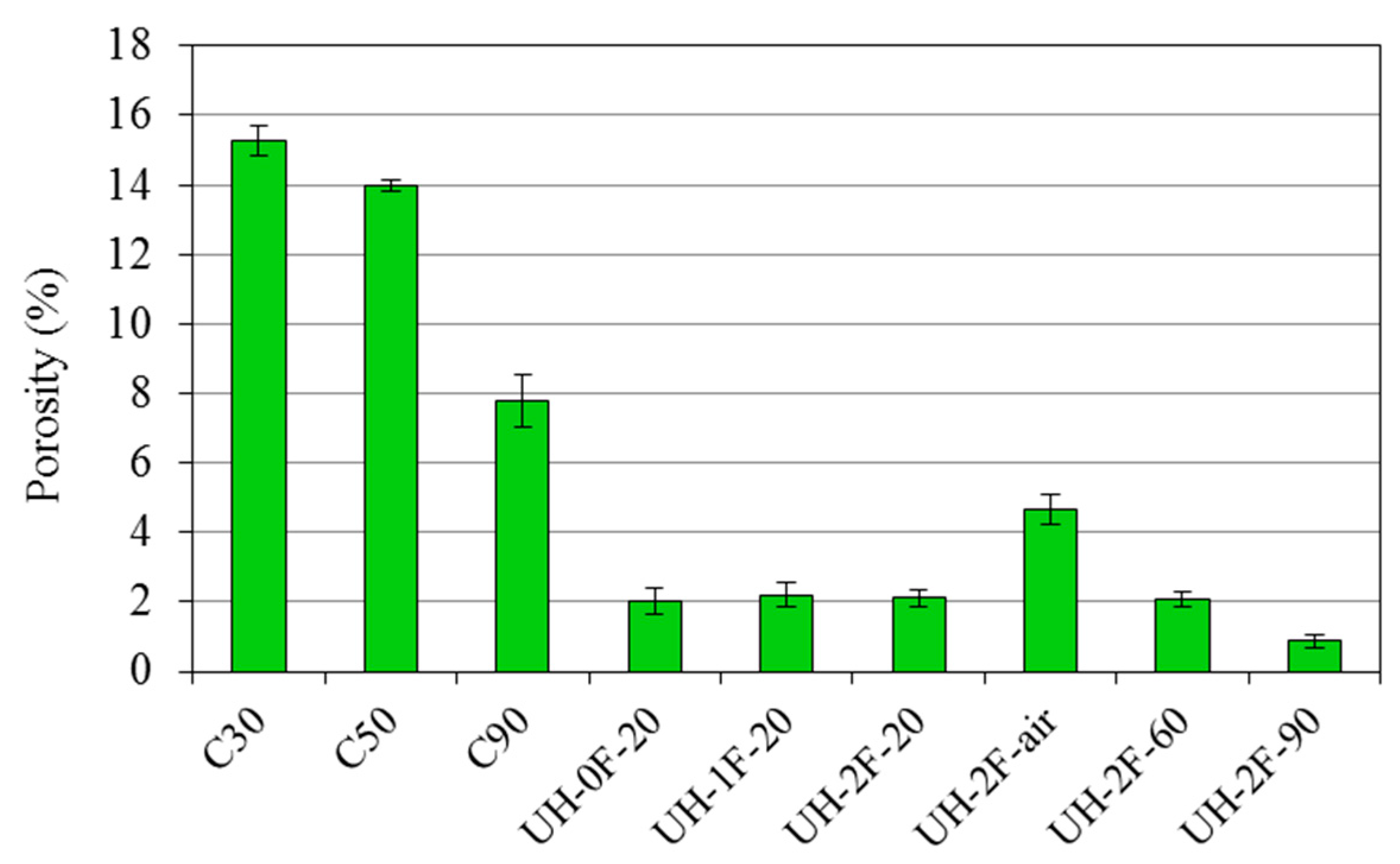
3.2. Porosity Accessible to Water (Water Absorption)
3.2.1. Effect of Concrete Type
3.2.2. Effect of Curing Conditions on UHs
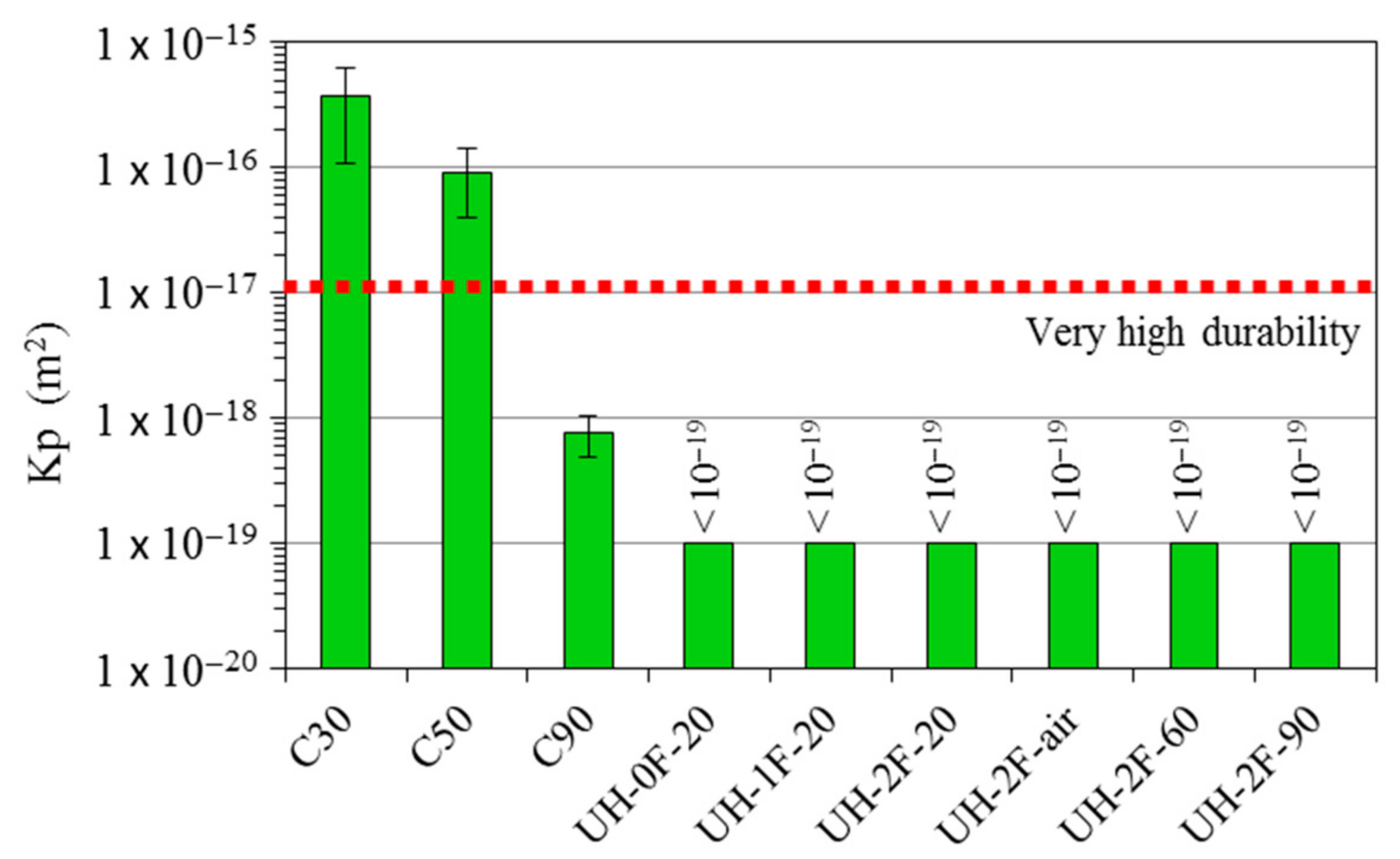
3.3. Oxygen Permeability
4. Discussion
4.1. Effect of Concrete Type
4.2. Effect of Fibre Content
4.3. Effect of Curing Conditions
5. Conclusions
Author Contributions
Funding
Institutional Review Board Statement
Informed Consent Statement
Data Availability Statement
Acknowledgments
Conflicts of Interest
References
- Resplendido, J.; Toutlemonde, F. Designing and Building with UHPFRC. State-of-the-Art and Development; ISTE Ltd. and John Wiley & Sons: London, UK, 2011. [Google Scholar]
- Aïtcin, P.C. Binders for Durable and Sustainable Concrete; Taylor and Francis: London, UK, 2008. [Google Scholar]
- Association Française de Génie Civil (AFGC). Bétons Fibres à Ultra-Hautes Performances; Documents Scientifiques et Techniques; Recommandations: Paris, France, 2013. [Google Scholar]
- SIA. prSIA 2052, Bétón Fibré Ultra-Performant (BFUP): Matériaux, Dimensionnement et Execution; Cahier Technique: Zürich, Switzerland, 2014. [Google Scholar]
- Richard, P.; Cheyrezy, M. Reactive powder concrete with high ductility and 200–800 MPa compressive strength. In Proceedings of the ACI Spring Convention, SP-144, San Francisco, CA, USA, 1 January 1994; pp. 507–508. [Google Scholar]
- De Larrard, F.; Sedran, T. Optimization of ultra-high-performance concrete by the use of a packing model. Cem. Concr. Res. 1994, 24, 997–1009. [Google Scholar] [CrossRef]
- Blais, P.Y.; Couture, M. Precast, Prestressed Pedestrian Bridge—World’s First Reactive Powder Concrete Structure. PCI J. 1999, 60–71. [Google Scholar] [CrossRef]
- Resplendido, J. First recommendations for ultra-high-performance concretes and examples of application. In Proceedings of the International Symposium on Ultra High Performance Concrete, Kessel, Germany, 13–15 September 2004; pp. 79–90. [Google Scholar]
- Ramón, J.E.; Gandía-Romero, J.M.; Bataller, R.; Martínez-Ibernón, A.; Gasch, I.; Soto, J. Integrated sensor network for monitoring Steel corrosion in concrete structures. In Proceedings of the Sixth International Conference on Durability of Concrete Structures (ICDCS2018), Leeds, UK, 1 July 2018; Basheer, P.A.M., Ed.; Whittles Publishing Ltd.: Dunbeath, UK, 2018; pp. 615–619. [Google Scholar]
- Habel, K.; Viviani, M.; Denarié, E.; Brühwiler, E. Development of the mechanical properties of an Ultra-High Performance Fiber Reinforced Concrete (UHPFRC). Cem. Concr. Res. 2006, 36, 1362–1370. [Google Scholar] [CrossRef]
- Graybeal, B.; Tanesi, J. Durability of an Ultrahigh-Performance Concrete. J. Mater. Civ. Eng. 2007, 19, 848–854. [Google Scholar] [CrossRef]
- Ghasemi, S.; Zohrevand, P.; Mirmiran, A.; Xiao, Y.; Mackie, K. A super lightweight UHPC–HSS deck panel for movable bridges. Eng. Struct. 2016, 113, 186–193. [Google Scholar] [CrossRef]
- Heinz, D.; Ludwig, H. Heat treatment and the risk of DEF delayed ettringite formation in UHPC. In Proceedings of the International Symposium on UHPC, Kassel, Germany, 13–15 September 2004; pp. 717–730. [Google Scholar]
- Herold, G.; Muller, H. Measurement of porosity of ultra-high strength fibre reinforced concrete. In Proceedings of the International Symposium on Ultra-High Performance Concrete, Kassel, Germany, 13–15 September 2004; pp. 685–694. [Google Scholar]
- Scheydt, J.C.; Muller, H.S. Microstructure of ultra high performance concrete (UHPC) and its impact on durability. In Proceedings of the 3rd International Symposium on UHPC and Nanotechnology for High Performance Construction Materials, Kassel, Germany, 7–9 March 2012; pp. 349–356. [Google Scholar]
- Khosravania, M.R.; Wagnerb, P.; Fröhlichb, D.; Weinberg, K. Dynamic fracture investigations of ultra-high performance concrete by spalling tests. Eng. Struct. 2019, 201, 109844. [Google Scholar] [CrossRef]
- Yu, R.; Spiesz, P.; Brouwers, H. Mix design and properties assessment of ultrahigh performance fibre reinforced concrete (UHPFRC). Cem. Concr. Res. 2014, 56, 29–39. [Google Scholar] [CrossRef]
- Lampropoulos, A.; Paschalis, S.A.; Tsioulou, O.; Dritsos, S.E. Strengthening of reinforced concrete beams using ultra high performance fibre reinforced concrete (UHPFRC). Eng. Struct. 2016, 106, 370–384. [Google Scholar] [CrossRef]
- Pyo, S.; Kim, H.K. Fresh and hardened properties of ultra-high performance concrete incorporating coal bottom ash and slag powder. Constr. Build. Mater. 2017, 131, 459–466. [Google Scholar] [CrossRef]
- Lu, D.; Zhong, J.; Yan, B.; Gong, J.; He, Z.; Zhang, G.; Song, C. Effects of Curing Conditions on the MECHANICAL and Microstructural Properties of Ultra-High-Performance Concrete (UHPC) Incorporating Iron Tailing Powder. Materials 2021, 14, 215. [Google Scholar] [CrossRef]
- Ghafari, E.; Costa, H.; Júlio, E.; Portugal, A.; Durães, L. The effect of nanosilica addition on flowability, strength and transport properties of ultra high performance concrete. Mater. Des. 2014, 59, 1–9. [Google Scholar] [CrossRef]
- Gesoglu, M.; Güneyisi, E.; Asaad, D.S.; Muhyaddin, G.K. Properties of low binder ultra-high performance cementitious composites: Comparison of nanosilica and microsilica. Constr. Build. Mater. 2016, 102, 706–713. [Google Scholar] [CrossRef]
- Wu, Z.; Shi, C.; Khayat, K.H.; Wan, S. Effects of different nanomaterials on hardening and performance of ultra-high strength concrete (UHSC). Cem. Concr. Compos. 2016, 70, 24–34. [Google Scholar] [CrossRef]
- Jaafar, M.F.; Mohd Saman, H.; Muhd Sidek, M.N.; Ismail, N.; Ariffin, N.F. Chloride Resistance Behavior on Nano-Metaclayed Ultra-High Performance Concrete. In Proceedings of the MATEC Web of Conferences, Malacca, Malaysia, 25–27 February 2017; p. 10301023. [Google Scholar]
- Norhasri, M.S.M.; Hamidah, M.S.; Fadzil, A.M. Inclusion of nano metaclayed as additive in ultra high performance concrete (UHPC). Constr. Build. Mater. 2019, 201, 590–598. [Google Scholar] [CrossRef]
- Kou, S.C.; Xing, F. The effect of recycled glass powder and reject fly ash on the mechanical properties of fibre-reinforced ultra high performance concrete. Adv. Mater. Sci. Eng. 2012, 2012, 263243. [Google Scholar] [CrossRef]
- Vaitkevicius, V.; Šerelis, E.; Vaiciukyniene, D.; Raudonis, V.; Rudzionis, Z. Advanced mechanical properties and frost damage resistance of ultra-high performance fibre reinforced concrete. Constr. Build. Mater. 2016, 126, 26–31. [Google Scholar] [CrossRef]
- Tagnit-Hamou, A.; Soliman, N.; Omran, A. Green Ultra-High-Performance Glass Concrete. In Proceedings of the First International Interactive Symposium on UHPC, Des Moines, IA, USA, 19 July 2016. [Google Scholar] [CrossRef]
- Graybeal, B. Material property characterization of ultrahigh performance concrete. In FHWA-HRT-06-103; U.S. Department of Transportation: Washington, DC, USA, 2006. [Google Scholar]
- Ashour, S.A.; Wafa, F.F.; Kamal, M.I. Effect of the concrete compressive strength and tensile reinforcement ratio on flexural behavior of fibrous concrete. Eng. Struct. 2000, 22, 1145–1158. [Google Scholar] [CrossRef]
- Campione, G.; Mangiavillano, M.L. Fibrous reinforced concrete beams in flexure: Experimental investigation, analytical modelling and design considerations. Eng. Struct. 2008, 30, 2970–2980. [Google Scholar] [CrossRef]
- Prabha, S.L.; Dattatreya, J.K.; Neelamegam, M.; Seshagiri Rao, M.V. Study on stress-strain properties of reactive powder concrete under uniaxial compression. Int. J. Eng. Sci. Technol. 2010, 2, 6408–6416. [Google Scholar]
- Marcalikova, Z.; Cajka, R.; Bilek, V.; Bujdos, D. Sucharda, Determination of Mechanical Characteristics for Fiber-Reinforced Concrete with Straight and Hooked Fibers. Crystals 2020, 10, 545. [Google Scholar] [CrossRef]
- Söylev, T.A.; Özturan, T. Durability, physical and mechanical properties of fiber-reinforced concretes at low-volume fraction. Constr. Build. Mater. 2014, 73, 67–75. [Google Scholar] [CrossRef]
- Yu, R.; Tang, P.; Spiesz, P.; Brouwers, H.J.H. A study of multiple effects of nano-silica and hybrid fibreson the properties of Ultra-High Performance Fibre Reinforced Concrete(UHPFRC) incorporating waste bottom ash (WBA). Constr. Build. Mater. 2014, 60, 98–110. [Google Scholar] [CrossRef]
- Roux, N.; Andrade, C.; Sanjuan, M. Experimental study of durability of reactive powder concretes. J. Mater. Civ. Eng. 1996, 8, 1–6. [Google Scholar] [CrossRef]
- Pierard, J.; Cauberg, N. Evaluation of durability and cracking tendency of ultra-high performance concrete. In Creep, Shrinkage and Durability Mechanics of Concrete and Concrete Structures; Taylor and Francis Group: London, UK, 2009; pp. 695–700. [Google Scholar]
- Ghafari, E.; Bandarabadi, M.; Costa, H.; Julio, E. Design of UHPC using artificial neural networks. In Proceedings of the 10th International Symposium on Brittle Matrix Composites, Warsaw, Poland, 15–17 October 2012; p. 9. [Google Scholar]
- Tam, C.M.; Tam, V.W.Y.; Ng, K.M. Assessing drying shrinkage and water permeability of reactive powder concrete produced in Hong Kong. Constr. Build. Mater. 2012, 26, 79–89. [Google Scholar] [CrossRef]
- Matos, A.M.; Nunes, S.; Costa, C.; Barroso-Aguiar, J.L. Characterization of non-proprietary UHPC for use in rehabilitation/strengthening applications. In Rheology and Processing of Construction Materials; Mechtcherine, V., Khayat, V., Secrieru, E., Eds.; Springer: Cham, Switzerland, 2020; pp. 552–559. [Google Scholar]
- Tafraoui, A.; Escadeillas, G.; Vidal, T. Durability of ultra high performances concrete containing metakaolin. Constr. Build. Mater. 2016, 112, 980–987. [Google Scholar] [CrossRef]
- Yazıcı, H.; Yardımcı, M.Y.; Aydın, S.; Karabulut, A.S. Mechanical properties of reactive powder concrete containing mineral admixtures under different curing regimes. Constr. Build. Mater. 2009, 23, 1223–1231. [Google Scholar] [CrossRef]
- Gu, C.; Sun, W.; Guo, L.; Wang, Q. Effect of curing conditions on the durability of ultra high performance concrete under flexural load. J. Wuhan Univ. Technol. Mater. 2016, 31, 278–285. [Google Scholar] [CrossRef]
- Gesoglu, M.; Guneyisi, E.; Nahhab, A.H.; Yazıcı, H. Properties of ultra-high performance fiber reinforced cementitious composites made with gypsum-contaminated aggregates and cured at normal and elevated temperatures. Constr. Build. Mater. 2015, 93, 427–438. [Google Scholar] [CrossRef]
- Chen, T.; Gao, X.; Ren, M. Effects of autoclave curing and fly ash on mechanical properties of ultra-high performance concrete. Constr. Build. Mater. 2018, 158, 864–872. [Google Scholar] [CrossRef]
- Yoo, D.Y.; Park, J.J.; Kim, S.W.; Yoon, Y.S. Early age setting, shrinkage and tensile characteristics of ultra high performance fiber reinforced concrete. Constr. Build. Mater. 2013, 41, 427–438. [Google Scholar] [CrossRef]
- Song, Q.; Yu, R.; Shui, Z.; Rao, S.; Wang, X.; Sun, M.; Jiang, C. Steel fibre content and interconnection induced electrochemical corrosion of Ultra-High Performance Fibre Reinforced Concrete (UHPFRC). Cem. Concr. Compos. 2018, 94, 191–200. [Google Scholar] [CrossRef]
- Khorami, M.; Navarro-Gregori, J.; Serna, P. Tensile behaviour of reinforced UHPFRC elements under serviceability conditions. Mater. Struct. 2021, 54, 43. [Google Scholar] [CrossRef]
- AENOR. Concrete Durability. Test Methods. Determination of the Water Absorption, Density and Accessible Porosity for Water in Concrete; UNE 83980:2014; Asociación Española de Normalización y Certificación (AENOR): Madrid, Spain, 2014. [Google Scholar]
- AENOR. Concrete Durability. Test Methods. Determination to gas permeability of hardened concrete; UNE 83981:2008; Asociación Española de Normalización y Certificación (AENOR): Madrid, Spain, 2008. [Google Scholar]
- Mounangaa, P.; Khelidja, A.; Loukili, A.; Baroghel-Bouny, V. Predicting Ca(OH)2 content and chemical shrinkage of hydrating cement pastes using analytical approach. Cem. Concr. Res. 2004, 34, 255–265. [Google Scholar] [CrossRef]
- Huang, W.; Kazemi-Kamyab, H.; Sun, W.; Scrivener, K. Effect of replacement of silica fume with calcined clay on the hydration and microstructural development of eco-UHPFRC. Mater. Des. 2017, 121, 36–46. [Google Scholar] [CrossRef]
- Feldman, R.F.; Beaudoin, J.J. Pretreatment of hardened hydrated cement pastes for mercury intrusion measurements. Cem. Concr. Res. 1991, 21, 297–308. [Google Scholar] [CrossRef]
- Payá, J.; Monzó, J.; Borrachero, M.V.; Velázquez, S. Evaluation of the pozzolanic activity of fluid catalytic cracking catalyst residue (FC3R). Thermogravimetric analysis studies on FC3R-Portland cement pastes. Cem. Concr. Res. 2003, 33, 603–609. [Google Scholar] [CrossRef]
- Ollivier, J.P.; Maso, J.C.; Bourdette, B. Interfacial transition zone. Adv. Cem. Based Mater. 1995, 2, 30–38. [Google Scholar] [CrossRef]
- Leemann, A.; Münch, B.; Gasser, P.; Holzer, L. Influence of compaction on the interfacial transition zone and the permeability of concrete. Cem. Concr. Res. 2006, 36, 1425–1433. [Google Scholar] [CrossRef]
- Legrand, C.; Wirkin, E. Study of the strength of very young concrete as a function of the amount of hydrates formed—Influence of superplasticizer. Mater. Struct. 1994, 27, 106–109. [Google Scholar] [CrossRef]
- Li, Z. Drying shrinkage prediction of paste containing meta-kaolin and ultrafine fly ash for developing ultra-high performance concrete. Mater. Today Commun. 2016, 74–80. [Google Scholar] [CrossRef]
- Zhu, Y.; Zhang, Y.; Hussein, H.H.; Liu, J.; Chen, G. Experimental study and theoretical prediction on shrinkage-induced restrained stresses in UHPC-RC composites under normal curing and steam curing. Cem. Concr. Compos. 2020, 110, 103602. [Google Scholar] [CrossRef]
- Baroghel-Bouny, V. Conception des Bétons Pour une Durée de vie Donnée des Ouvrages-Maîtrise de la Durabilité vis-à-vis de la Corrosion des Armatures et de L’alcali-Réaction—Etat de l’art et Guide Pour la Mise en Oeuvre d’une Approche Performantielle et Prédictive sur la Base D’indicateurs de Durabilité; Scientific and Technical Report of the French Civil Engineering Association; AFGC: Bagneux, France, 2004. [Google Scholar]


| UH-0F-20 | UH-1F-20 | UH-2F-20 | UH-2F-air | UH-2F-60 | UH-2F-90 | C30 | C50 | C90 | |
|---|---|---|---|---|---|---|---|---|---|
| Cement | 800 | 800 | 800 | 800 | 800 | 800 | 300 | 450 | 500 |
| Water | 160 | 160 | 160 | 160 | 160 | 160 | 192 | 225 | 178 |
| Superplasticizer | 30 | 30 | 30 | 30 | 30 | 30 | 2.8 | 1.37 | 3.5 |
| Silica fume | 175 | 175 | 175 | 175 | 175 | 175 | --- | --- | 55 |
| Silica flour | 225 | 225 | 225 | 225 | 225 | 225 | --- | --- | --- |
| Sand (0/0.5) | 302 | 302 | 302 | 302 | 302 | 302 | --- | --- | --- |
| Sand (0.6/1.2) | 565 | 565 | 565 | 565 | 565 | 565 | --- | --- | --- |
| Sand (0/4) | --- | --- | --- | --- | --- | --- | 1256 | 880 | 914 |
| Gravel (4/7) | --- | --- | --- | --- | --- | --- | --- | 880 | 779 |
| Gravel (4/12) | --- | --- | --- | --- | --- | --- | 707 | --- | --- |
| Steel fibers | --- | 80 | 160 | 160 | 160 | 160 | --- | --- | --- |
| w/b (*) | 0.19 | 0.19 | 0.19 | 0.19 | 0.19 | 0.19 | 0.65 | 0.50 | 0.33 |
| fc (28 days) | 129.8 (3.71) | 129.9 (3.58) | 128.4 (5.88) | 137.9 (7.26) | 145.7 (6.10) | 154.2 (5.99) | 31.6 (4.40) | 49.9 (3.89) | 88.9 (5.78) |
| C30 | C50 | C90 | UH-2F-20 | UH-2F-60 | UH-2F-90 | |
|---|---|---|---|---|---|---|
| Bound water (110–380 °C) | 0.47 | 0.58 | 0.38 | 0.29 | 0.30 | 0.34 |
| Portlandite (380–520 °C) | 1.09 | 1.37 | 0.49 | 0.36 | 0.41 | 0.41 |
| UH-0F-20 | UH-1F-20 | UH-2F-20 | UH-2F-air | UH-2F-60 | UH-2F-90 | C30 | C50 | C90 | |
|---|---|---|---|---|---|---|---|---|---|
| Volume of pores (cm3/g) | 0.032 | 0.032 | 0.026 | 0.039 | 0.028 | 0.016 | 0.086 | 0.059 | 0.041 |
| Porosity (%) | 7.3 | 7.6 | 6.7 | 9.6 | 6.8 | 4.0 | 17.6 | 13.1 | 10.0 |
| Threshold diameter (μm) | 0.05 | 0.03 | 0.04 | 0.15 | 0.04 | -- | 0.60 | 0.40 | 0.09 |
Publisher’s Note: MDPI stays neutral with regard to jurisdictional claims in published maps and institutional affiliations. |
© 2021 by the authors. Licensee MDPI, Basel, Switzerland. This article is an open access article distributed under the terms and conditions of the Creative Commons Attribution (CC BY) license (http://creativecommons.org/licenses/by/4.0/).
Share and Cite
Valcuende, M.; Lliso-Ferrando, J.R.; Roig-Flores, M.; Gandía-Romero, J.M. Porous Structure of Ultra-High-Performance Fibre-Reinforced Concretes. Materials 2021, 14, 1637. https://doi.org/10.3390/ma14071637
Valcuende M, Lliso-Ferrando JR, Roig-Flores M, Gandía-Romero JM. Porous Structure of Ultra-High-Performance Fibre-Reinforced Concretes. Materials. 2021; 14(7):1637. https://doi.org/10.3390/ma14071637
Chicago/Turabian StyleValcuende, Manuel, Josep R. Lliso-Ferrando, Marta Roig-Flores, and José M. Gandía-Romero. 2021. "Porous Structure of Ultra-High-Performance Fibre-Reinforced Concretes" Materials 14, no. 7: 1637. https://doi.org/10.3390/ma14071637
APA StyleValcuende, M., Lliso-Ferrando, J. R., Roig-Flores, M., & Gandía-Romero, J. M. (2021). Porous Structure of Ultra-High-Performance Fibre-Reinforced Concretes. Materials, 14(7), 1637. https://doi.org/10.3390/ma14071637