
Mechanical and Thermal Properties of Polyurethane Materials and Inflated Insulation Chambers


Abstract
:1. Introduction
- Parameters of the body: skin wetness (w), skin temperature (tsk), DuBois area (ADu), the part of skin included in the transfer by radiation (Ar/ADu), and skin emissivity (εsk);
- Parameters of the environment: radiant temperature (tr), air velocity (v), air temperature (ta), air pressure (pa), and pressure on the skin (psk,s);
- Parameters of textile/clothing: clothing insulation (Icl), clothing area factor (fcl), and clothing temperature (tcl).
2. Research Methodology
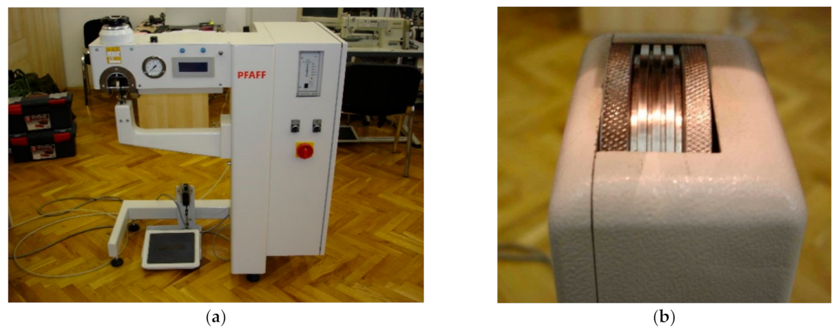
2.1. Materials and Joining Technique
2.2. Measurement of Mechanical Properties of Polyurethane Materials
2.3. Design of PICs
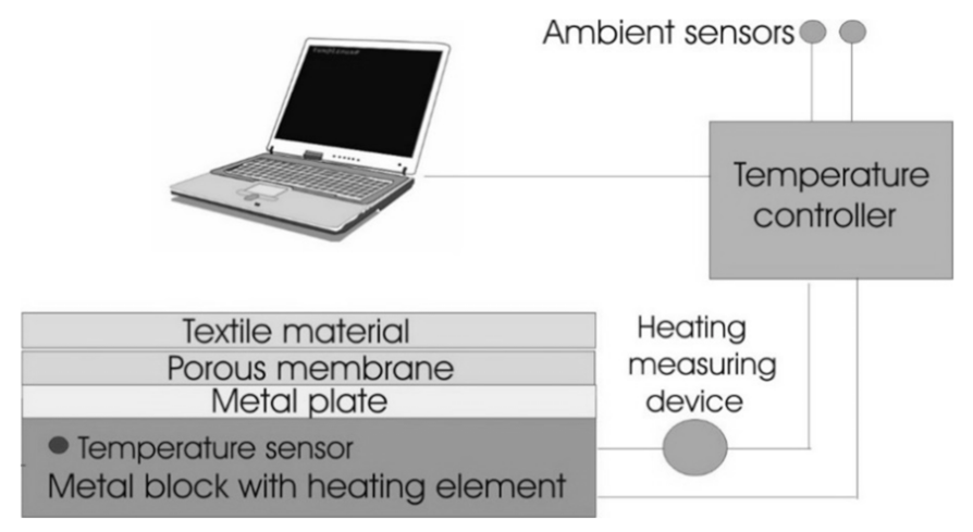
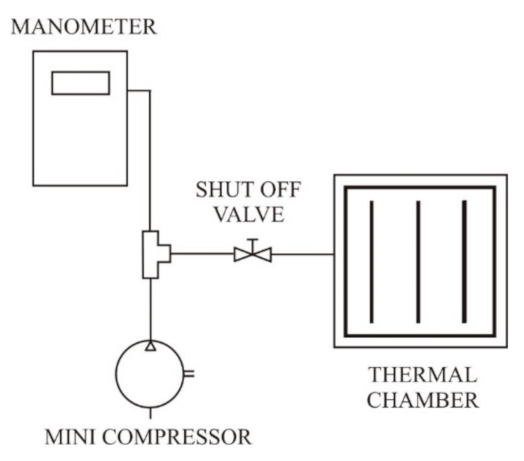
2.4. Measurement of Thermal Properties of PICs
3. Results and Discussion
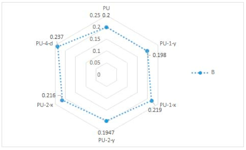
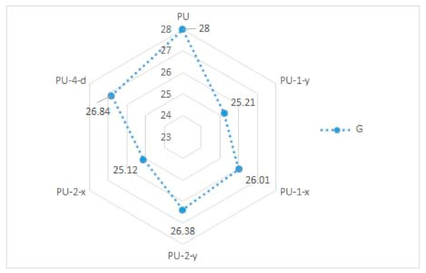
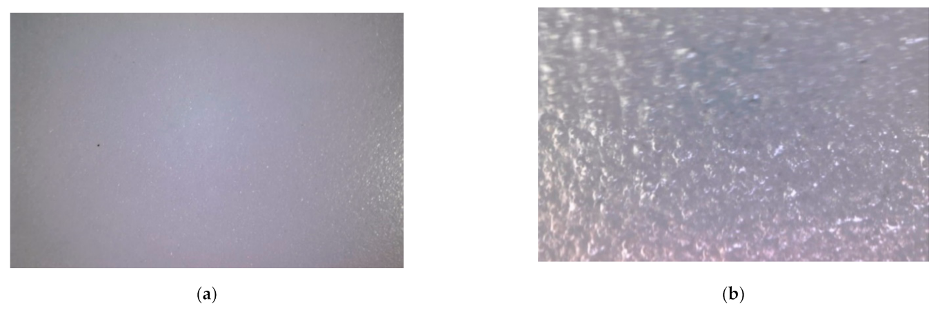
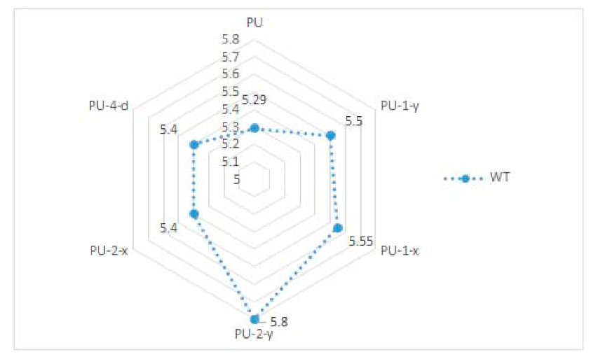
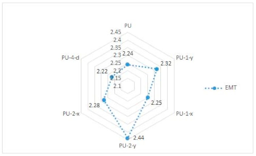
3.1. Measured Mechanical Properties of Polyurethane Materials
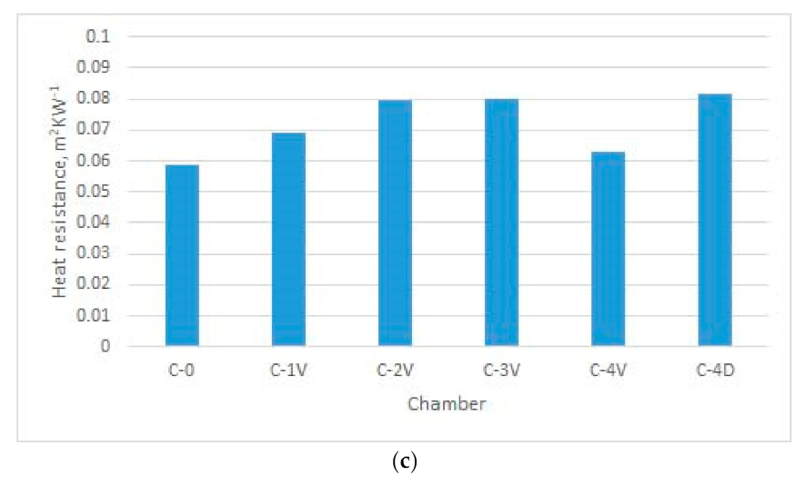
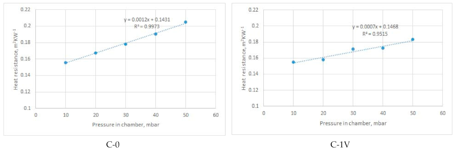
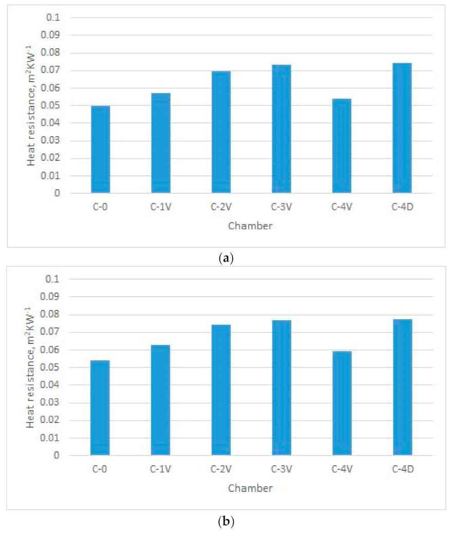
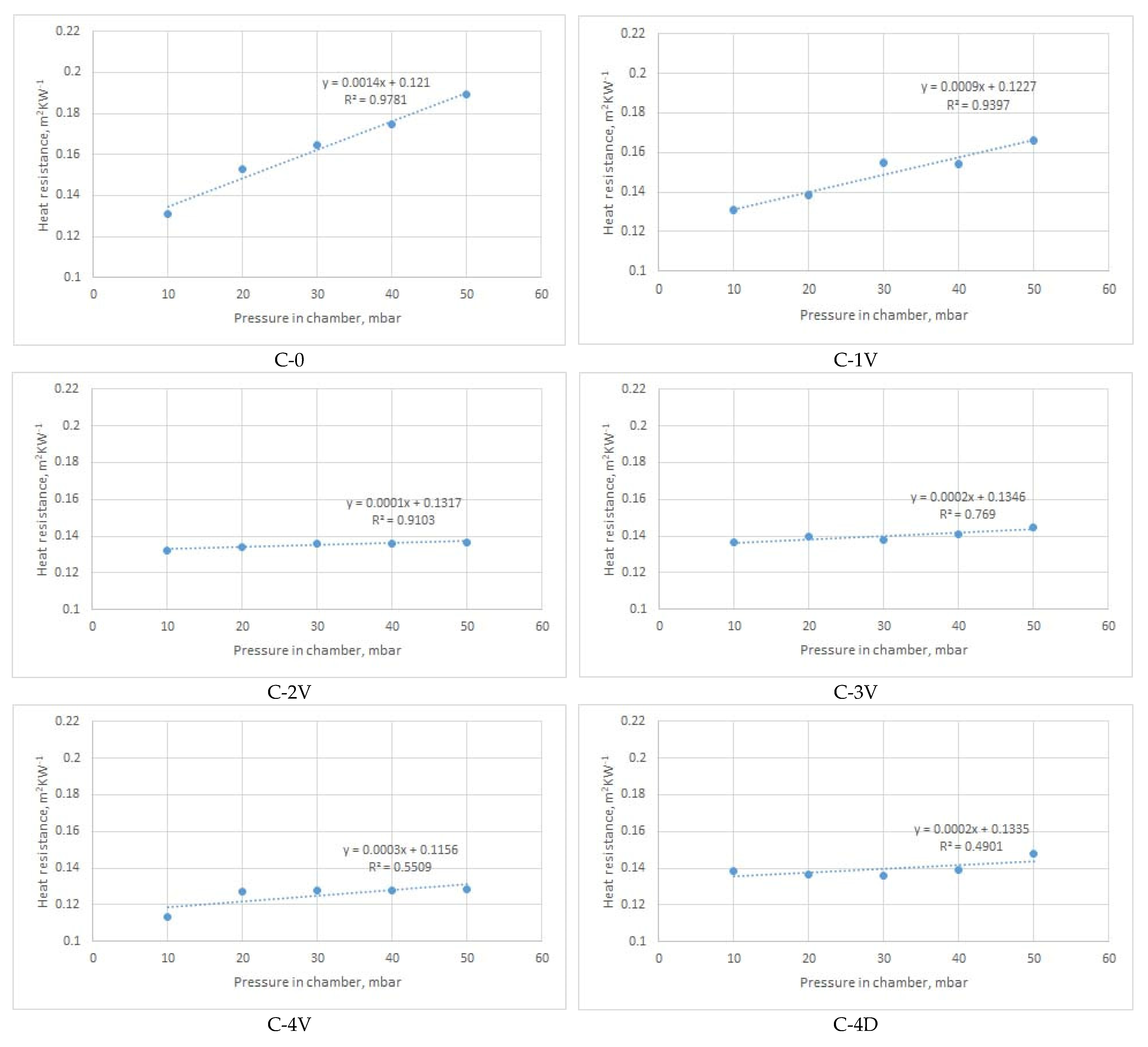
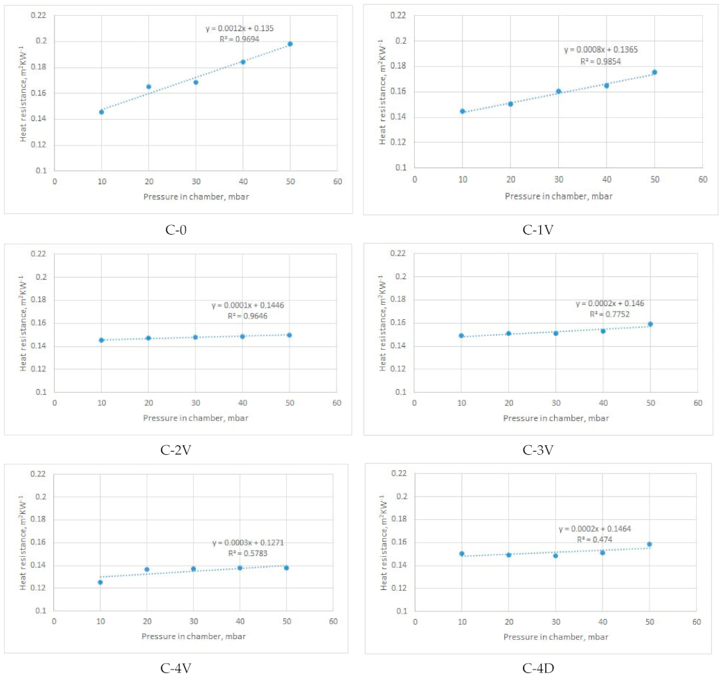
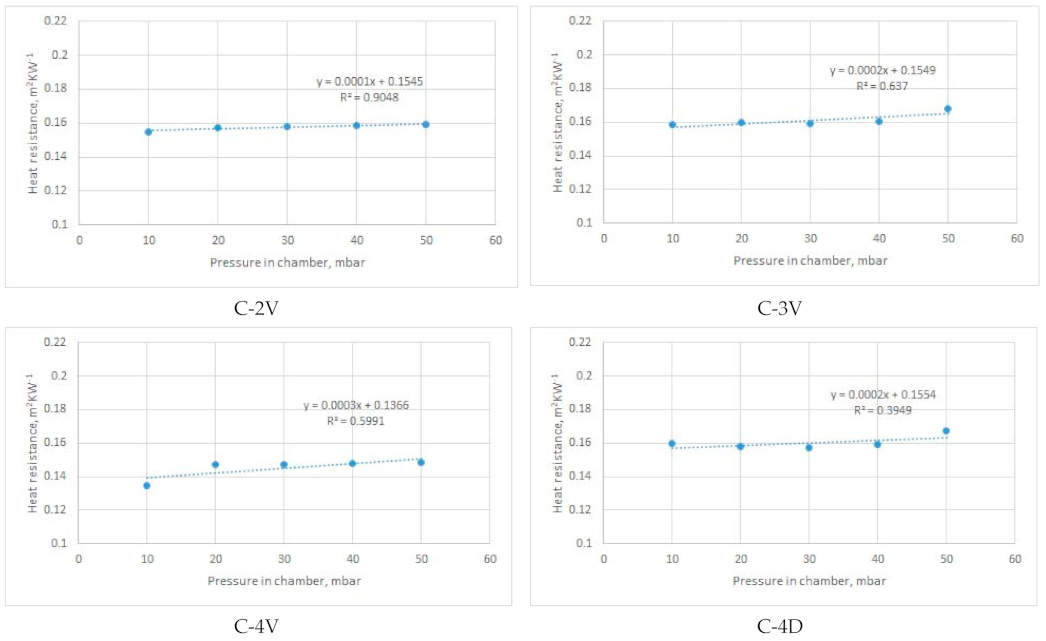
3.2. Measured Thermal Properties of PICs
- -
- for T = 20 °C: CV = 0.12–1.12%;
- -
- for T = 15 °C: CV = 0.15–1.13%;
- -
- for T = 10 °C: CV = 0.12–1.56%.
4. Conclusions
Author Contributions
Funding
Institutional Review Board Statement
Informed Consent Statement
Data Availability Statement
Conflicts of Interest
References
- Tunakova, V.; Tunak, M.; Tesinova, P.; Seidlova, M.; Prochazka, J. Fashion clothing with electromagnetic radiation protection: Aesthetic properties and performance. Text. Res. J. 2020, 90, 2504–2521. [Google Scholar] [CrossRef]
- Li, R.; Yang, J.; Xiang, C.; Song, G. Assessment of thermal comfort of nanosilver-treated functional sportswear fabrics using a dynamic thermal model with human/clothing/environmental factors. Text. Res. J. 2018, 88, 413–425. [Google Scholar] [CrossRef]
- Wardiningsih, W.; Troynikov, O. Treated knitted fabric for hip protective pads for elderly women. Part II. Performance relevant to thermal comfort. Text. Res. J. 2019, 89, 5006–5013. [Google Scholar] [CrossRef]
- Atasağun, H.G.; Okur, A.; Psikuta, A.; Rossi, R.M.; Annaheim, S. The effect of garment combinations on thermal comfort of office clothing. Text. Res. J. 2019, 89, 4425–4437. [Google Scholar] [CrossRef]
- Erdumlu, N.; Saricam, C. Investigating the effect of some fabric parameters on the thermal comfort properties of flat knitted acrylic fabrics for winter wear. Text. Res. J. 2017, 87, 1349–1359. [Google Scholar] [CrossRef]
- Uren, N.; Okur, A. Analysis and improvement of tactile comfort and low-stress mechanical properties of denim fabrics. Text. Res. J. 2019, 89, 4842–4857. [Google Scholar] [CrossRef]
- Salopek Cubric, I.; Skenderi, Z. Evaluating Thermophysiological Comfort Using the Principles of Sensory Analysis. Coll. Antropol. 2013, 37, 57–64. [Google Scholar]
- Balci Kilic, G.; Okur, A. Effect of yarn characteristics on surface properties of knitted fabrics. Text. Res. J. 2019, 89, 2476–2489. [Google Scholar] [CrossRef]
- Salopek Čubrić, I.; Čubrić, G.; Perry, P. Assessment of Knitted Fabric Smoothness and Softness Based on Paired Comparison. Fibers Polym. 2019, 20, 656–667. [Google Scholar] [CrossRef]
- Fan, J.; Tsang, H.W.K. Effect of Clothing Thermal Properties on the Thermal Comfort Sensation during Active Sports. Text. Res. J. 2008, 78, 111–118. [Google Scholar]
- Wang, S.X.; Li, Y.; Tokura, H.; Hu, J.Y.; Han, Y.X.; Kwok, Y.L.; Au, R.W. Effect of Moisture Management on Functional Performance of Cold Protective Clothing. Text. Res. J. 2007, 77, 968–980. [Google Scholar] [CrossRef]
- Kofler, P.; Nussbichler, M.; Veider, V.; Khanna, I.; Heinrich, D.; Bottoni, G.; Hasler, M.; Caven, B.; Bechtold, T.; Burtscher, M.; et al. Effects of two different battings (sheep wool versus polyester microfiber) in an outdoor jacket on the heat and moisture management and comfort sensation in the cold. Text. Res. J. 2016, 86, 191–201. [Google Scholar] [CrossRef]
- Angelova, R.A.; Reiners, P.; Georgieva, E.; Kyosev, Y. The effect of the transfer abilities of single layers on the heat and mass transport through multilayered outerwear clothing for cold protection. Text. Res. J. 2018, 88, 1125–1137. [Google Scholar] [CrossRef]
- Salopek Čubrić, I.; Skenderi, Z. Effect of Finishing Treatments on Heat Resistance of One- and Two- Layered Fabrics. Fibers Polym. 2014, 15, 1635–1640. [Google Scholar] [CrossRef]
- He, J.; Li, J.; Kim, E. Assessment of the heat and moisture transfer in a multilayer protective fabric system under various ambient conditions. Text. Res. J. 2015, 85, 227–237. [Google Scholar] [CrossRef]
- Firšt Rogale, S.; Rogale, D.; Nikolić, G. Intelligent clothing: First and second generation clothing with adaptive thermal insulation properties. Text. Res. J. 2018, 88, 2214–2233. [Google Scholar] [CrossRef]
- Rogale, D.; Firšt Rogale, S.; Majstorović, G.; Čubrić, G. Thermal properties of thermal insulation chambers. Text. Res. J. 2020. [Google Scholar] [CrossRef]
- Potočić Matković, V.M.; Salopek Čubrić, I.; Skenderi, Z. Thermal resistance of polyurethane-coated knitted fabrics before and after weathering. Text. Res. J. 2014, 84, 2015–2025. [Google Scholar] [CrossRef]
- Firšt Rogale, S.; Rogale, D.; Nikolić, G.; Dragčević, Z.; Bartoš, M. Controllable Ribbed Thermoinsulative Chamber of Continually Adjustable Thickness and Its Application; EP2254430; European Patent Office (EPO): Munich, Germany, 2010. [Google Scholar]
- Čubrić, G.; Geršak, J.; Rogale, D.; Nikolić, G. Determination of mechanical properties of ultrasonically bonded polyurethane foils. Tekstil 2009, 58, 485–492. [Google Scholar]
- Salopek, I.; Skenderi, Z.; Gersak, J. Investigation of knitted fabric dimensional characteristics. Tekstil 2007, 56, 391–398. [Google Scholar]
- Mijović, B.; Skenderi, Z.; Salopek, I. Comparison of Subjective and Objective Measurement of Sweat Transfer Rate. Coll. Antropol. 2009, 33, 509–514. [Google Scholar] [PubMed]
- Textiles—Physiological effects—Measurement of Thermal and Water-Vapour Resistance under Steady-State Conditions (Sweating Guarded-Hotplate Test); ISO 11092:2014; International Organization for Standardization: Geneva, Switzerland, 2014.


| No. | PIC ID | Dimension | Description |
|---|---|---|---|
| 1 | C-0 | 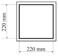 | - joint type: ultrasonic - number of joints: 0 - position of joints: n/a - length of joint: n/a |
| 2 | C-1V |  | - joint type: ultrasonic - number of joints: 1 - position of joints: in the middle - length of joint: 180 mm |
| 3 | C-2V | 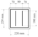 | - joint type: ultrasonic - number of joints: 2 - position of joints: two joints with a spacing of 80 mm - length of joint: 180 mm |
| 4 | C-3V |  | - joint type: ultrasonic - number of joints: 3 - position of joints: three joints with a spacing of 70 mm - length of joint: 180 mm |
| 5 | C-4V | 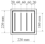 | - joint type: ultrasonic - number of joints: 4 - position of joints: four joints with a spacing of 60 mm - length of joint: 180 mm |
| 6 | C-4D | 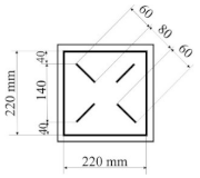 | - joint type: ultrasonic - number of joints: 4 - position of joints: diagonal with break - length of joint: 60 mm |
| Property | Index | Average Value | Coefficient of Variation, % |
|---|---|---|---|
| Compressional energy, N·m−1 | WC | 0.046 | 13.50 |
| Compressional resilience, % | RC | 81.02 | 11.13 |
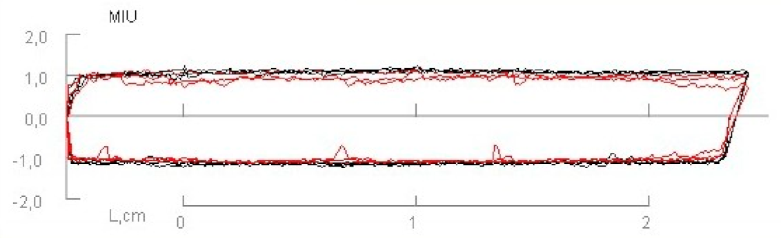
| Coefficient of friction, dimensionless | MIU | 1.064 | 5.71 |
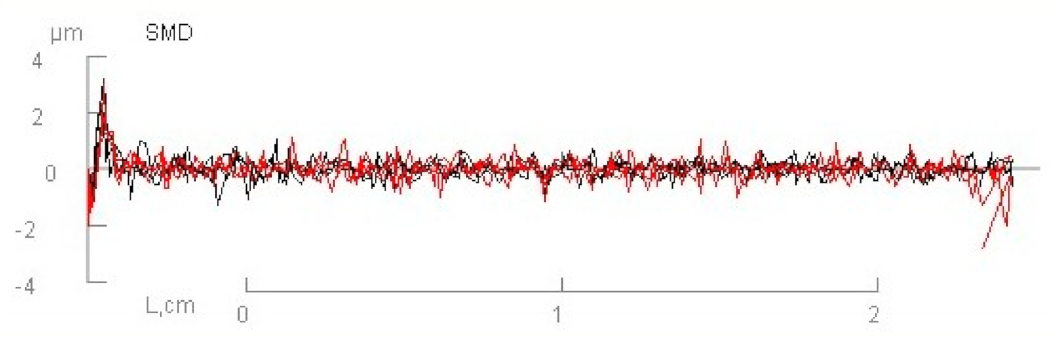
| Surface roughness, μm | SMD | 0.221 | 3.43 |
| Ambient Temperature | |||
|---|---|---|---|
| PIC ID | 20 °C | 15 °C | 10 °C |
| C-0 | 3.82 | 3.67 | 3.47 |
| C-1V | 2.90 | 2.78 | 2.65 |
| C-2V | 1.92 | 2.01 | 1.99 |
| C-3V | 1.97 | 2.00 | 2.09 |
| C-4V | 2.06 | 2.03 | 2.06 |
| C-4D | 1.99 | 2.04 | 2.05 |
Publisher’s Note: MDPI stays neutral with regard to jurisdictional claims in published maps and institutional affiliations. |
© 2021 by the authors. Licensee MDPI, Basel, Switzerland. This article is an open access article distributed under the terms and conditions of the Creative Commons Attribution (CC BY) license (http://creativecommons.org/licenses/by/4.0/).
Share and Cite
Čubrić, G.; Salopek Čubrić, I.; Rogale, D.; Firšt Rogale, S. Mechanical and Thermal Properties of Polyurethane Materials and Inflated Insulation Chambers. Materials 2021, 14, 1541. https://doi.org/10.3390/ma14061541
Čubrić G, Salopek Čubrić I, Rogale D, Firšt Rogale S. Mechanical and Thermal Properties of Polyurethane Materials and Inflated Insulation Chambers. Materials. 2021; 14(6):1541. https://doi.org/10.3390/ma14061541
Chicago/Turabian StyleČubrić, Goran, Ivana Salopek Čubrić, Dubravko Rogale, and Snježana Firšt Rogale. 2021. "Mechanical and Thermal Properties of Polyurethane Materials and Inflated Insulation Chambers" Materials 14, no. 6: 1541. https://doi.org/10.3390/ma14061541
APA StyleČubrić, G., Salopek Čubrić, I., Rogale, D., & Firšt Rogale, S. (2021). Mechanical and Thermal Properties of Polyurethane Materials and Inflated Insulation Chambers. Materials, 14(6), 1541. https://doi.org/10.3390/ma14061541