
Optimizing 3D Printed Metallic Object’s Postprocessing: A Case of Gamma-TiAl Alloys


Abstract
1. Introduction
- more complex and unique geometries (internal channels and cavities) can be produced by EBM [13],
- the cost of expensive tooling (dies and molds) can be eliminated,
- oxidation- and impurity-free parts can be achieved since the process is accomplished in a vacuum [12], and
- uniform microstructures can be maintained while printing the part [14].
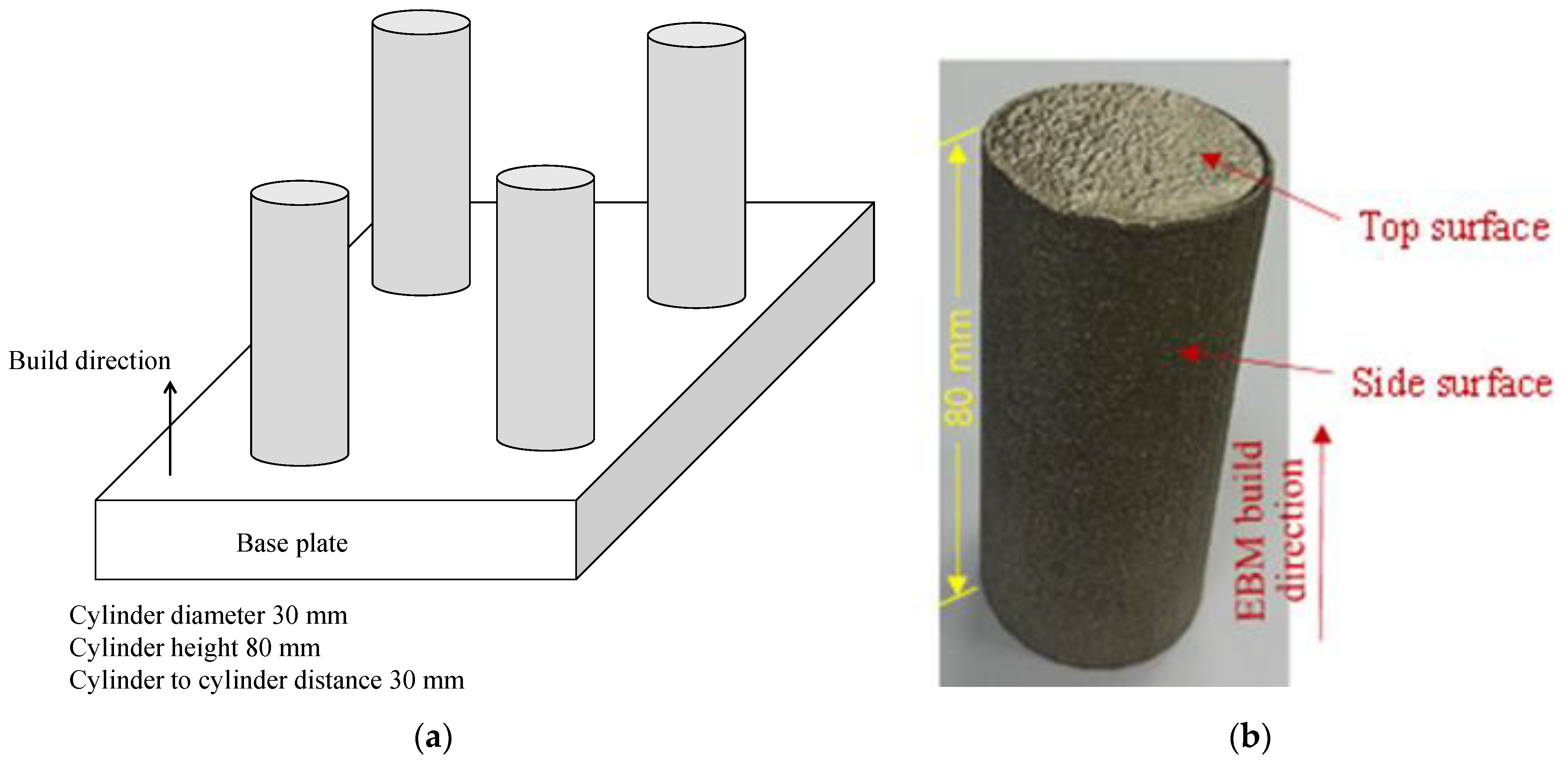
2. Experimentation
3. Optimization
4. Concluding Remarks
- Gamma-TiAl alloys fabricated by Electron Beam Melting (an additive manufacturing process) can replace Ti6Al4V and other similar alloys in high-end aerospace and biomedical applications.
- Since additively fabricated objects made of Gamma-TiAl alloys exhibit poor surface finish, they must be post-processed by traditional manufacturing processes. In this study, turning is utilized as a postprocessing method for EBM-produced Gamma-TiAl. It can be mentioned here that the minimum surface roughness Ra = 0.18 was achieved for the input parameter set of nose radius = 0.8 mm, cutting speed = 80 m/min, depth of cut = 0.1 mm, feed rate = 0.05 mm/rev, and coolant flow rate = 2 L/min. This Ra value is within the applicable level for medical implants [43].
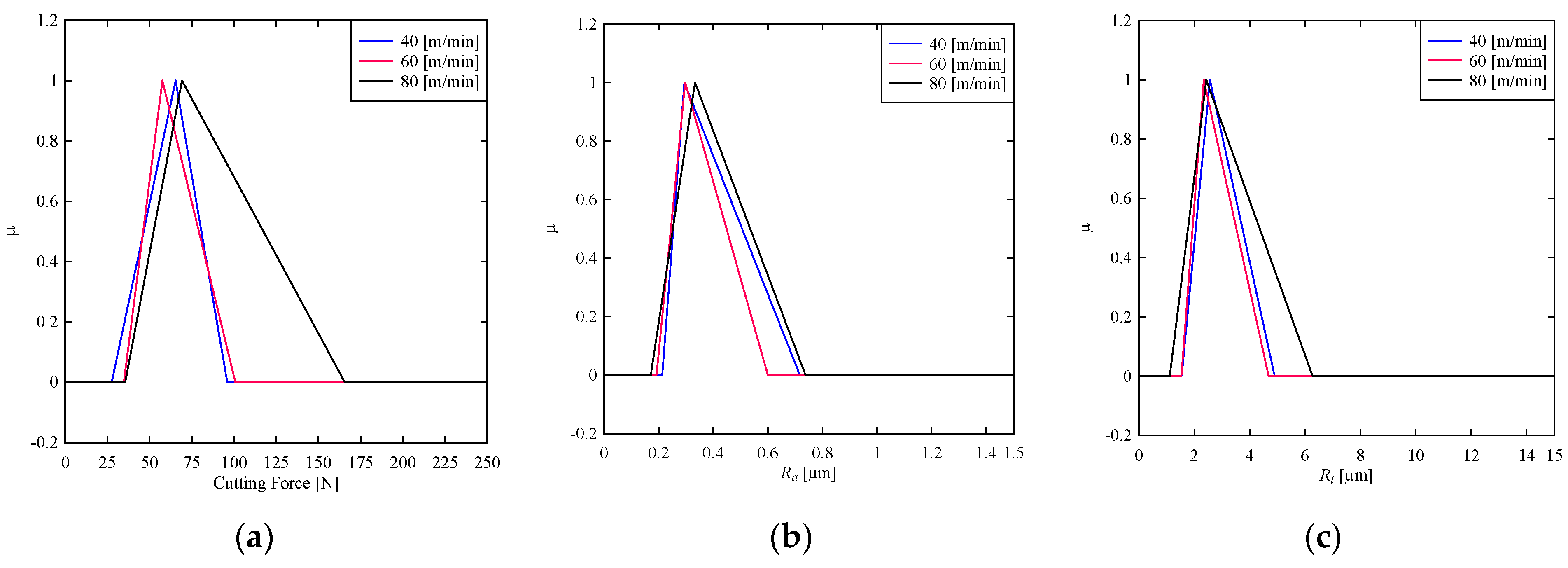
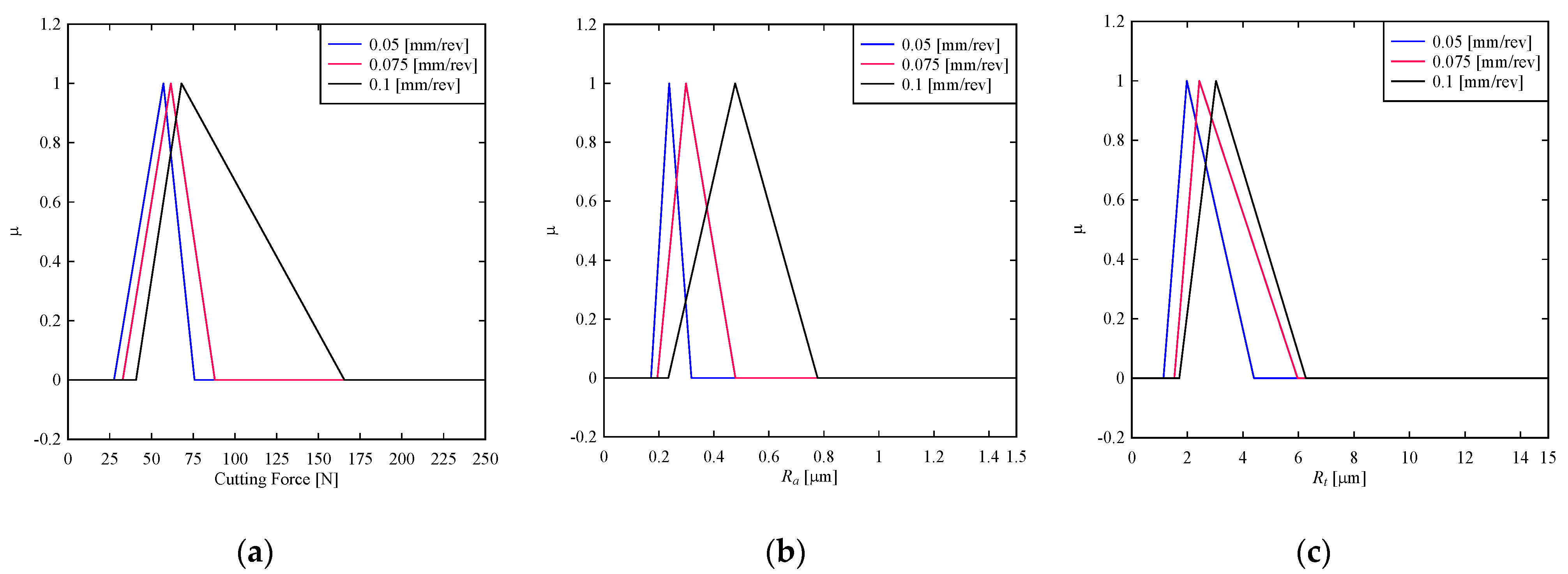
- While postprocessing additively manufactured specimens made of Gamma-TiAl alloys using turning, the following optimal cutting conditions can be used: coolant flow rate of 8 L/min (high coolant flowrate), nose radius of 0.8 mm (high nose radius), cutting speed of 60 m/min (moderate cutting speed), depth of cut of 0.1 mm (small depth of cut), and feed rate of 0.05 mm/rev (low feed rate).
- The above optimal cutting conditions were found by analyzing the experimental data. The experiments were conducted based on Taguchi’s L36 design of experiment, and the data were analyzed using a possibility–probability transformation method. Theis method induces a triangular fuzzy number (possibility distribution) from a given numerical dataset.
- Identifying the optimal cutting conditions requires less computational effort if the abovementioned possibility distribution-based method is used.
Author Contributions
Funding
Institutional Review Board Statement
Informed Consent Statement
Data Availability Statement
Conflicts of Interest
References
- Sharman, A.; Aspinwall, D.; Dewes, R.; Bowen, P. Workpiece surface integrity considerations when finish turning gamma titanium aluminide. Wear 2001, 249, 473–481. [Google Scholar] [CrossRef]
- Seikh, A.H.; Mohammad, A.; Sherif, E.M.; Al-Ahmari, A. Corrosion Behavior in 3.5% NaCl Solutions of γ-TiAl Processed by Electron Beam Melting Process. Metals 2015, 5, 2289–2302. [Google Scholar] [CrossRef]
- Santiago-Medina, P.; Sundaram, P.A.; Diffoot-Carlo, N. The effects of micro arc oxidation of gamma titanium aluminide surfaces on osteoblast adhesion and differentiation. J. Mater. Sci. Mater. Electron. 2014, 25, 1577–1587. [Google Scholar] [CrossRef][Green Version]
- Rivera-Denizard, O.; Diffoot-Carlo, N.; Navas, V.; Sundaram, P.A. Biocompatibility studies of human fetal osteoblast cells cultured on gamma titanium aluminide. J. Mater. Sci. Mater. Electron. 2007, 19, 153–158. [Google Scholar] [CrossRef]
- Harding, R.; Wickins, M.; Wang, H.; Djambazov, G.; Pericleous, K. Development of a turbulence-free casting technique for titanium aluminides. Intermetallics 2011, 19, 805–813. [Google Scholar] [CrossRef]
- Bewlay, B.P.; Nag, S.; Suzuki, A.; Weimer, M.J. TiAl alloys in commercial aircraft engines. Mater. High Temp. 2016, 33, 549–559. [Google Scholar] [CrossRef]
- Barazanchi, A.; Li, K.C.; Al-Amleh, B.; Lyons, K.; Waddell, J.N. Mechanical Properties of Laser-Sintered 3D-Printed Cobalt Chromium and Soft-Milled Cobalt Chromium. Prosthesis 2020, 2, 28. [Google Scholar] [CrossRef]
- Tuomi, J.T.; Björkstrand, R.V.; Pernu, M.L.; Salmi, M.V.J.; Huotilainen, E.I.; Wolff, J.E.H.; Vallittu, P.K.; Mäkitie, A.A. In vitro cytotoxicity and surface topography evaluation of additive manufacturing titanium implant materials. J. Mater. Sci. Mater. Electron. 2017, 28, 53. [Google Scholar] [CrossRef] [PubMed]
- Salmi, M.; Huuki, J.; Ituarte, I.F. The ultrasonic burnishing of cobalt-chrome and stainless steel surface made by additive manufacturing. Prog. Addit. Manuf. 2017, 2, 232–241. [Google Scholar] [CrossRef]
- Balachandramurthi, A.R.; Moverare, J.; Mahade, S.; Pederson, R. Additive Manufacturing of Alloy 718 via Electron Beam Melting: Effect of Post-Treatment on the Microstructure and the Mechanical Properties. Materials 2018, 12, 68. [Google Scholar] [CrossRef]
- Toh, W.Q.; Wang, P.; Tan, X.; Nai, M.L.S.; Liu, E.; Tor, S.B. Microstructure and Wear Properties of Electron Beam Melted Ti-6Al-4V Parts: A Comparison Study against As-Cast Form. Metals 2016, 6, 284. [Google Scholar] [CrossRef]
- Biamino, S.; Penna, A.; Ackelid, U.; Sabbadini, S.; Tassa, O.; Fino, P.; Pavese, M.; Gennaro, P.; Badini, C. Electron beam melting of Ti–48Al–2Cr–2Nb alloy: Microstructure and mechanical properties investigation. Intermetallics 2011, 19, 776–781. [Google Scholar] [CrossRef]
- Cansizoglu, O.; Harrysson, O.; Cormier, D.; West, H.; Mahale, T. Properties of Ti–6Al–4V non-stochastic lattice structures fabricated via electron beam melting. Mater. Sci. Eng. A 2008, 492, 468–474. [Google Scholar] [CrossRef]
- Hernandez, J.; Murr, L.E.; Gaytan, S.M.; Martinez, E.; Medina, F.; Wicker, R.B. Microstructures for Two-Phase Gamma Titanium Aluminide Fabricated by Electron Beam Melting. Met. Microstruct. Anal. 2012, 1, 14–27. [Google Scholar] [CrossRef]
- Pinho, A.C.; Amaro, A.M.; Piedade, A.P. 3D printing goes greener: Study of the properties of post-consumer recycled polymers for the manufacturing of engineering components. Waste Manag. 2020, 118, 426–434. [Google Scholar] [CrossRef] [PubMed]
- Khosravani, M.R.; Reinicke, T. On the environmental impacts of 3D printing technology. Appl. Mater. Today 2020, 20, 100689. [Google Scholar] [CrossRef]
- Sidambe, A.T. Three dimensional surface topography characterization of the electron beam melted Ti6Al4V. Met. Powder Rep. 2017, 72, 200–205. [Google Scholar] [CrossRef]
- Mohammad, A.; Mohammed, M.K.; AlAhmari, A.M. Effect of laser ablation parameters on surface improvement of electron beam melted parts. Int. J. Adv. Manuf. Technol. 2016, 87, 1033–1044. [Google Scholar] [CrossRef]
- Koike, M.; Martinez, K.; Guo, L.; Chahine, G.; Kovacevic, R.; Okabe, T. Evaluation of titanium alloy fabricated using electron beam melting system for dental applications. J. Mater. Process. Technol. 2011, 211, 1400–1408. [Google Scholar] [CrossRef]
- Beaucamp, A.T.; Namba, Y.; Charlton, P.; Jain, S.; A Graziano, A. Finishing of additively manufactured titanium alloy by shape adaptive grinding (SAG). Surf. Topogr. Metrol. Prop. 2015, 3, 024001. [Google Scholar] [CrossRef]
- Karlsson, J.; Snis, A.; Engqvist, H.; Lausmaa, J. Characterization and comparison of materials produced by Electron Beam Melting (EBM) of two different Ti–6Al–4V powder fractions. J. Mater. Process. Technol. 2013, 213, 2109–2118. [Google Scholar] [CrossRef]
- Kumar, J.; Khamba, J.S. An experimental study on ultrasonic machining of pure titanium using designed experiments. J. Braz. Soc. Mech. Sci. Eng. 2008, 30, 231–238. [Google Scholar] [CrossRef]
- Mohammad, A.; AlAhmari, A.M.; Mohammed, M.K.; Renganayagalu, R.K.; Moiduddin, K. Effect of Energy Input on Microstructure and Mechanical Properties of Titanium Aluminide Alloy Fabricated by the Additive Manufacturing Process of Electron Beam Melting. Materials 2017, 10, 211. [Google Scholar] [CrossRef]
- Mohammad, A.; Al-Ahmari, A.M.; AlFaify, A.; Mohammed, M.K. Effect of melt parameters on density and surface roughness in electron beam melting of gamma titanium aluminide alloy. Rapid Prototyp. J. 2017, 23, 474–485. [Google Scholar] [CrossRef]
- Wang, P.; Sin, W.J.; Nai, M.L.S.; Wei, J. Effects of Processing Parameters on Surface Roughness of Additive Manufactured Ti-6Al-4V via Electron Beam Melting. Materials 2017, 10, 1121. [Google Scholar] [CrossRef] [PubMed]
- Klocke, F.; Lung, D.; Arft, M.; Priarone, P.C.; Settineri, L. On high-speed turning of a third-generation gamma titanium aluminide. Int. J. Adv. Manuf. Technol. 2013, 65, 155–163. [Google Scholar] [CrossRef]
- Beranoagirre, A.; Olvera, D.; López de Lacalle, L.N. Milling of gamma titanium–aluminum alloys. Int. J. Adv. Manuf. Technol. 2011, 62, 83–88. [Google Scholar] [CrossRef]
- Bordin, A.; Imbrogno, S.; Rotella, G.; Bruschi, S.; Ghiotti, A.; Umbrello, D. Finite Element Simulation of Semi-finishing Turning of Electron Beam Melted Ti6Al4V Under Dry and Cryogenic Cooling. Procedia CIRP 2015, 31, 551–556. [Google Scholar] [CrossRef]
- Bordin, A.; Ghiotti, A.; Bruschi, S.; Facchini, L.; Bucciotti, F. Machinability Characteristics of Wrought and EBM CoCrMo Alloys. Procedia CIRP 2014, 14, 89–94. [Google Scholar] [CrossRef]
- Priarone, P.C.; Rizzuti, S.; Rotella, G.; Settineri, L. Tool wear and surface quality in milling of a gamma-TiAl intermetallic. Int. J. Adv. Manuf. Technol. 2012, 61, 25–33. [Google Scholar] [CrossRef]
- Priarone, P.C.; Rizzuti, S.; Settineri, L.; Vergnano, G. Effects of cutting angle, edge preparation, and nano-structured coating on milling performance of a gamma titanium aluminide. J. Mater. Process. Technol. 2012, 212, 2619–2628. [Google Scholar] [CrossRef]
- Priarone, P.C.; Robiglio, M.; Settineri, L.; Tebaldo, V. Milling and Turning of Titanium Aluminides by Using Minimum Quantity Lubrication. Procedia CIRP 2014, 24, 62–67. [Google Scholar] [CrossRef]
- Iquebal, A.S.; El Amri, S.; Shrestha, S.; Wang, Z.; Manogharan, G.P.; Bukkapatnam, S. Longitudinal Milling and Fine Abrasive Finishing Operations to Improve Surface Integrity of Metal AM Components. Procedia Manuf. 2017, 10, 990–996. [Google Scholar] [CrossRef]
- Ahmed, N.; Abdo, B.M.; Darwish, S.; Moiduddin, K.; Pervaiz, S.; AlAhmari, A.M.; Naveed, M. Electron beam melting of titanium alloy and surface finish improvement through rotary ultrasonic machining. Int. J. Adv. Manuf. Technol. 2017, 92, 3349–3361. [Google Scholar] [CrossRef]
- Yasa, E.; Kruth, J.-P.; Deckers, J. Manufacturing by combining Selective Laser Melting and Selective Laser Erosion/laser re-melting. CIRP Ann. 2011, 60, 263–266. [Google Scholar] [CrossRef]
- Campanelli, S.; Casalino, G.; Contuzzi, N.; Ludovico, A. Taguchi Optimization of the Surface Finish Obtained by Laser Ablation on Selective Laser Molten Steel Parts. Procedia CIRP 2013, 12, 462–467. [Google Scholar] [CrossRef]
- Ahmed, N.; Darwish, S.; AlAhmari, A.M.; Salik, K. Laser Ablation Process Competency to Fabricate Micro-Channels in Titanium Alloy. Mater. Manuf. Process. 2015, 30, 1290–1297. [Google Scholar] [CrossRef]
- Chowdhury, M.A.K.; Ullah, A.M.M.S.; Anwar, S. Drilling High Precision Holes in Ti6Al4V Using Rotary Ultrasonic Machining and Uncertainties Underlying Cutting Force, Tool Wear, and Production Inaccuracies. Materials 2017, 10, 1069. [Google Scholar] [CrossRef]
- Klocke, F.; Settineri, L.; Lung, D.; Priarone, P.C.; Arft, M. High performance cutting of gamma titanium aluminides: Influence of lubricoolant strategy on tool wear and surface integrity. Wear 2013, 302, 1136–1144. [Google Scholar] [CrossRef]
- Mitra, R. Structural Intermetallics and Intermetallic Matrix Composites; CRC Press: Boca Raton, FL, USA, 2015; pp. 1–324. [Google Scholar]
- Weeks, C.E. Evaluation of a Gamma Titanium Aluminide for Hypersonic Structural Applications. Master’s Thesis, Georgia Institute of Technology, Atlanta, GA, USA, 2005. [Google Scholar]
- Ullah, A.M.M.S.; Shamsuzzaman, M. Fuzzy Monte Carlo Simulation using point-cloud-based probability–possibility transformation. Simulation 2013, 89, 860–875. [Google Scholar] [CrossRef]
- Hosseinzadeh, H.R.S.; Eajazi, A.; Shahi, A.S. The Bearing Surfaces in Total Hip Arthroplasty–Options, Material Characteristics and Selection. In Recent Advances in Arthroplasty; InTech: Rijeka, Croatia, 2011. [Google Scholar]


| EBM Parameters | Values | Units |
|---|---|---|
| Average powder size | 110 | µm |
| Acceleration voltage | 60 | kV |
| Beam current | 18 | mA |
| Beam scanning speed | 2200 | mm/s |
| Beam focus offset | 0.20 | mm |
| Properties | Values | Units | Ref. |
|---|---|---|---|
| Ultimate tensile strength | 500–630 | MPa | [23] |
| Percentage elongation | 0.3–2.5 | % | [40] |
| Hardness | 300 ± 30 | HV | [23] |
| Density | 3800 | kg/m3 | [41] |
| Input Parameters | Abbreviations | Symbols | Level 1 | Level 2 | Level 3 |
|---|---|---|---|---|---|
| Insert radius (mm) | rε | A | 0.4 | - | 0.8 |
| Cutting speed (m/min) | vc | B | 40 | 60 | 80 |
| Depth of cut (mm) | ap | C | 0.1 | 0.2 | 0.3 |
| Feed rate (mm/rev) | f | D | 0.05 | 0.075 | 0.1 |
| Coolant flowrate (L/min) | Q | E | 2 | - | 9 |
| Machining Parameters (Refer to Table 3) | Machining Parameters (Refer to Table 3) | ||||||||||
|---|---|---|---|---|---|---|---|---|---|---|---|
| Exp. No. | A | B | C | D | E | Exp. No. | A | B | C | D | E |
| 1 | 1 | 1 | 1 | 1 | 1 | 19 | 2 | 1 | 2 | 1 | 1 |
| 2 | 1 | 2 | 2 | 2 | 1 | 20 | 2 | 2 | 3 | 2 | 1 |
| 3 | 1 | 3 | 3 | 3 | 1 | 21 | 2 | 3 | 1 | 3 | 1 |
| 4 | 1 | 1 | 1 | 3 | 1 | 22 | 2 | 1 | 2 | 2 | 1 |
| 5 | 1 | 2 | 2 | 1 | 1 | 23 | 2 | 2 | 3 | 3 | 1 |
| 6 | 1 | 3 | 3 | 2 | 1 | 24 | 2 | 3 | 1 | 1 | 1 |
| 7 | 1 | 1 | 1 | 2 | 1 | 25 | 2 | 1 | 3 | 2 | 1 |
| 8 | 1 | 2 | 2 | 3 | 1 | 26 | 2 | 2 | 1 | 3 | 1 |
| 9 | 1 | 3 | 3 | 1 | 1 | 27 | 2 | 3 | 2 | 1 | 1 |
| 10 | 1 | 1 | 1 | 3 | 2 | 28 | 2 | 1 | 3 | 2 | 2 |
| 11 | 1 | 2 | 2 | 1 | 2 | 29 | 2 | 2 | 1 | 3 | 2 |
| 12 | 1 | 3 | 3 | 2 | 2 | 30 | 2 | 3 | 2 | 1 | 2 |
| 13 | 1 | 1 | 2 | 3 | 2 | 31 | 2 | 1 | 3 | 3 | 2 |
| 14 | 1 | 2 | 3 | 1 | 2 | 32 | 2 | 2 | 1 | 1 | 2 |
| 15 | 1 | 3 | 1 | 2 | 2 | 33 | 2 | 3 | 2 | 2 | 2 |
| 16 | 1 | 1 | 2 | 3 | 2 | 34 | 2 | 1 | 3 | 1 | 2 |
| 17 | 1 | 2 | 3 | 2 | 2 | 35 | 2 | 2 | 1 | 2 | 2 |
| 18 | 1 | 3 | 1 | 2 | 2 | 36 | 2 | 3 | 2 | 3 | 2 |
| Experiment Numbers | Cutting Conditions | Cutting Force (N) | |||||
|---|---|---|---|---|---|---|---|
| A | B | C | D | E | Trial-1 | Trial-2 | |
| 1 | 0.4 | 40 | 0.1 | 0.1 | 2 | 29.42 | 28 |
| 2 | 0.4 | 60 | 0.2 | 0.05 | 2 | 58.31 | 54.4 |
| 3 | 0.4 | 80 | 0.3 | 0.075 | 2 | 165.62 | 149.92 |
| 4 | 0.4 | 40 | 0.1 | 0.05 | 2 | 28.12 | 26.39 |
| 5 | 0.4 | 60 | 0.2 | 0.075 | 2 | 62.4 | 52.54 |
| 6 | 0.4 | 80 | 0.3 | 0.1 | 2 | 158.77 | 165.69 |
| 7 | 0.4 | 40 | 0.1 | 0.075 | 2 | 33.68 | 39.12 |
| 8 | 0.4 | 60 | 0.2 | 0.1 | 2 | 64.16 | 67.27 |
| 9 | 0.4 | 80 | 0.3 | 0.05 | 2 | 62.71 | 76.34 |
| 10 | 0.4 | 40 | 0.1 | 0.1 | 9 | 43.5 | 43.95 |
| 11 | 0.4 | 60 | 0.2 | 0.05 | 9 | 45.5 | 50.5 |
| 12 | 0.4 | 80 | 0.3 | 0.075 | 9 | 79.19 | 74.44 |
| 13 | 0.4 | 40 | 0.2 | 0.1 | 9 | 67.39 | 66.29 |
| 14 | 0.4 | 60 | 0.3 | 0.05 | 9 | 65.17 | 72.24 |
| 15 | 0.4 | 80 | 0.1 | 0.075 | 9 | 36.44 | 31.25 |
| 16 | 0.4 | 40 | 0.2 | 0.1 | 9 | 68.96 | 69.34 |
| 17 | 0.4 | 60 | 0.3 | 0.05 | 9 | 59.99 | 60.97 |
| 18 | 0.4 | 80 | 0.1 | 0.075 | 9 | 49.62 | 42.08 |
| 19 | 0.8 | 40 | 0.2 | 0.05 | 2 | 55.3 | 57.58 |
| 20 | 0.8 | 60 | 0.3 | 0.075 | 2 | 85.54 | 90.46 |
| 21 | 0.8 | 80 | 0.1 | 0.1 | 2 | 41.69 | 47.17 |
| 22 | 0.8 | 40 | 0.2 | 0.075 | 2 | 65.44 | 60.6 |
| 23 | 0.8 | 60 | 0.3 | 0.1 | 2 | 101.01 | 103.62 |
| 24 | 0.8 | 80 | 0.1 | 0.05 | 2 | 38.7 | 38.8 |
| 25 | 0.8 | 40 | 0.3 | 0.075 | 2 | 88.26 | 88.06 |
| 26 | 0.8 | 60 | 0.1 | 0.1 | 2 | 56.74 | 51.53 |
| 27 | 0.8 | 80 | 0.2 | 0.05 | 2 | 57.23 | 58.22 |
| 28 | 0.8 | 40 | 0.3 | 0.075 | 9 | 83.17 | 80.18 |
| 29 | 0.8 | 60 | 0.1 | 0.1 | 9 | 30.22 | 44.56 |
| 30 | 0.8 | 80 | 0.2 | 0.05 | 9 | 65.42 | 71.74 |
| 31 | 0.8 | 40 | 0.3 | 0.05 | 9 | 75.98 | 73.19 |
| 32 | 0.8 | 60 | 0.1 | 0.075 | 9 | 44.06 | 49.69 |
| 33 | 0.8 | 80 | 0.2 | 0.1 | 9 | 74.2 | 81.7 |
| 34 | 0.8 | 40 | 0.3 | 0.1 | 9 | 96.11 | 102.67 |
| 35 | 0.8 | 60 | 0.1 | 0.05 | 9 | 35.7 | 36.32 |
| 36 | 0.8 | 80 | 0.2 | 0.075 | 9 | 70.19 | 70.78 |
| Experiment Numbers | Cutting Conditions | Ra (µm) | |||||||||
|---|---|---|---|---|---|---|---|---|---|---|---|
| A | B | C | D | E | Trial-1 | Trial-2 | |||||
| Readings | |||||||||||
| 1-1 | 1-2 | 1-3 | 2-1 | 2-2 | 2-3 | ||||||
| 1 | 0.4 | 40 | 0.1 | 0.1 | 2 | 0.26 | 0.26 | 0.28 | 0.26 | 0.32 | 0.24 |
| 2 | 0.4 | 60 | 0.2 | 0.05 | 2 | 0.32 | 0.34 | 0.28 | 0.36 | 0.34 | 0.46 |
| 3 | 0.4 | 80 | 0.3 | 0.075 | 2 | 0.6 | 0.62 | 0.74 | 0.56 | 0.88 | 0.72 |
| 4 | 0.4 | 40 | 0.1 | 0.05 | 2 | 0.22 | 0.24 | 0.24 | 0.26 | 0.26 | 0.26 |
| 5 | 0.4 | 60 | 0.2 | 0.075 | 2 | 0.36 | 0.36 | 0.36 | 0.3 | 0.32 | 0.36 |
| 6 | 0.4 | 80 | 0.3 | 0.1 | 2 | 0.6 | 0.68 | 0.46 | 0.58 | 0.58 | 0.56 |
| 8 | 0.4 | 60 | 0.2 | 0.1 | 2 | 0.56 | 0.56 | 0.64 | 0.6 | 0.56 | 0.56 |
| 9 | 0.4 | 80 | 0.3 | 0.05 | 2 | 0.28 | 0.3 | 0.28 | 0.22 | 0.24 | 0.24 |
| 10 | 0.4 | 40 | 0.1 | 0.1 | 9 | 0.5 | 0.5 | 0.5 | 0.48 | 0.48 | 0.48 |
| 11 | 0.4 | 60 | 0.2 | 0.05 | 9 | 0.32 | 0.36 | 0.3 | 0.24 | 0.24 | 0.26 |
| 12 | 0.4 | 80 | 0.3 | 0.075 | 9 | 0.38 | 0.4 | 0.44 | 0.36 | 0.4 | 0.34 |
| 13 | 0.4 | 40 | 0.2 | 0.1 | 9 | 0.72 | 0.72 | 0.78 | 0.7 | 0.72 | 0.72 |
| 14 | 0.4 | 60 | 0.3 | 0.05 | 9 | 0.26 | 0.3 | 0.28 | 0.22 | 0.26 | 0.26 |
| 15 | 0.4 | 80 | 0.1 | 0.075 | 9 | 0.26 | 0.26 | 0.26 | 0.26 | 0.28 | 0.28 |
| 16 | 0.4 | 40 | 0.2 | 0.1 | 9 | 0.7 | 0.62 | 0.72 | 0.64 | 0.52 | 0.58 |
| 17 | 0.4 | 60 | 0.3 | 0.05 | 9 | 0.26 | 0.32 | 0.24 | 0.26 | 0.26 | 0.26 |
| 18 | 0.4 | 80 | 0.1 | 0.075 | 9 | 0.44 | 0.46 | 0.48 | 0.52 | 0.46 | 0.46 |
| 19 | 0.8 | 40 | 0.2 | 0.05 | 2 | 0.22 | 0.22 | 0.24 | 0.28 | 0.24 | 0.26 |
| 20 | 0.8 | 60 | 0.3 | 0.075 | 2 | 0.32 | 0.38 | 0.36 | 0.3 | 0.3 | 0.32 |
| 21 | 0.8 | 80 | 0.1 | 0.1 | 2 | 0.32 | 0.32 | 0.32 | 0.34 | 0.34 | 0.32 |
| 22 | 0.8 | 40 | 0.2 | 0.075 | 2 | 0.3 | 0.26 | 0.28 | 0.42 | 0.32 | 0.34 |
| 23 | 0.8 | 60 | 0.3 | 0.1 | 2 | 0.36 | 0.4 | 0.4 | 0.32 | 0.34 | 0.36 |
| 24 | 0.8 | 80 | 0.1 | 0.05 | 2 | 0.26 | 0.24 | 0.2 | 0.18 | 0.18 | 0.18 |
| 25 | 0.8 | 40 | 0.3 | 0.075 | 2 | 0.26 | 0.22 | 0.22 | 0.36 | 0.3 | 0.26 |
| 26 | 0.8 | 60 | 0.1 | 0.1 | 2 | 0.38 | 0.34 | 0.34 | 0.38 | 0.4 | 0.38 |
| 27 | 0.8 | 80 | 0.2 | 0.05 | 2 | 0.18 | 0.22 | 0.2 | 0.18 | 0.24 | 0.2 |
| 28 | 0.8 | 40 | 0.3 | 0.075 | 9 | 0.28 | 0.4 | 0.28 | 0.28 | 0.38 | 0.36 |
| 29 | 0.8 | 60 | 0.1 | 0.1 | 9 | 0.22 | 0.26 | 0.26 | 0.24 | 0.24 | 0.26 |
| 30 | 0.8 | 80 | 0.2 | 0.05 | 9 | 0.22 | 0.22 | 0.2 | 0.26 | 0.22 | 0.24 |
| 31 | 0.8 | 40 | 0.3 | 0.05 | 9 | 0.2 | 0.22 | 0.3 | 0.24 | 0.24 | 0.26 |
| 32 | 0.8 | 60 | 0.1 | 0.075 | 9 | 0.26 | 0.2 | 0.22 | 0.22 | 0.2 | 0.24 |
| 33 | 0.8 | 80 | 0.2 | 0.1 | 9 | 0.48 | 0.48 | 0.46 | 0.4 | 0.4 | 0.42 |
| 34 | 0.8 | 40 | 0.3 | 0.1 | 9 | 0.46 | 0.48 | 0.48 | 0.44 | 0.48 | 0.48 |
| 35 | 0.8 | 60 | 0.1 | 0.05 | 9 | 0.3 | 0.3 | 0.26 | 0.3 | 0.28 | 0.28 |
| 36 | 0.8 | 80 | 0.2 | 0.075 | 9 | 0.26 | 0.28 | 0.36 | 0.28 | 0.34 | 0.26 |
| Experiment Numbers | Cutting Conditions | Rt (µm) | |||||||||
|---|---|---|---|---|---|---|---|---|---|---|---|
| A | B | C | D | E | Trial-1 | Trial-2 | |||||
| Readings | |||||||||||
| 1-1 | 1-2 | 1-3 | 2-1 | 2-2 | 2-3 | ||||||
| 1 | 0.4 | 40 | 0.1 | 0.1 | 2 | 1.9 | 2.1 | 2.2 | 1.9 | 2.3 | 2.5 |
| 2 | 0.4 | 60 | 0.2 | 0.05 | 2 | 2.7 | 2.5 | 1.8 | 2.7 | 2.7 | 2.8 |
| 3 | 0.4 | 80 | 0.3 | 0. | 2 | 4.6 | 4.4 | 4.4 | 3.7 | 6 | 4.9 |
| 4 | 0.4 | 40 | 0.1 | 0.05 | 2 | 2.1 | 1.7 | 1.8 | 1.3 | 1.6 | 1.7 |
| 5 | 0.4 | 60 | 0.2 | 0.075 | 2 | 2.4 | 2.3 | 2.1 | 2 | 3 | 5.4 |
| 6 | 0.4 | 80 | 0.3 | 0.1 | 2 | 3.5 | 4.7 | 3.6 | 6.8 | 6.3 | 5.3 |
| 7 | 0.4 | 40 | 0.1 | 0.075 | 2 | 1.6 | 1.9 | 2.4 | 2.6 | 1.8 | 2.8 |
| 8 | 0.4 | 60 | 0.2 | 0.1 | 2 | 3 | 3.2 | 4.2 | 3.9 | 2.9 | 3.1 |
| 9 | 0.4 | 80 | 0.3 | 0.05 | 2 | 2 | 2.5 | 2.2 | 1.8 | 1.6 | 2.1 |
| 10 | 0.4 | 40 | 0.1 | 0.1 | 9 | 2.8 | 3.5 | 3.9 | 2.8 | 2.6 | 3.2 |
| 11 | 0.4 | 60 | 0.2 | 0.05 | 9 | 2.7 | 3.2 | 2.1 | 2.2 | 1.9 | 2.3 |
| 12 | 0.4 | 80 | 0.3 | 0.075 | 9 | 6.1 | 2.8 | 3.5 | 2.6 | 2.8 | 3.2 |
| 13 | 0.4 | 40 | 0.2 | 0.1 | 9 | 3.7 | 3.7 | 4.9 | 3.5 | 4.1 | 3.7 |
| 14 | 0.4 | 60 | 0.3 | 0.05 | 9 | 2.7 | 3 | 2.1 | 2 | 2.1 | 2 |
| 15 | 0.4 | 80 | 0.1 | 0.075 | 9 | 2.1 | 2.2 | 2.1 | 1.8 | 2.4 | 2.3 |
| 16 | 0.4 | 40 | 0.2 | 0.1 | 9 | 4.1 | 3.5 | 4.1 | 4.5 | 3.2 | 3.9 |
| 17 | 0.4 | 60 | 0.3 | 0.05 | 9 | 4.4 | 2.9 | 3.5 | 3.3 | 2.5 | 3.5 |
| 18 | 0.4 | 80 | 0.1 | 0.075 | 9 | 2.8 | 3.3 | 3.1 | 3.3 | 2.7 | 3.1 |
| 19 | 0.8 | 40 | 0.2 | 0.05 | 2 | 1.7 | 1.8 | 2 | 2.5 | 2 | 2 |
| 20 | 0.8 | 60 | 0.3 | 0.075 | 2 | 2.3 | 2.3 | 2.3 | 1.9 | 2 | 2.1 |
| 21 | 0.8 | 80 | 0.1 | 0.1 | 2 | 2 | 1.9 | 2.5 | 1.9 | 1.9 | 2 |
| 22 | 0.8 | 40 | 0.2 | 0.075 | 2 | 2.5 | 2.1 | 2.1 | 4.1 | 2.9 | 3.6 |
| 23 | 0.8 | 60 | 0.3 | 0.1 | 2 | 2.6 | 3.2 | 3.1 | 2.2 | 2.7 | 2.6 |
| 24 | 0.8 | 80 | 0.1 | 0.05 | 2 | 1.8 | 1.6 | 1.4 | 2.3 | 1.2 | 1.6 |
| 25 | 0.8 | 40 | 0.3 | 0.075 | 2 | 6 | 2.6 | 1.7 | 3.3 | 2.3 | 2.3 |
| 26 | 0.8 | 60 | 0.1 | 0.1 | 2 | 2.8 | 2.1 | 2.2 | 2.4 | 2.3 | 2.5 |
| 27 | 0.8 | 80 | 0.2 | 0.05 | 2 | 1.3 | 1.5 | 1.4 | 1.2 | 1.6 | 1.3 |
| 28 | 0.8 | 40 | 0.3 | 0.075 | 9 | 2 | 3.5 | 2.4 | 2.8 | 2.9 | 3.6 |
| 29 | 0.8 | 60 | 0.1 | 0.1 | 9 | 1.7 | 1.8 | 2.4 | 1.8 | 2 | 2.1 |
| 30 | 0.8 | 80 | 0.2 | 0.05 | 9 | 2.4 | 1.9 | 1.7 | 1.8 | 3.4 | 1.5 |
| 31 | 0.8 | 40 | 0.3 | 0.05 | 9 | 4.2 | 2.2 | 2 | 2.1 | 1.9 | 3 |
| 32 | 0.8 | 60 | 0.1 | 0.075 | 9 | 2 | 1.9 | 1.7 | 1.5 | 1.6 | 1.8 |
| 33 | 0.8 | 80 | 0.2 | 0.1 | 9 | 3.7 | 2.5 | 2.4 | 2.5 | 2.6 | 2.7 |
| 34 | 0.8 | 40 | 0.3 | 0.1 | 9 | 3.3 | 3.6 | 2.9 | 2.6 | 2.7 | 2.9 |
| 35 | 0.8 | 60 | 0.1 | 0.05 | 9 | 2.8 | 2.6 | 1.8 | 4.7 | 2.2 | 2.6 |
| 36 | 0.8 | 80 | 0.2 | 0.075 | 9 | 1.8 | 2.2 | 4 | 5 | 3 | 2.6 |
| Performance Parameters | Cutting Conditions | ||||
|---|---|---|---|---|---|
| Coolant Flow Rate (L/min) | Nose Radius (mm) | Cutting Speed (m/min) | Depth of Cut (mm) | Feed Rate (mm/rev) | |
| Cutting force | 8 | 0.8 | 40, 60 | 0.1 | 0.05 |
| Ra | - | 60 | |||
| Rt | - | 60, 80 | |||
Publisher’s Note: MDPI stays neutral with regard to jurisdictional claims in published maps and institutional affiliations. |
© 2021 by the authors. Licensee MDPI, Basel, Switzerland. This article is an open access article distributed under the terms and conditions of the Creative Commons Attribution (CC BY) license (http://creativecommons.org/licenses/by/4.0/).
Share and Cite
Chowdhury, M.A.K.; Ullah, A.S.; Teti, R. Optimizing 3D Printed Metallic Object’s Postprocessing: A Case of Gamma-TiAl Alloys. Materials 2021, 14, 1246. https://doi.org/10.3390/ma14051246
Chowdhury MAK, Ullah AS, Teti R. Optimizing 3D Printed Metallic Object’s Postprocessing: A Case of Gamma-TiAl Alloys. Materials. 2021; 14(5):1246. https://doi.org/10.3390/ma14051246
Chicago/Turabian StyleChowdhury, M. A. K., AMM Sharif Ullah, and Roberto Teti. 2021. "Optimizing 3D Printed Metallic Object’s Postprocessing: A Case of Gamma-TiAl Alloys" Materials 14, no. 5: 1246. https://doi.org/10.3390/ma14051246
APA StyleChowdhury, M. A. K., Ullah, A. S., & Teti, R. (2021). Optimizing 3D Printed Metallic Object’s Postprocessing: A Case of Gamma-TiAl Alloys. Materials, 14(5), 1246. https://doi.org/10.3390/ma14051246