
Fatigue Reliability Analysis Method of Reactor Structure Considering Cumulative Effect of Irradiation

 , ,
, ,  ,
,  ,
,  and
and 
Abstract
:1. Introduction
2. Materials and Methods
2.1. Fatigue Model Considering Irradiation Effect
2.1.1. Fatigue Life Prediction Model
2.1.2. Effect of Irradiation on Fatigue Parameters
2.1.3. Fatigue Life Prediction Model Considering Irradiation Effects
2.2. Fatigue Reliability Model Considering Cumulative Effect of Irradiation
2.2.1. Cumulative Effect of Neutron Dose
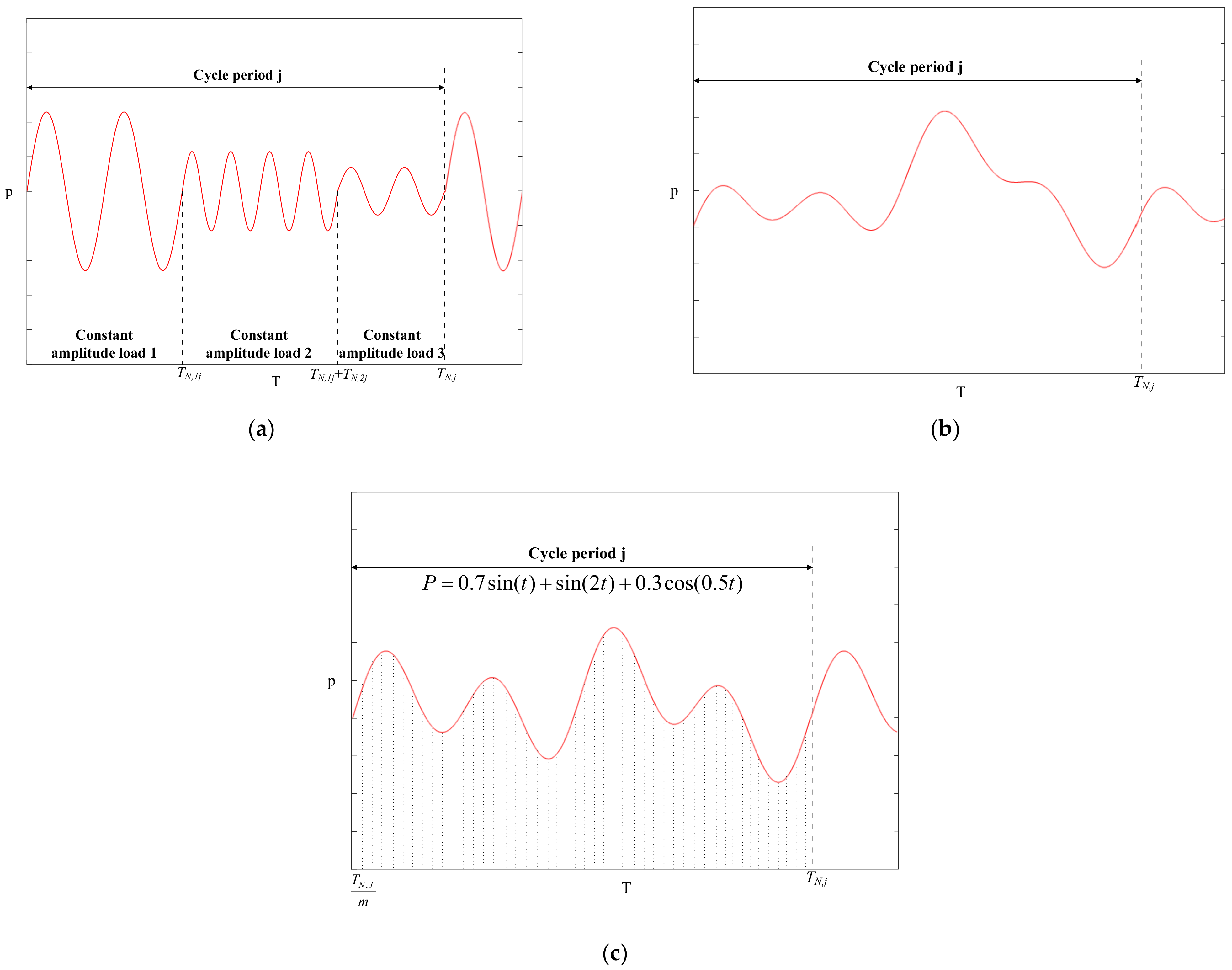
- Type 1 variable amplitude load;Suppose there are m constant amplitude loads with different amplitude sizes in the j-th cycle. The total load action time is TN,j and each constant amplitude load action time is TN,ij. The number of load cycles for the constant amplitude load is nij. The neutron dose corresponding to the i-th constant amplitude load within the j-th load cycle is:where is the initial neutron dose.The following equations can then be simply obtained by definition:
- Type 2 variable amplitude load;It is usually reasonable to select a representative load history section; assuming that it is repeated, the actual load can then be decomposed into a constant amplitude load with two parameters (range and mean value) using the rainflow-counting method. The load can be dived into m constant amplitude loads with different amplitude sizes in the j-th cycle. The neutron dose corresponding to the i-th constant amplitude load within the j-th load cycle is:The neutron doses corresponding to each constant amplitude load within the j-th load cycle are equal:
- Type 3 variable amplitude load.Suppose that the relation of load changes with time is known:Decompose TN,j into m intervals and the corresponding time of each interval is:The load amplitude corresponding to each interval is:The neutron dose corresponding to the i-th interval within the j-th load cycle is:
2.2.2. Irradiation Fatigue Reliability Model
3. Case Study and Results
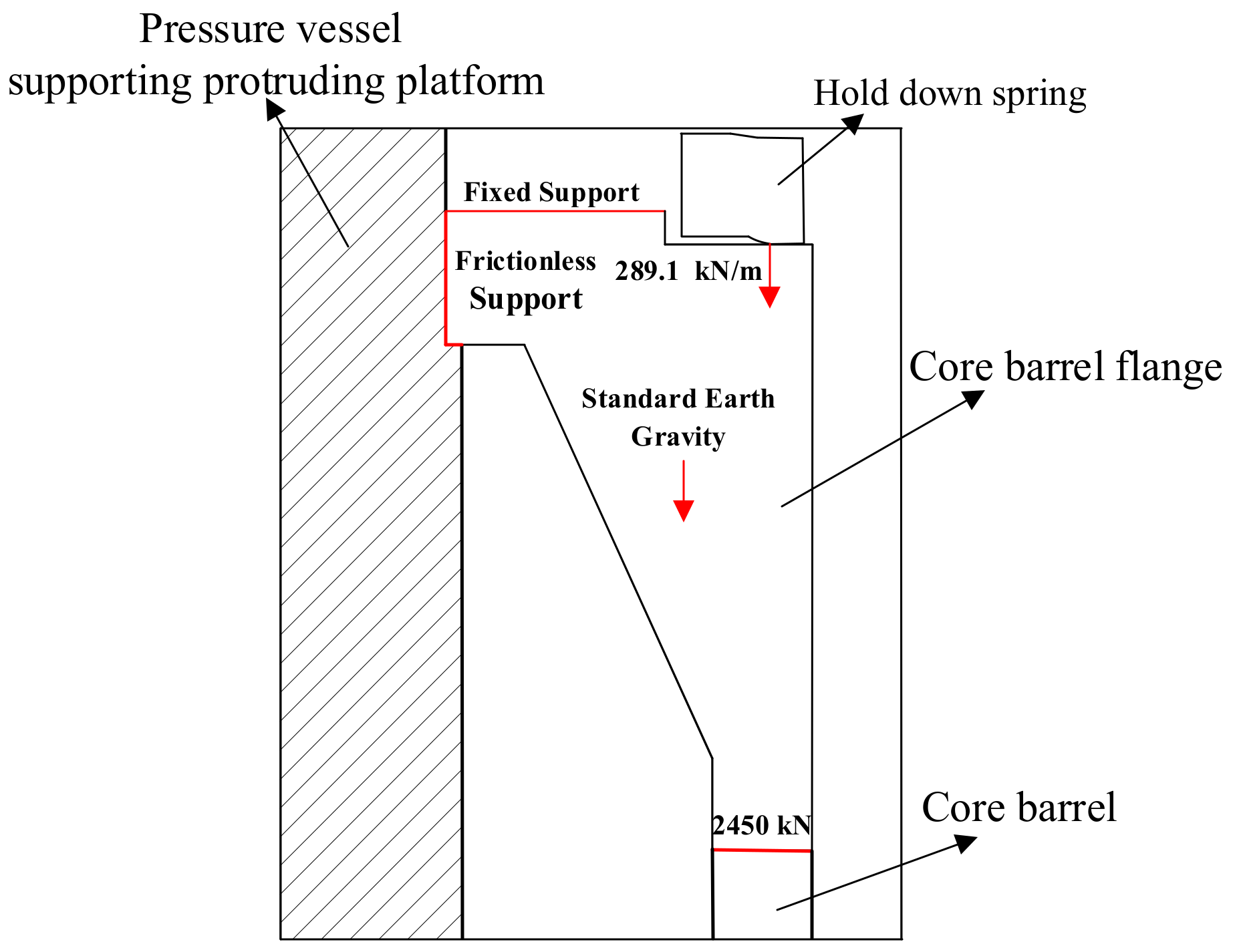
3.1. Stress–Strain Simulation of Core Barrel Flange
3.2. Fatigue Reliability Analysis without Considering Irradiation
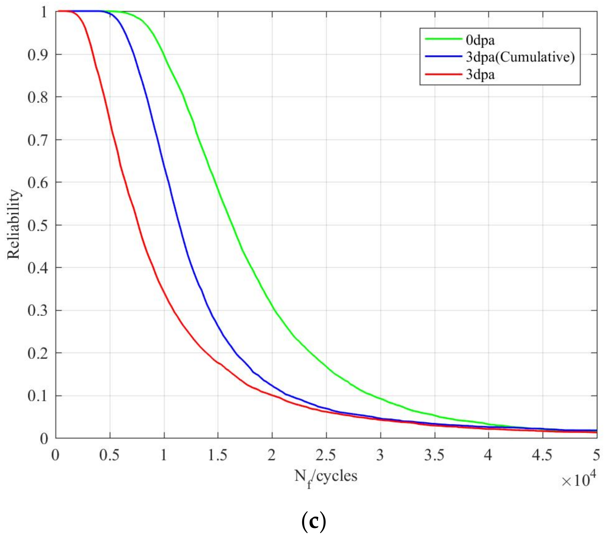
3.3. Fatigue Reliability Analysis Considering Irradiation Effect
4. Discussion
4.1. Influence of Strain Magnitude on Fatigue Reliability
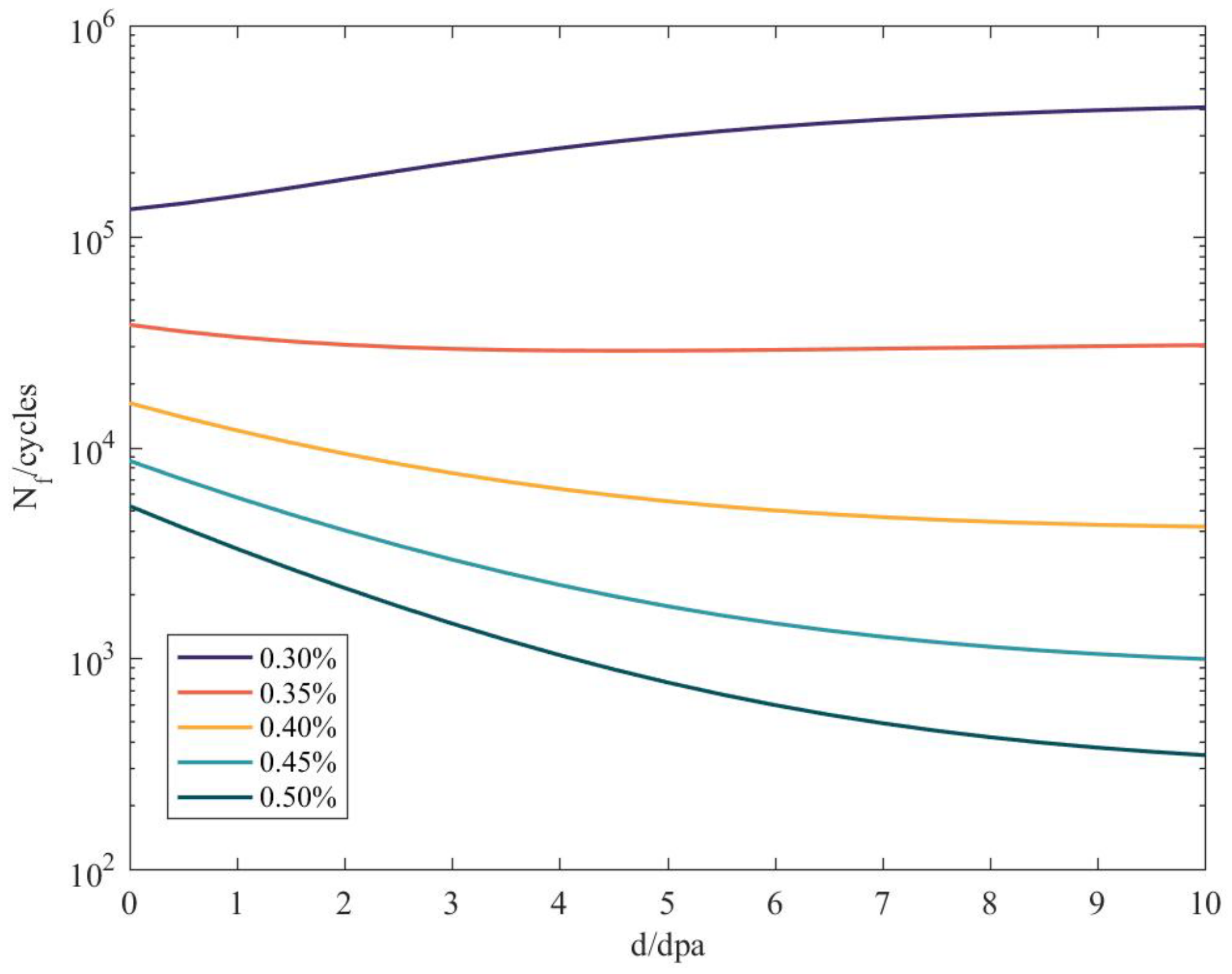
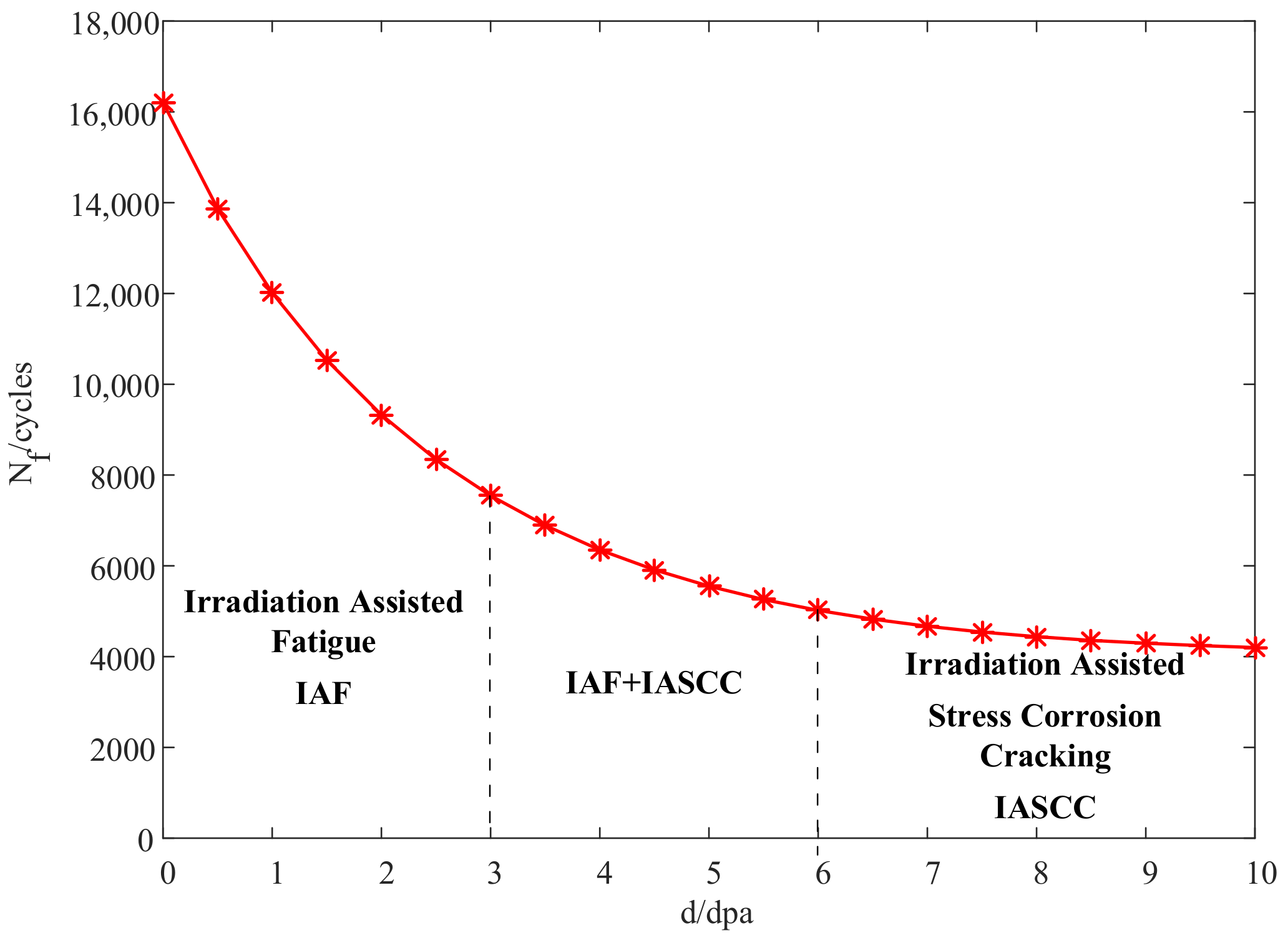
4.2. Influence of Neutron Dose on Fatigue Reliability
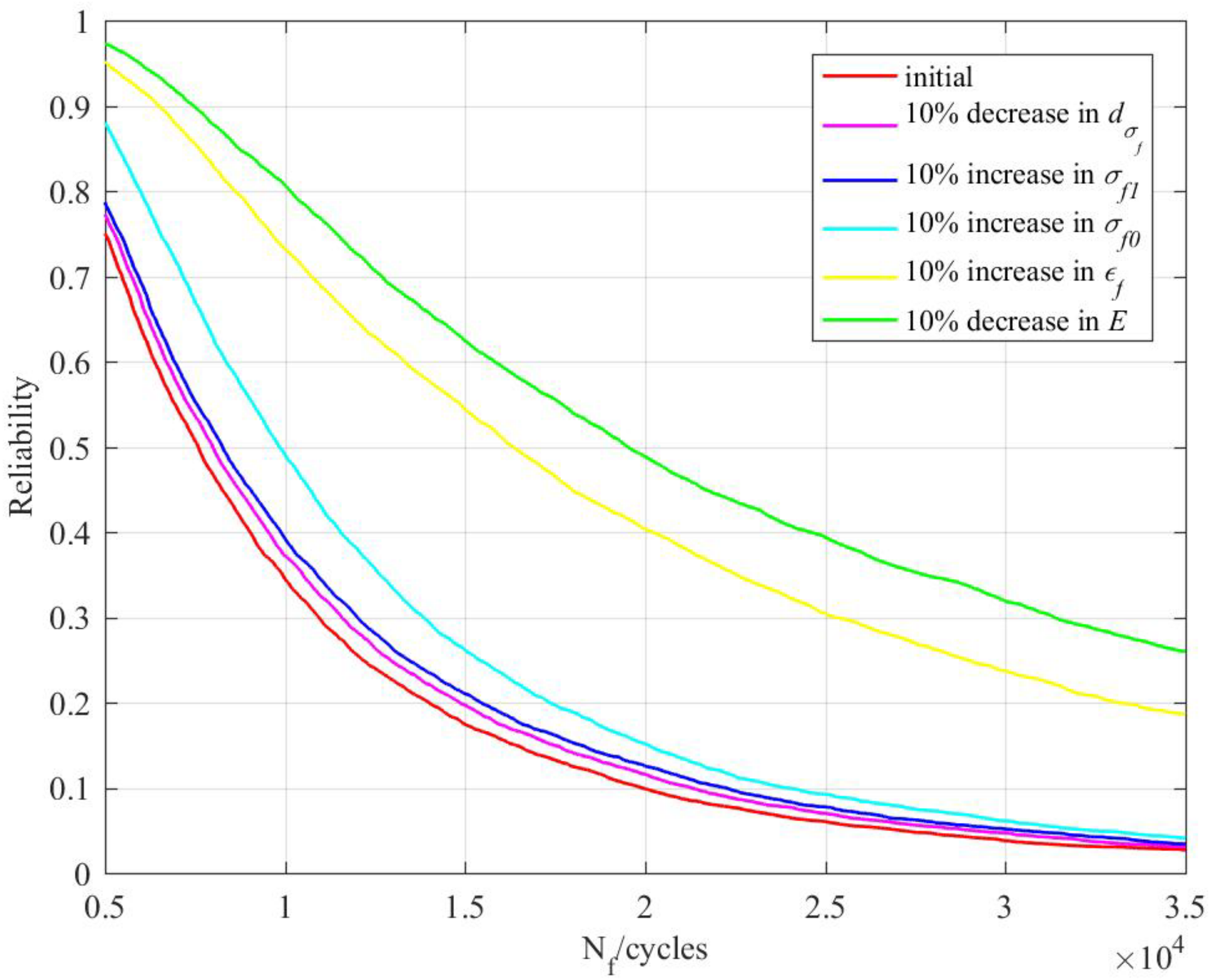
4.3. Influence of Material Performance on Fatigue Reliability
5. Conclusions
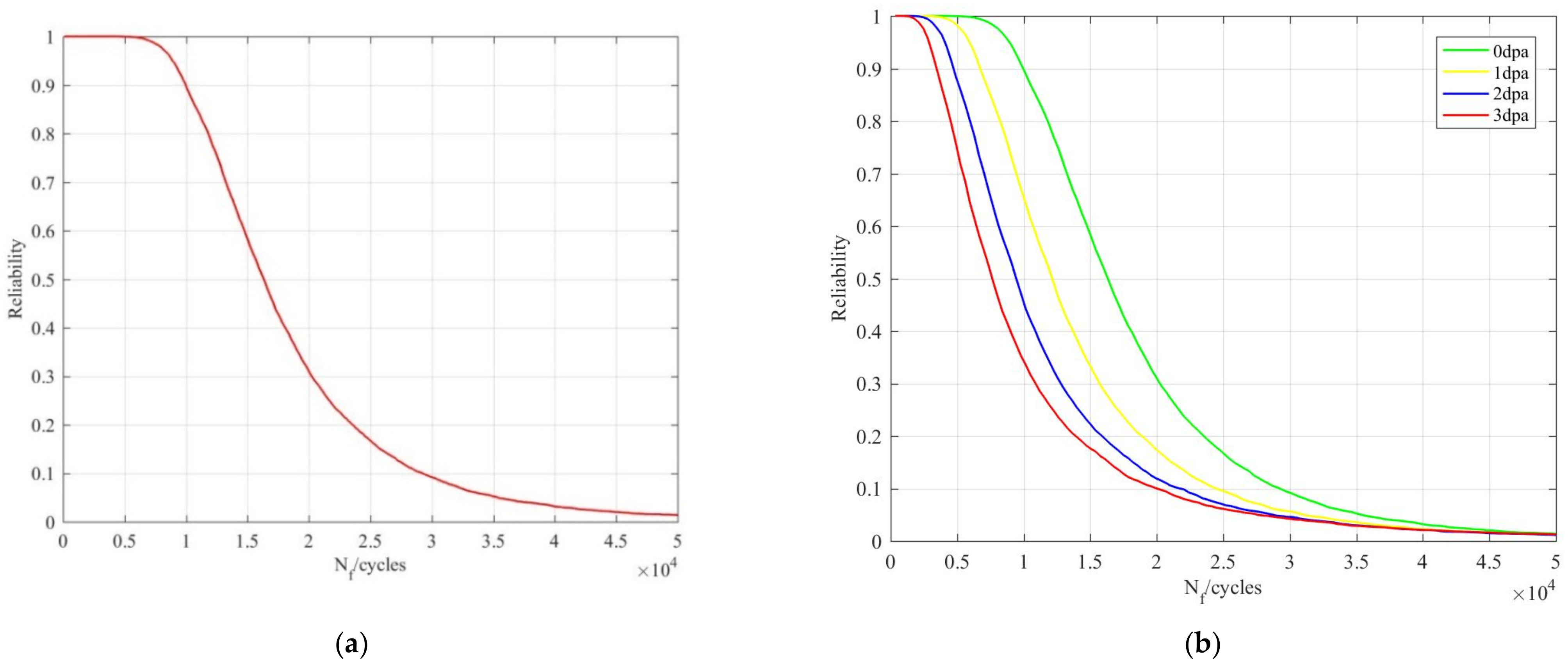
- The case study shows that the fatigue reliability model based on the cumulative effect of irradiation can be used to analyze the fatigue reliability of a reactor structure. The results showed that the fatigue life acquired by taking into account an irradiation cumulative effect was 24.3% lower than that acquired without considering an irradiation effect (the reliability was 99.78%). Considering the irradiation cumulative effect can improve the accuracy of the fatigue life prediction.
- The fatigue life increases with the accumulation of a neutron dose at a low-strain amplitude and decreases with a high-strain amplitude.
- The fatigue life changes obviously when the neutron dose is less than 5 dpa. When the neutron dose increases by a certain amount over 5 dpa, the fatigue life remains basically unchanged. Irradiation is then no longer a factor affecting the fatigue reliability. Reliability analysis should be carried out from the perspective of an irradiation-based failure mechanism (such as IASCC).
- Irradiation performance parameters only have a small influence on the reliability while the fatigue ductility coefficient and elasticity modulus have a great influence on the reliability. The reliability of the reactor structure can be greatly improved by increasing the fatigue ductility coefficient or reducing the elasticity modulus, which provides a theoretical basis for design optimization;
- In the future, tests should be carried out with different structural materials in order to determine irradiation performance parameters and fatigue performance parameters and thus improve the prediction accuracy.
Author Contributions
Funding
Data Availability Statement
Conflicts of Interest
References
- Sadekin, S.; Sirazam, Z.; Mahfuz, M.; Sarkar, R. Nuclear power as foundation of a clean energy future: A review. Energy Procedia 2019, 160, 513–518. [Google Scholar] [CrossRef]
- Lu, Y.; Khan, Z.A.; Alvarez-Alvarado, M.S.; Zhang, Y.; Huang, Z.; Imran, M. A Critical Review of Sustainable Energy Policies for the Promotion of Renewable Energy Sources. Sustainability 2020, 12, 5078. [Google Scholar] [CrossRef]
- Schneider, M.; Froggatt, A. World Nuclear Industry Status Report 2019. Available online: https://www.worldnuclearreport.org/-World-Nuclear-Industry-Status-Report-2019-.html (accessed on 20 December 2020).
- Aron, D.V.; Arutyunyan, R.V.; Bolshov, L.A.; Panchenko, S.V.; Tokarchuk, D.N. Analysis of the effect of radiation criteria for population evacuation on the socioeconomic consequences of the npp accident in fukushima prefecture (japan). At. Energy 2012, 112, 194–198. [Google Scholar] [CrossRef]
- Phalippou, C.; Ruffet, F.; Herms, E.; Balestreri, F. PWR Steam Generator Tube and AVB Wear Under Perpendicular Impacting. Asme Press. Vessel. Pip. Conf. 2013. [Google Scholar] [CrossRef]
- Tanaka, M. Investigation of V&V process for thermal fatigue issue in a sodium cooled fast reactor–Application of uncertainty quantification scheme in verification and validation with fluid-structure thermal interaction problem in T-junction piping system. Nucl. Eng. Des. 2014, 279, 91–103. [Google Scholar] [CrossRef]
- Xie, L.; Guohong, X.; Ming, Z. Evolution law of the friction coefficient and fatigue test of the hold-down spring model for nuclear reactor vessel internals. Prog. Nucl. Energy 2018, 105, 160–166. [Google Scholar] [CrossRef]
- Kiss, E. Component Reliability Considerations for New Designs and Extended Operation of Boiling Water Reactor (BWRs). Int. Conf. Nucl. Eng. 2008, 48140, 717–721. [Google Scholar] [CrossRef]
- Taheri, S. Some advances on understanding of high cycle thermal fatigue crazing. J. Press. Vessel Technol. 2006, 129, 400–410. [Google Scholar] [CrossRef]
- Shamsaei, N.; Fatemi, A.; Socie, D.F. Multiaxial fatigue evaluation using discriminating strain paths. Int. J. Fatigue 2011, 33, 597–609. [Google Scholar] [CrossRef]
- Qing, C.; Liu, J.; Gao, J.; Geng, J. Fatigue Life Analysis of Key Equipment in High Temperature Reactor Considering Nuclear Irradiation. Int. Conf. Green Mater. Environ. Eng. 2019, 453, 012052. [Google Scholar] [CrossRef]
- Manson, S.S. Fatigue behaviour in strain cycling in the low-and intermediate-cycle range. Fatigue Interdiscip. Approach 1964, 33. Available online: https://ntrs.nasa.gov/citations/19640039751 (accessed on 20 December 2020).
- Metzner, K.-J.; Wilke, U. European THERFAT project—thermal fatigue evaluation of piping system “Tee”-connections. Nucl. Eng. Des. 2005, 235, 473–484. [Google Scholar] [CrossRef]
- Sudret, B.; Guédé, Z. Probabilistic assessment of thermal fatigue in nuclear components. Nucl. Eng. Des. 2005, 235, 1819–1835. [Google Scholar] [CrossRef]
- Paffumi, E.; Nilsson, K.-F.; Taylor, N.G. Simulation of thermal fatigue damage in a 316L model pipe component. Int. J. Press. Vessel. Pip. 2008, 85, 798–813. [Google Scholar] [CrossRef]
- Brinkman, C.R.; Korth, G.E.; Beeston, J.M. Influence of irradiation on the creep/fatigue behavior of several austenitic stainless steels and Incoloy 800 at 700 C. Eff. Neutron Substruct. Mech. Prop. Met. Alloy. 1973, 473–490. [Google Scholar] [CrossRef]
- Beeston, J.M.; Brinkman, C.R. Axial fatigue of irradiated stainless steels tested at elevated temperatures. Irradiat. Eff. Struct. Alloy. Nucl. React. Appl. 1970, 419–448. [Google Scholar] [CrossRef]
- Zhong, W.; Tong, Z.; Ning, G.; Zhang, C.; Lin, H.; Yang, W. The fatigue behavior of irradiated Reactor Pressure Vessel steel. Eng. Fail. Anal. 2017, 82, 840–847. [Google Scholar] [CrossRef]
- Luzginova, N.V.; Rensman, P.; ten Pierick, P.; Hegeman, J.B.J. Low cycle fatigue of irradiated and unirradiated Eurofer97 steel at 300 °C. J. Nucl. Mater. 2011, 409, 153–155. [Google Scholar] [CrossRef]
- Chopra, O.K.; Rao, A.S. A review of irradiation effects on LWR core internal materials–IASCC susceptibility and crack growth rates of austenitic stainless steels. J. Nucl. Mater. 2011, 409, 235–256. [Google Scholar] [CrossRef]
- Fuller, R.W.; Shamsaei, N. Fatigue Life Predictions for Irradiated Stainless Steels. In TMS 2015 144th Annual Meeting Exhibition; Springer: Cham, Switzerland, 2015. [Google Scholar] [CrossRef]
- Sun, B.; Yu, L.; Zili, W.; Zhifeng, L.; Quan, X.; Yi, R.; Qiang, F.; Dezhen, Y.; Cheng, Q. Physics-of-failure and computer-aided simulation fusion approach with a software system for electronics reliability analysis. Eksploat. I Niezawodn. Maint. Reliab. 2020, 22, 340. [Google Scholar] [CrossRef]
- Cui, W. A state-of-the-art review on fatigue life prediction methods for metal structures. J. Mar. Sci. Technol. 2002, 7, 43–56. [Google Scholar] [CrossRef]
- Li, S.; Xie, X.; Cheng, C.; Tian, Q. A modified Coffin-Manson model for ultra-low cycle fatigue fracture of structural steels considering the effect of stress triaxiality. Eng. Fract. Mech. 2020, 237, 107223. [Google Scholar] [CrossRef]
- Schneider, H.-C.; Dafferner, B.; Aktaa, J. Embrittlement behaviour of different international low activation alloys after neutron irradiation. J. Nucl. Mater. 2001, 295, 16–20. [Google Scholar] [CrossRef]
- Nogami, S.; Guan, W.; Toyota, M.; Hasegawa, A. Fatigue life prediction of ferritic/martensitic steels based on universal slope equations and tensile properties obtained using small specimen. Fusion Eng. Des. 2017, 125, 330–336. [Google Scholar] [CrossRef]
- Chudzik, A.; Warda, B. Fatigue life prediction of a radial cylindrical roller bearing subjected to a combined load using FEM. Eksploat. I Niezawodn. Maint. Reliab. 2020, 22, 212–220. [Google Scholar] [CrossRef]
- Vareda, L.V.; Spinelli, D. Fatigue, monotonic and fracture toughness properties of a Cr–Mn–N steel. Int. J. Fatigue 2001, 23, 857–863. [Google Scholar] [CrossRef]

| Parameter Name | Distribution Type | Mean Value | Standard Deviation |
|---|---|---|---|
| Yield strength | Normal distribution | 109 Mpa | 5.45 Mpa |
| Density | Truncated normal distribution | 7930 | 396.5 |
| Poisson’s ratio | Truncated normal distribution | 0.3 | 0.015 |
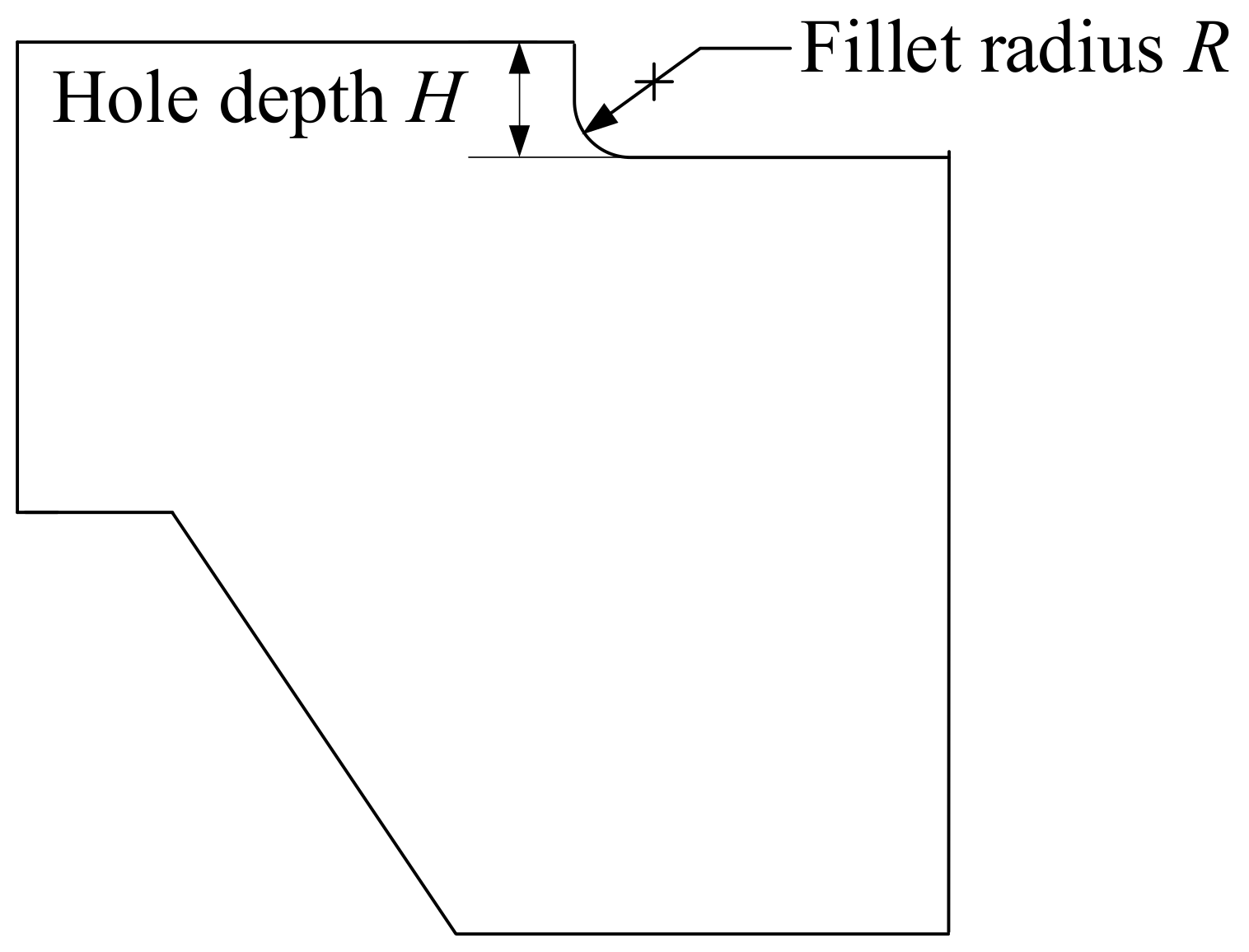
| Fillet radius | Normal distribution | 3.8 mm | 0.019 mm |
| Hole depth | Normal distribution | 14.6 mm | 0.072 mm |
| Material | b | c | E | ||
|---|---|---|---|---|---|
| 304LN stainless steel | −0.055 | −0.529 | 1032 MPa | 0.2422 | 194 GPa |
Publisher’s Note: MDPI stays neutral with regard to jurisdictional claims in published maps and institutional affiliations. |
© 2021 by the authors. Licensee MDPI, Basel, Switzerland. This article is an open access article distributed under the terms and conditions of the Creative Commons Attribution (CC BY) license (http://creativecommons.org/licenses/by/4.0/).
Share and Cite
Sun, B.; Pan, J.; Wang, Z.; Ren, Y.; Mazurkiewicz, D.; Jasiulewicz-Kaczmarek, M.; Antosz, K. Fatigue Reliability Analysis Method of Reactor Structure Considering Cumulative Effect of Irradiation. Materials 2021, 14, 801. https://doi.org/10.3390/ma14040801
Sun B, Pan J, Wang Z, Ren Y, Mazurkiewicz D, Jasiulewicz-Kaczmarek M, Antosz K. Fatigue Reliability Analysis Method of Reactor Structure Considering Cumulative Effect of Irradiation. Materials. 2021; 14(4):801. https://doi.org/10.3390/ma14040801
Chicago/Turabian StyleSun, Bo, Junlin Pan, Zili Wang, Yi Ren, Dariusz Mazurkiewicz, Małgorzata Jasiulewicz-Kaczmarek, and Katarzyna Antosz. 2021. "Fatigue Reliability Analysis Method of Reactor Structure Considering Cumulative Effect of Irradiation" Materials 14, no. 4: 801. https://doi.org/10.3390/ma14040801
APA StyleSun, B., Pan, J., Wang, Z., Ren, Y., Mazurkiewicz, D., Jasiulewicz-Kaczmarek, M., & Antosz, K. (2021). Fatigue Reliability Analysis Method of Reactor Structure Considering Cumulative Effect of Irradiation. Materials, 14(4), 801. https://doi.org/10.3390/ma14040801