
Study on Creep Damage of Ni-Based Superalloy Caused by Variable Load Conditions at Elevated Temperatures

Abstract
:1. Introduction
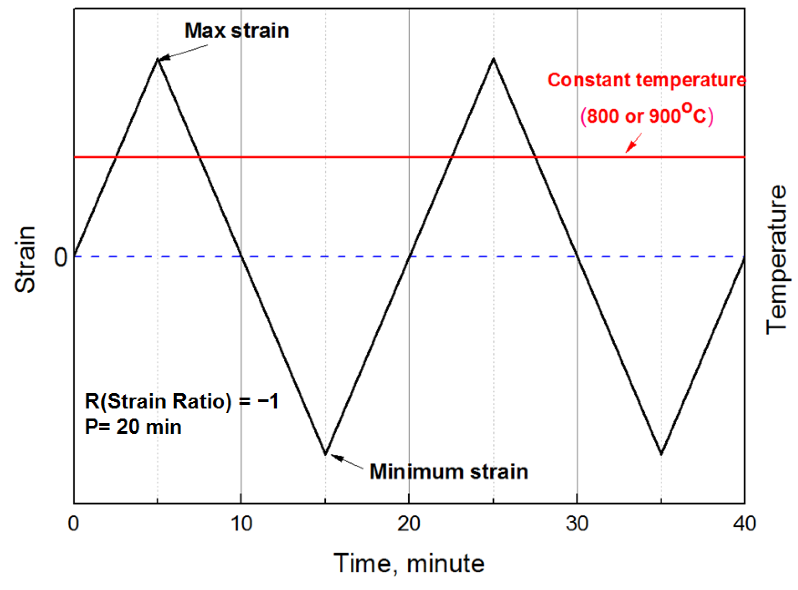
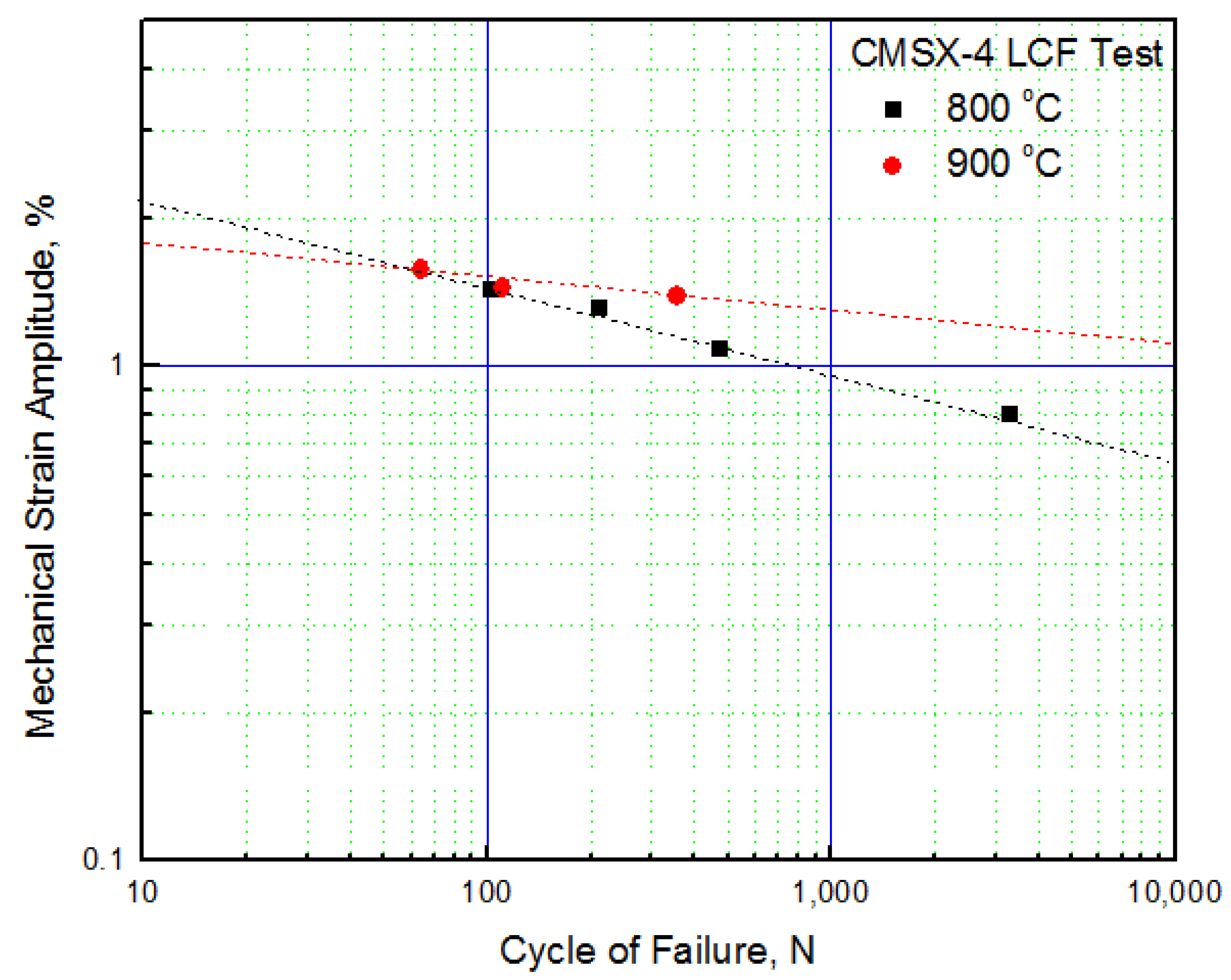
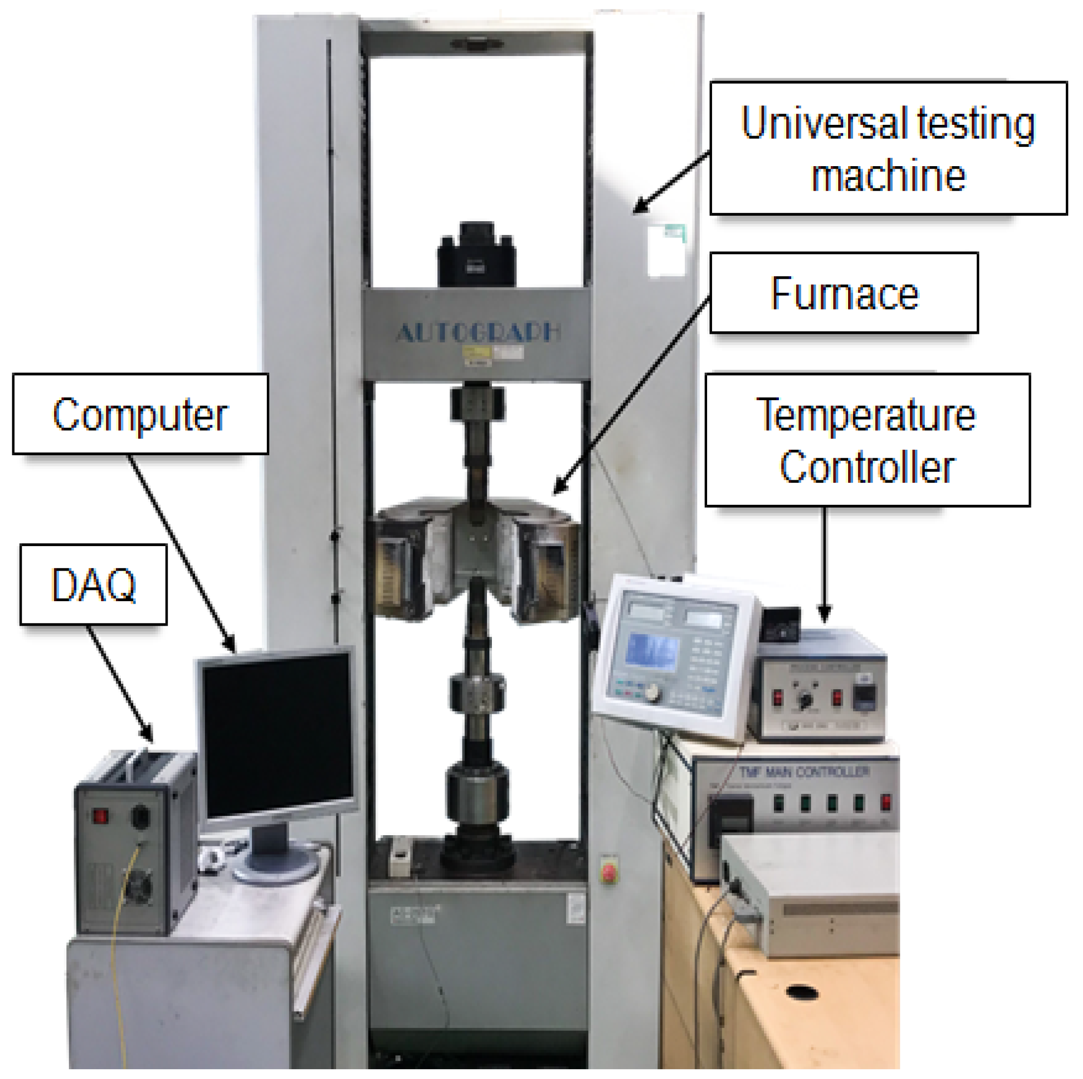
2. Low-Cycle Fatigue Test
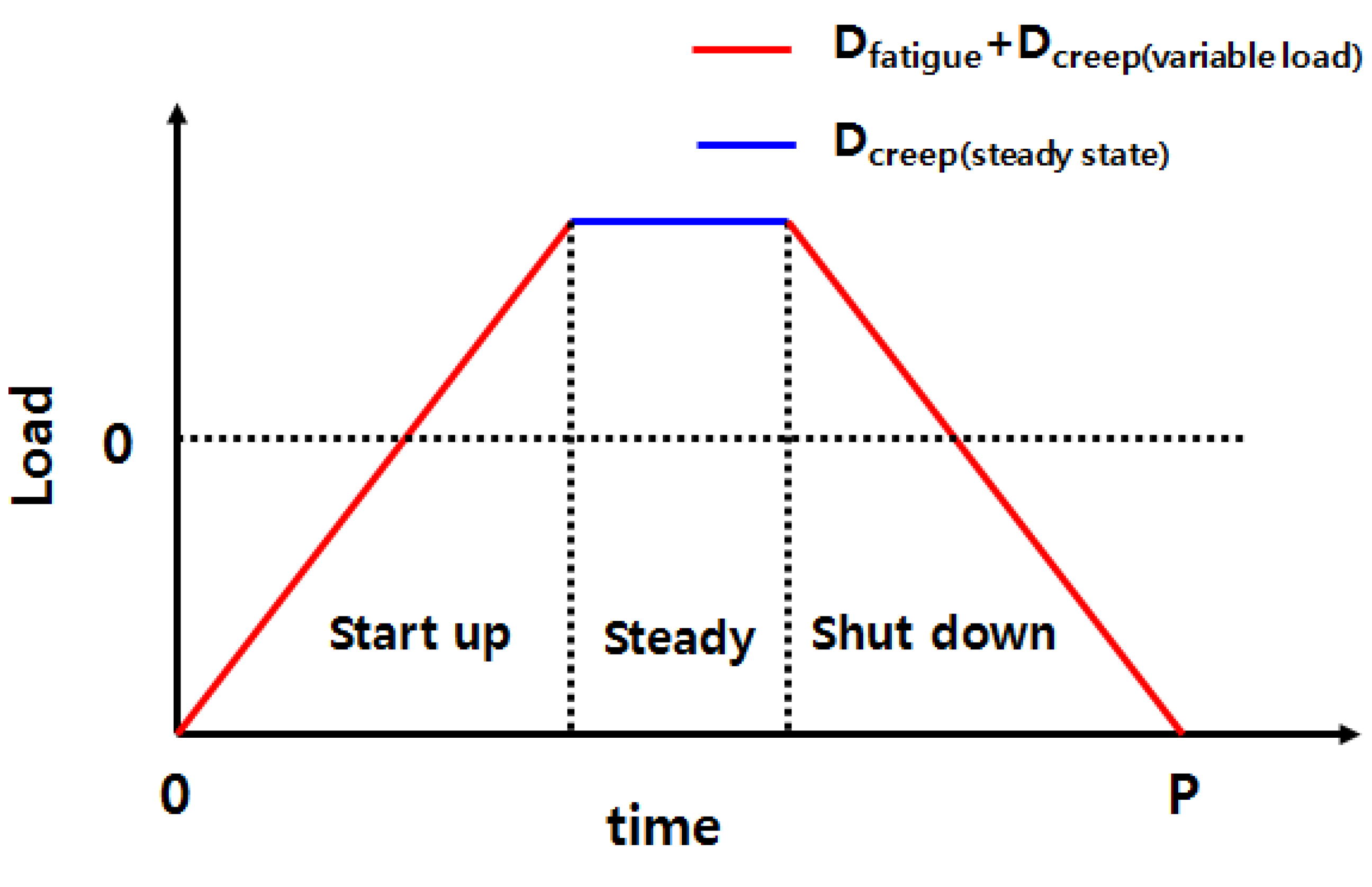
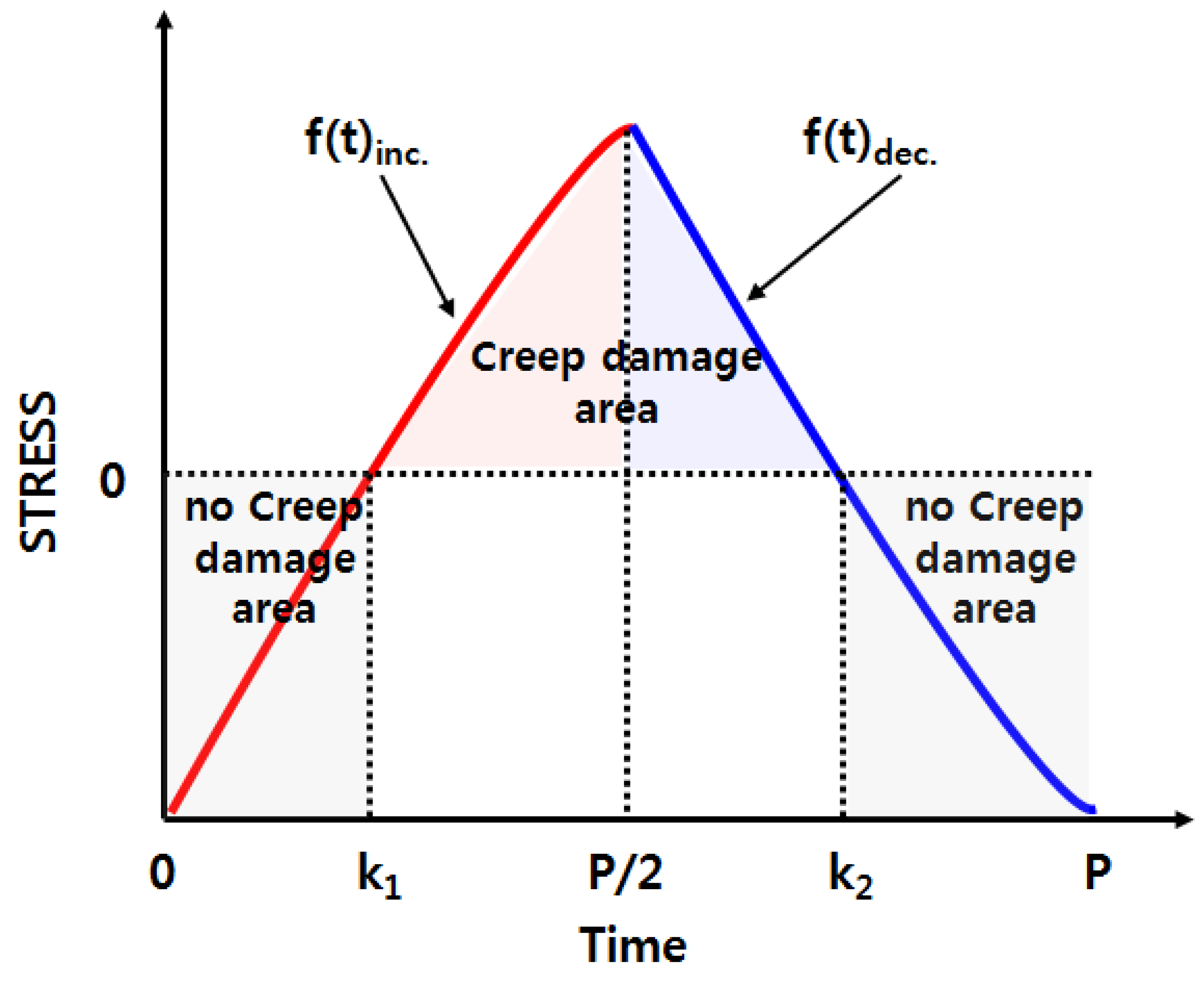
3. Derivation of Creep Damage Caused by Variable Load
4. Derivation of Creep Damage That Occurs during Low-Cycle Fatigue
5. Discussion
6. Conclusions
- By integrating the reciprocal of the creep rupture time with respect to time, the amount of creep damage occurring per unit time and the amount of creep damage occurring per cycle were derived;
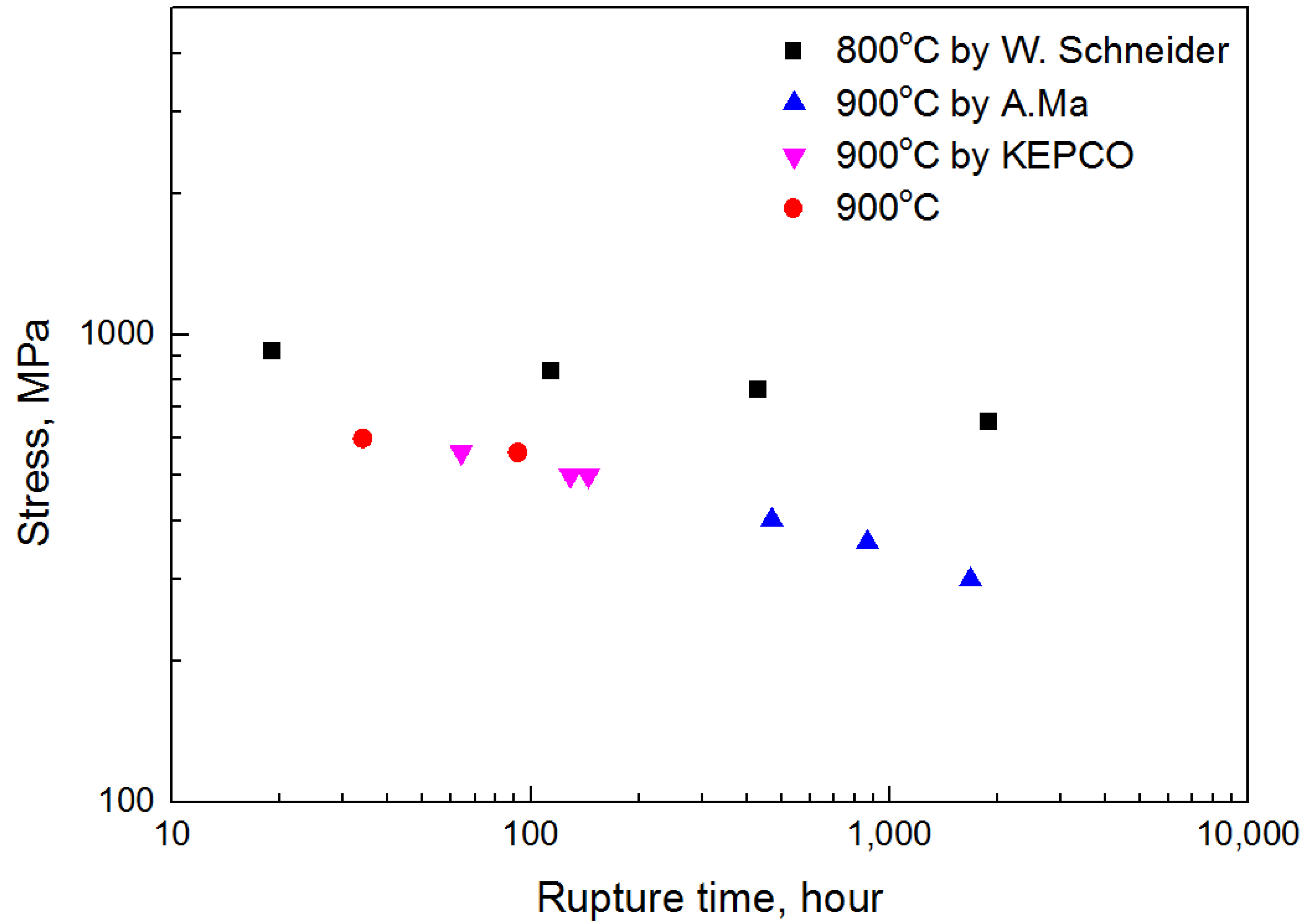
- The relationship between rupture time and stress was derived from the creep test result and expressed as a time integral expression for stress;
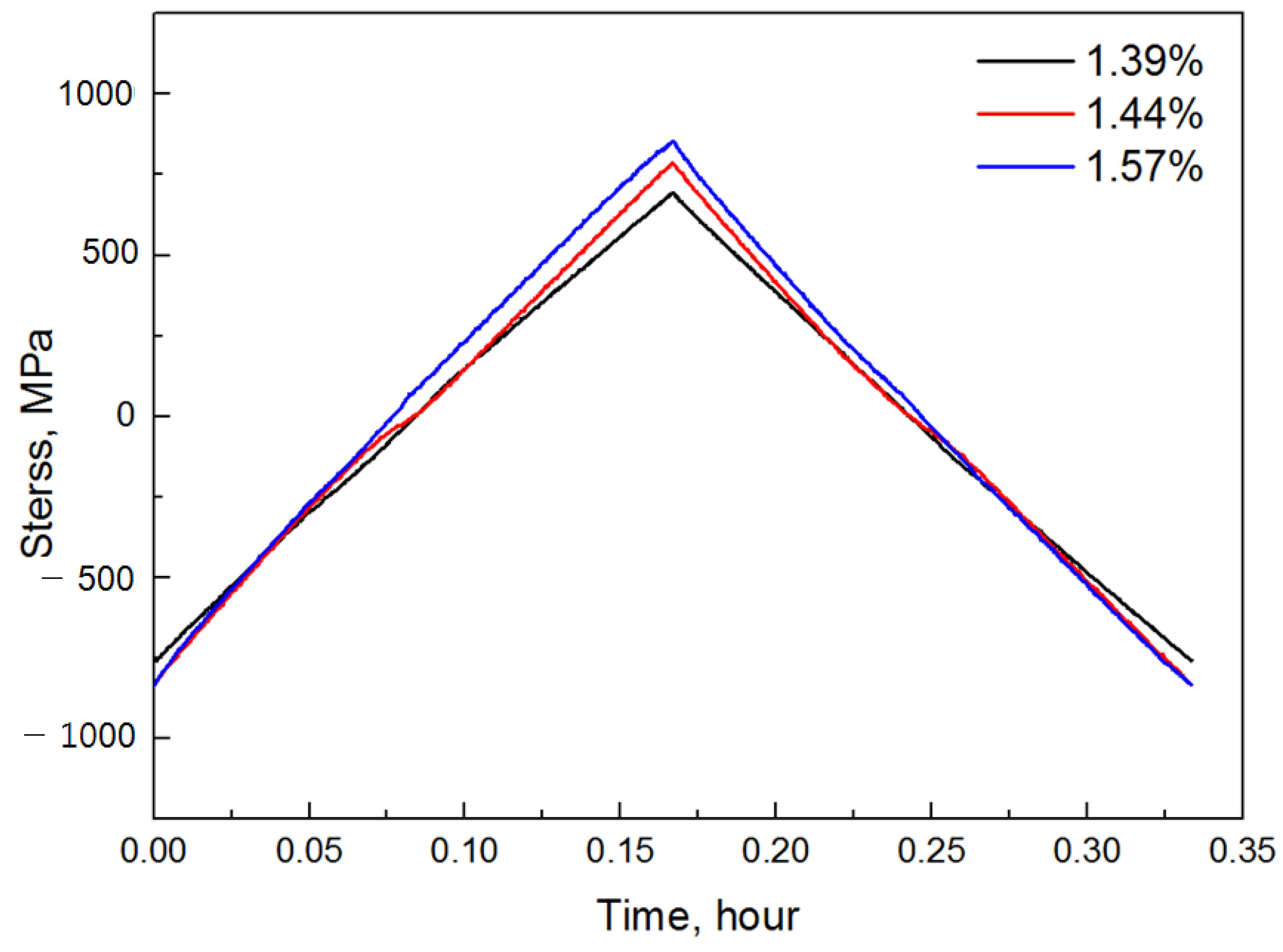
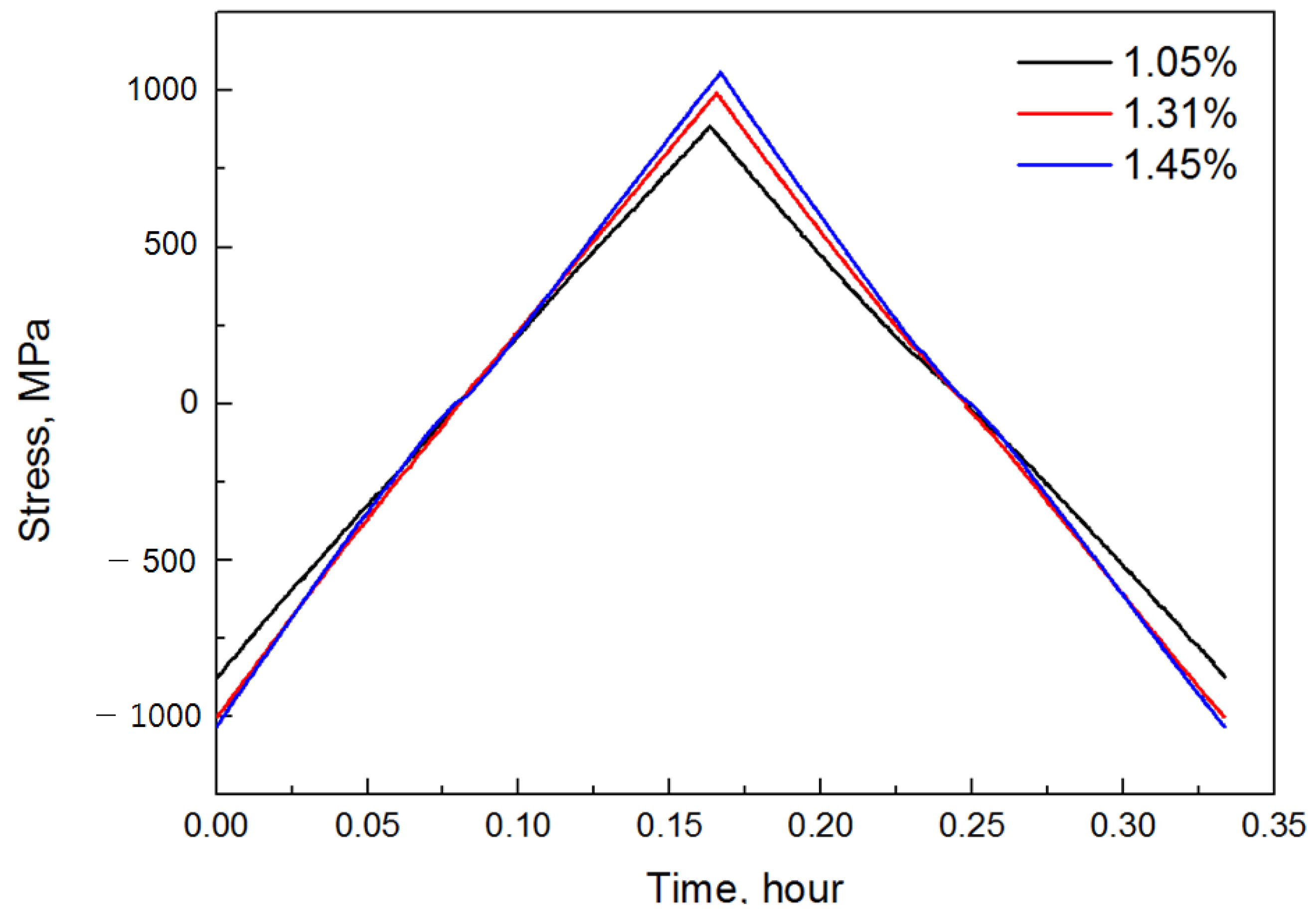
- The stress change with time was derived from the fatigue test result, and the stress was expressed as a function of time;
- The section where creep actually acted was classified according to the result of stress change over time in the fatigue test.
Author Contributions
Funding
Acknowledgments
Conflicts of Interest
References
- Geetika, K.S.; Rayapati, S.; Subrata, M. Comparison and selection of suitable materials applicable for gas turbine blades. Mater. Today Proc. 2021, 46, 8864–8870. [Google Scholar]
- Swain, B.K.; Mallick, P.; Patel, S.; Roshan, R.; Mohapatra, S.; Bhuyan, S.; Priyadarshini, M.; Behera, B.; Samal, S.; Behera, A. Failure analysis and materials development of gas turbine blades. Mater. Today Proc. 2020, 33, 5143–5146. [Google Scholar] [CrossRef]
- Mohd, S.; Parth, M.; Ashhad, I. Analysis and structural design of various turbine blades under variable conditions: A review. Adv. Mater. Res. 2019, 8, 11–24. [Google Scholar]
- Yao, Z.; Zhou, B.; Yao, K.; Wang, H.; Dong, J.; Davey, T. Influence and Sensitivity of Temperature and Microstructure on the Fluctuation of Creep Properties in Ni-Base Superalloy. Materials 2020, 13, 4758. [Google Scholar] [CrossRef]
- Zhang, S.; Xu, Y.; Fu, H.; Wen, Y.; Wang, Y.; Liu, X. Low-Cycle Fatigue Crack Initiation Simulation and Life Prediction of Powder Superalloy Considering Inclusion-Matrix Interface Debonding. Materials 2021, 14, 4018. [Google Scholar] [CrossRef] [PubMed]
- Rajabinezhad, M.; Bahrami, A.; Mousavinia, M.; Seyedi, S.J.; Taheri, P. Corrosion-Fatigue Failure of Gas-Turbine Blades in an Oil and Gas Production Plant. Materials 2020, 13, 900. [Google Scholar] [CrossRef] [PubMed] [Green Version]
- Kolagar, A.M.; Tabrizi, N.; Cheraghzadeh, M.; Shahriari, M.S. Failure analysis of gas turbine first stage blade made of nickelbased superalloy. Case Stud. Eng. Fail. Anal. 2017, 8, 61–68. [Google Scholar] [CrossRef]
- Poursaeidi, E.; Aieneravaie, M.; Mohammadi, M.R. Failure analysis of a second stage blade in a gas turbine engine. Eng. Fail. Anal. 2008, 15, 1111–1129. [Google Scholar] [CrossRef]
- Kwon, H.-J.; Lee, D.; Lee, Y.-K. Failure analysis of blades and vanes of a compressor for a gas turbine engine. Eng. Fail. Anal. 2021, 124, 105386. [Google Scholar] [CrossRef]
- Rayapati, S. Gas turbine blade failure scenario due to thermal loads in case of Nickel based super alloys. Mater. Today Proc. 2021, 46, 8119–8126. [Google Scholar] [CrossRef]
- Angerer, M.; Kahlert, S.; Spliethoff, H. Transient simulation and fatigue evaluation of fast gas turbine startups and shutdowns in a combined cycle plant with an innovative thermal buffer storage. Energy 2017, 130, 246–257. [Google Scholar] [CrossRef]
- Ding, B.; Ren, W.; Peng, J.; Zheng, T.; Hou, L.; Yu, J.; Ren, Z.; Zhong, Y. Damage mechanism and life prediction based on tensile-stress- and compressive-stress-dominated low-cycle fatigue of a directionally solidified Ni-based superalloy DZ445. Mater. Sci. Eng. A 2019, 742, 478–492. [Google Scholar] [CrossRef]
- Holländer, D.; Kulawinski, D.; Weidner, A.; Thiele, M.; Biermann, H.; Gampe, U. Small-scale specimen testing for fatigue life assessment of service-exposed industrial gas turbine blades. Int. J. Fatigue 2016, 92, 262–271. [Google Scholar] [CrossRef]
- Marahleh, G.; Kheder, A.; Hamad, H. Creep life prediction of service-exposed turbine blades. Mater. Sci. Eng. A 2006, 433, 305–309. [Google Scholar] [CrossRef]
- Gu, S.; Gao, H.; Wen, Z.; Pei, H.; Li, Z.; Zhao, Y.; Yue, Z. Creep characteristics of directionally solidified turbine blades based on the difference in original casting characteristics. J. Alloys Compd. 2021, 884, 161055. [Google Scholar] [CrossRef]
- Zhang, C.; Wang, P.; Wen, Z.; Xu, Z.; He, P.; Yue, Z. Study on creep properties of nickel-based superalloy blades based on microstructure characteristics. J. Alloys Compd. 2021, 890, 161710. [Google Scholar] [CrossRef]
- Chen, J.; Huo, Q.; Chen, J.; Wu, Y.; Li, Q.; Xiao, C.; Hui, X. Tailoring the creep properties of second-generation Ni-based single crystal superalloys by composition optimization of Mo, W and Ti. Mater. Sci. Eng. A 2020, 799, 140163. [Google Scholar] [CrossRef]
- Chen, S.; Wei, D.; Jiang, X. A new fatigue life prediction model considering the creep-fatigue interaction effect based on the Walker total strain equation. Chin. J. Aeronaut. 2020, 33, 2382–2394. [Google Scholar] [CrossRef]
- Ding, B.; Ren, W.; Peng, J.; Zhong, Y.; Yu, J. Influence of dwell time on the creep–fatigue behavior of a directionally solidified Ni-based superalloy DZ445 at 850 °C. Mater. Sci. Eng. A 2018, 725, 319–328. [Google Scholar] [CrossRef]
- Kashinga, R.J.; Zhao, L.G.; Silberschmidt, V.V.; Farukh, F.; Barnard, N.C.; Whittaker, M.T.; Proprentner, D.; Shollock, B.; McColvin, G. Low cycle fatigue of a directionally solidified nickel-based superalloy: Testing, characterisation and modelling. Mater. Sci. Eng. A 2017, 708, 503–513. [Google Scholar] [CrossRef]
- Lee, J.-M.; Wee, S.; Yun, J.; Song, H.; Kim, Y.; Koo, J.-M.; Seok, C.-S. Life Prediction of IN738LC Considering Creep Damage under Low Cycle Fatigue. Int. J. Precis. Eng. Manuf. GT 2018, 5, 311–316. [Google Scholar] [CrossRef]
- Andrés, D.; Lacalle, R.; Álvarez, J.A. Creep property evaluation of light alloys by means of the Small Punch test: Creep master curves. Mater. Des. 2016, 96, 122–130. [Google Scholar] [CrossRef]
- Zhou, H.; Mehmanparast, A.; Nikbin, K. Determination of Long-Term Creep Properties for 316H Steel Using Short-Term Tests on Pre-strained Material. Exp. Tech. 2021, 45, 549–560. [Google Scholar] [CrossRef]
- Zhang, Y.; Jing, H.-Y.; Xu, L.-Y.; Han, Y.-D.; Zhao, L.; Xie, X.-S.; Zhu, Q.-H. Creep Behavior and Life Assessment of a Novel Heat-Resistant Austenite Steel and Its Weldment. Acta Met. Sin. (Engl. Lett.) 2018, 32, 638–650. [Google Scholar] [CrossRef] [Green Version]
- Ma, A.; Dye, D.; Reed, R.C. A model for the creep deformation behaviour of single-crystal superalloy CMSX-4. Acta Mater. 2008, 56, 1657–1670. [Google Scholar] [CrossRef]
- Schneider, W.; Hamme, J.; Mughrabi, H. Creep Deformation and Rupture Behavior of the Monocrystalline Syperalloy CMSX-4—A Comparison with the Alloy SRR 99; The Minerals, Metals and Materials Society: Warrendale, PA, USA, 1992; pp. 589–598. [Google Scholar]
- Gas Turbine Material Property Evaluation and Data Base Development. Korea Electric Power Corporation (KEPCO). Technical Report, Report of Knowledge Economy Technology Innovation Project. Available online: https://scienceon.kisti.re.kr/commons/util/originalView.do?cn=TRKO201300025057&dbt=TRKO&rn= (accessed on 15 September 2021).
- Hu, D.; Wang, R. Experimental study on creep–fatigue interaction behavior of GH4133B superalloy. Mater. Sci. Eng. A 2009, 515, 183–189. [Google Scholar] [CrossRef]
- Mao, J.; Li, X.; Wang, D.; Zhong, F.; Luo, L.; Bao, S.; Ding, Z. Experimental study on creep-fatigue behaviors of chinese P92 steel with consideration of several important factors. Int. J. Fatigue 2020, 142, 105900. [Google Scholar] [CrossRef]
- Ma, L.; Wang, Y.; Wang, M.; Xue, B.; Duan, L. Mechanical properties of rock salt under combined creep and fatigue. Int. J. Rock Mech. Min. Sci. 2021, 141, 104654. [Google Scholar] [CrossRef]
- Matan, N.; Cox, D.; Carter, P.; Rist, M.; Rae, C.; Reed, R. Creep of CMSX-4 superalloy single crystals: Effects of misorientation and temperature. Acta Mater. 1999, 47, 1549–1563. [Google Scholar] [CrossRef]
- Reed, R.C.; Matan, N.; Cox, D.C.; Rist, M.A.; Rae, C.M.F. Creep of CMSX-4 superalloy single crystals: Effects of rafting at high temperature. Acta Mater. 1999, 47, 3367–3381. [Google Scholar] [CrossRef]


| Cr | Co | Mo | Re | W |
|---|---|---|---|---|
| 6.5 | 9 | 0.6 | 3.0 | 6 |
| Al | Ti | Ta | Hf | Ni |
| 5.6 | 1.0 | 6.5 | 0.1 | Rest |
| Strain | |||
|---|---|---|---|
| 800 °C | 1.05% | 1.31% | 1.45% |
| 900 °C | 1.39% | 1.44% | 1.57% |
| A (MPa−n·hour) | n | |
|---|---|---|
| 800 °C (R2 = 0.955) | 1174 | −0.074 |
| 900 °C (R2 = 0.973) | 1200 | −0.18 |
| Linear | 2nd Poly | Exponential | |
|---|---|---|---|
| 800 °C | 0.999513 | 0.99971 | 0.99977 |
| 900 °C | 0.998953 | 0.99951 | 0.999593 |
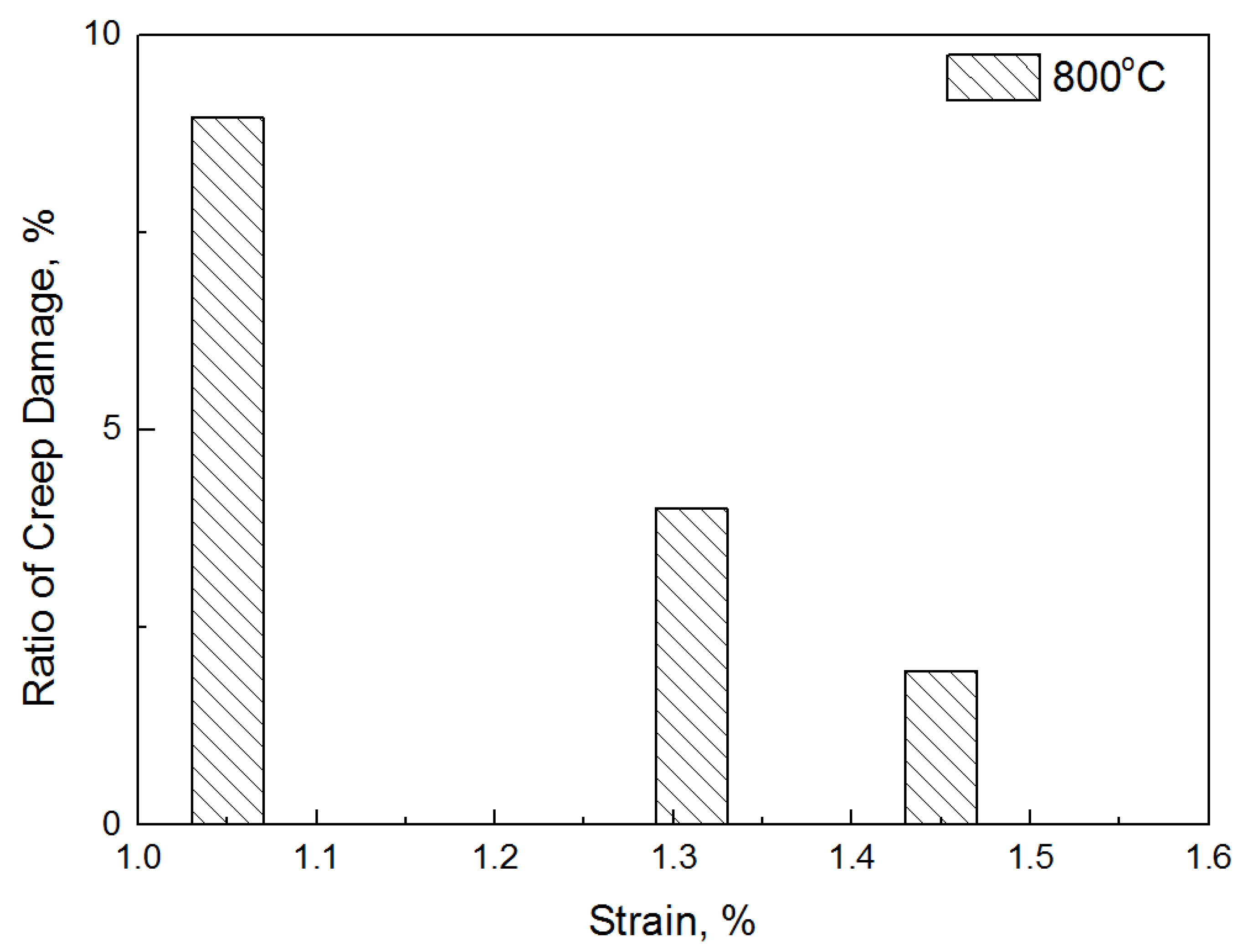
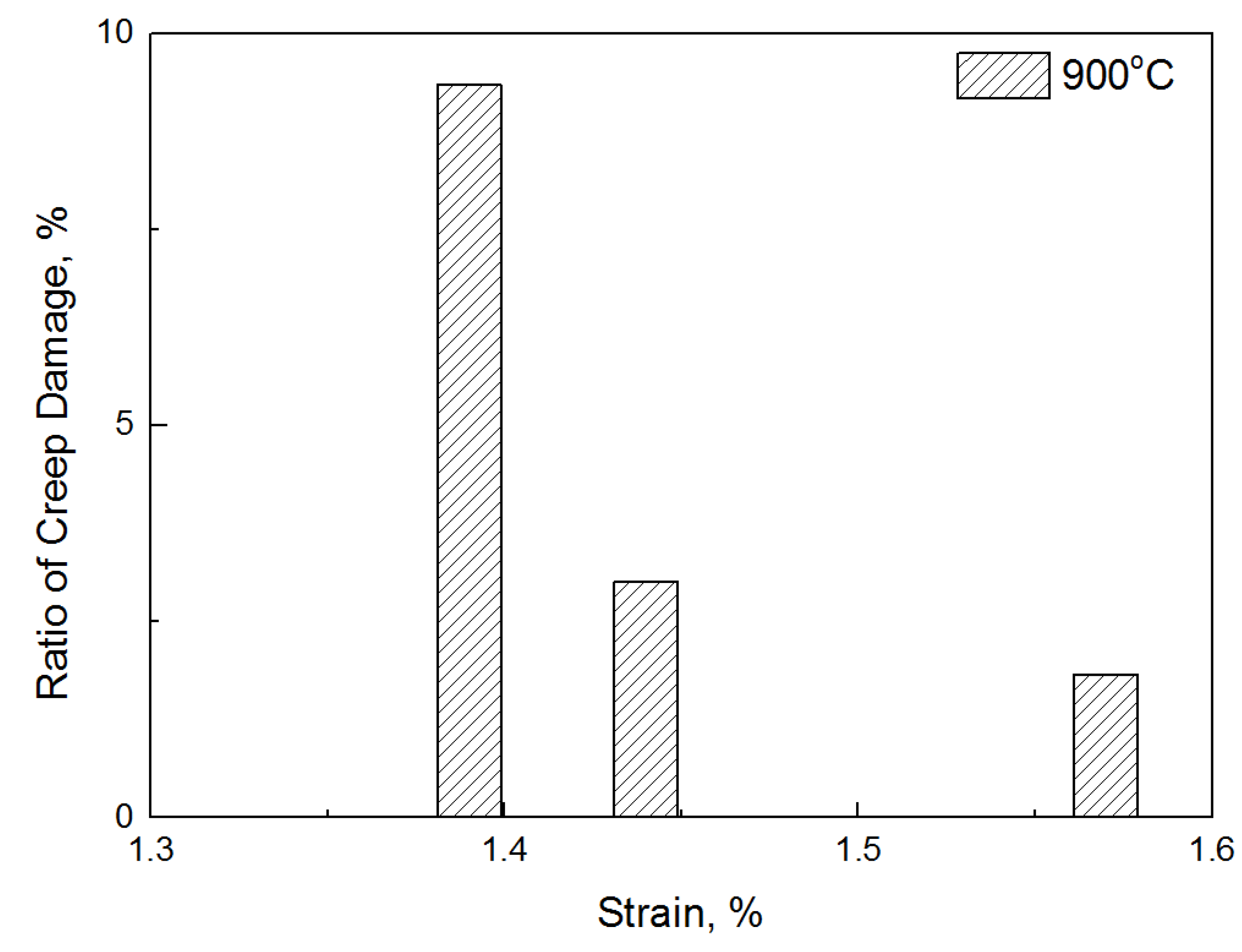
| Temperature | Strain | Dcreep |
|---|---|---|
| 800 °C | 1.05% | 1.885 × 10⁻⁴ |
| 1.31% | 1.893 × 10⁻⁴ | |
| 1.45% | 1.896 × 10⁻⁴ | |
| 900 °C | 1.39% | 2.616 × 10⁻⁴ |
| 1.44% | 2.711 × 10⁻⁴ | |
| 1.57% | 2.853 × 10⁻⁴ |
Publisher’s Note: MDPI stays neutral with regard to jurisdictional claims in published maps and institutional affiliations. |
© 2021 by the authors. Licensee MDPI, Basel, Switzerland. This article is an open access article distributed under the terms and conditions of the Creative Commons Attribution (CC BY) license (https://creativecommons.org/licenses/by/4.0/).
Share and Cite
Wee, S.; Kim, K.; Park, K.; Seok, C. Study on Creep Damage of Ni-Based Superalloy Caused by Variable Load Conditions at Elevated Temperatures. Materials 2021, 14, 6971. https://doi.org/10.3390/ma14226971
Wee S, Kim K, Park K, Seok C. Study on Creep Damage of Ni-Based Superalloy Caused by Variable Load Conditions at Elevated Temperatures. Materials. 2021; 14(22):6971. https://doi.org/10.3390/ma14226971
Chicago/Turabian StyleWee, Sunguk, Keekeun Kim, Kibum Park, and Changsung Seok. 2021. "Study on Creep Damage of Ni-Based Superalloy Caused by Variable Load Conditions at Elevated Temperatures" Materials 14, no. 22: 6971. https://doi.org/10.3390/ma14226971
APA StyleWee, S., Kim, K., Park, K., & Seok, C. (2021). Study on Creep Damage of Ni-Based Superalloy Caused by Variable Load Conditions at Elevated Temperatures. Materials, 14(22), 6971. https://doi.org/10.3390/ma14226971