
Friction Stir Welding of Thick Plates of 4Y3Gd Mg Alloy: An Investigation of Microstructure and Mechanical Properties


 , and
, and
Abstract
:1. Introduction
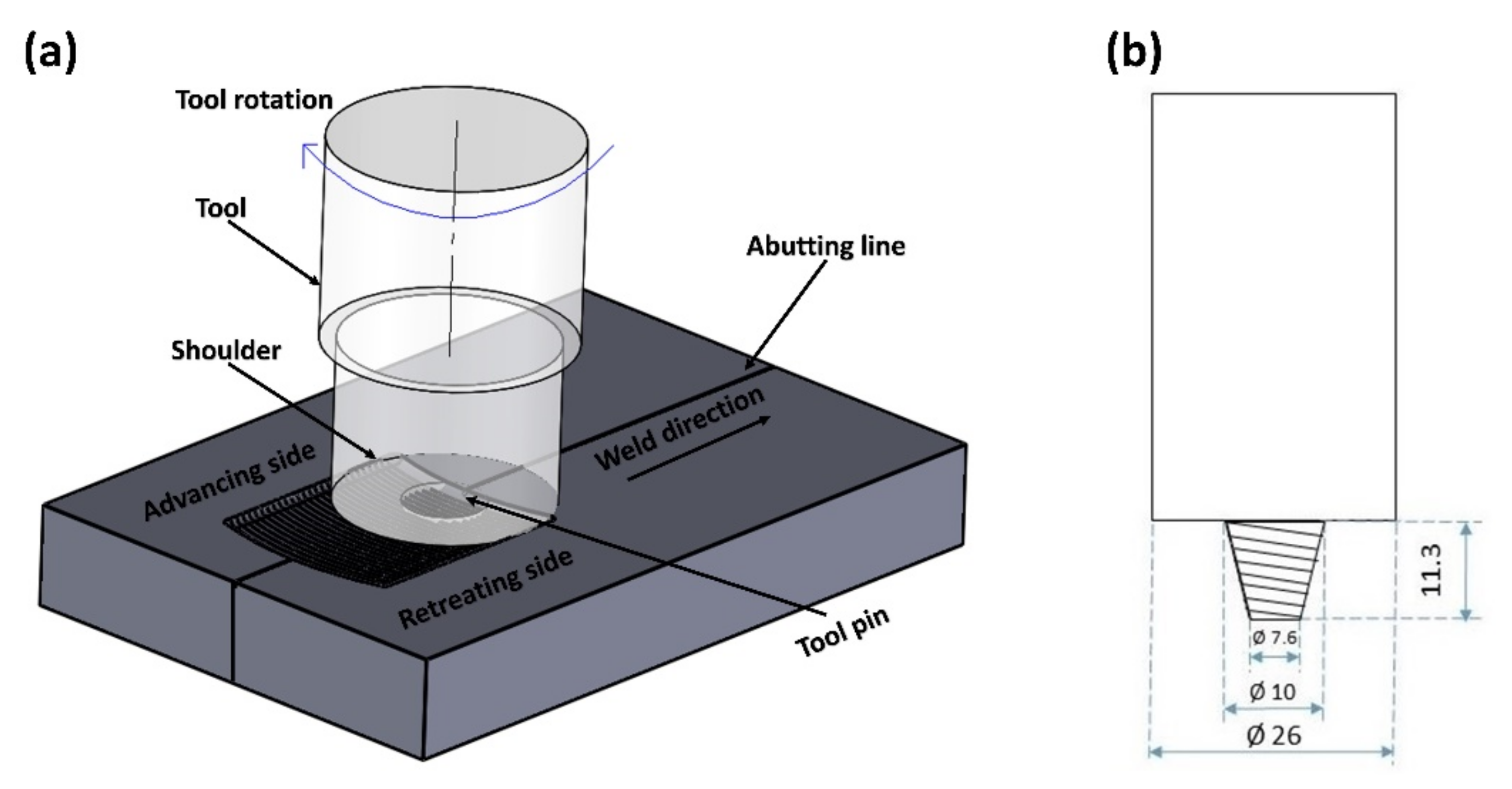
2. Materials and Methods
3. Results and Discussion
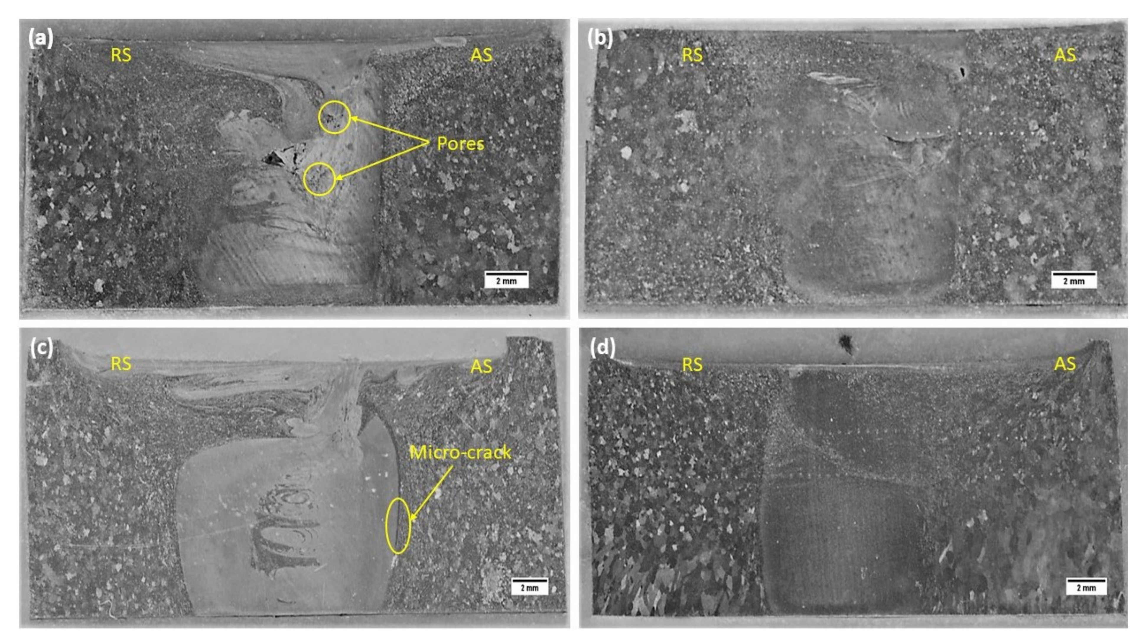
3.1. Macrostructure
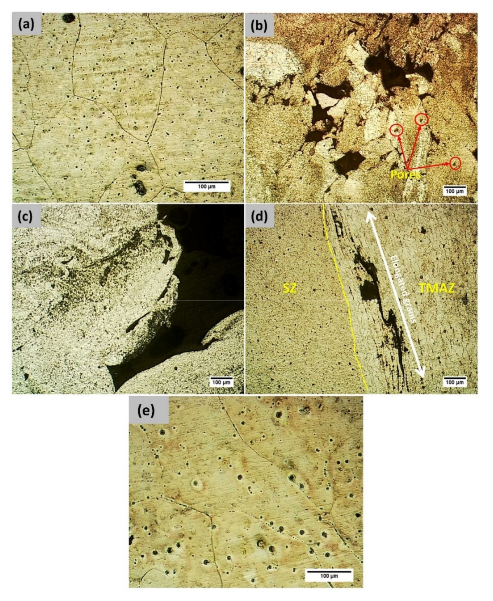
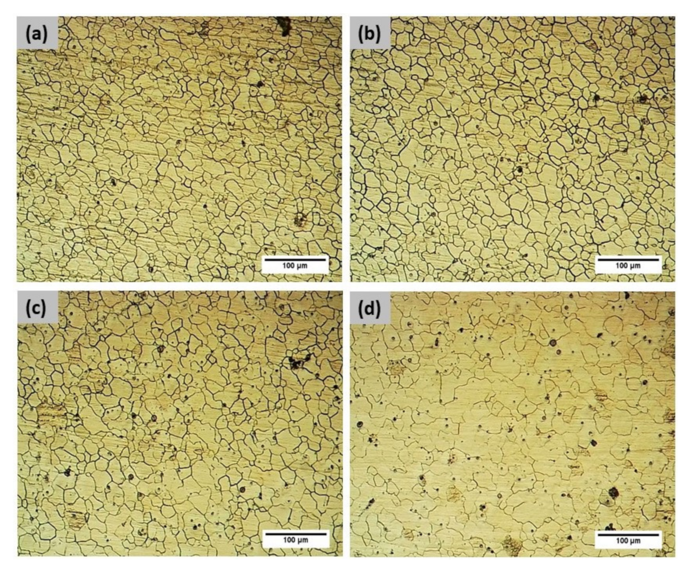
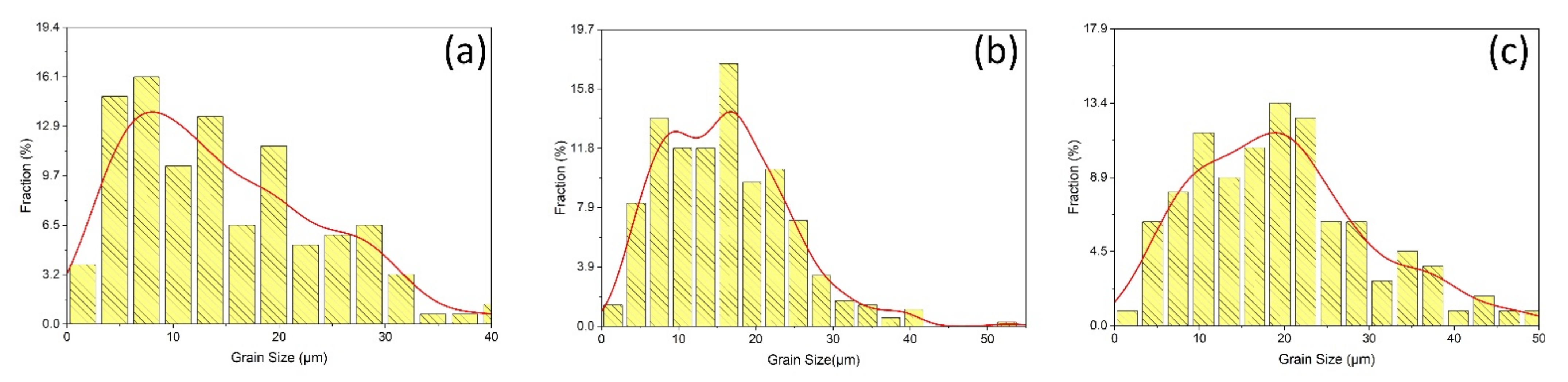
3.2. Microstructure
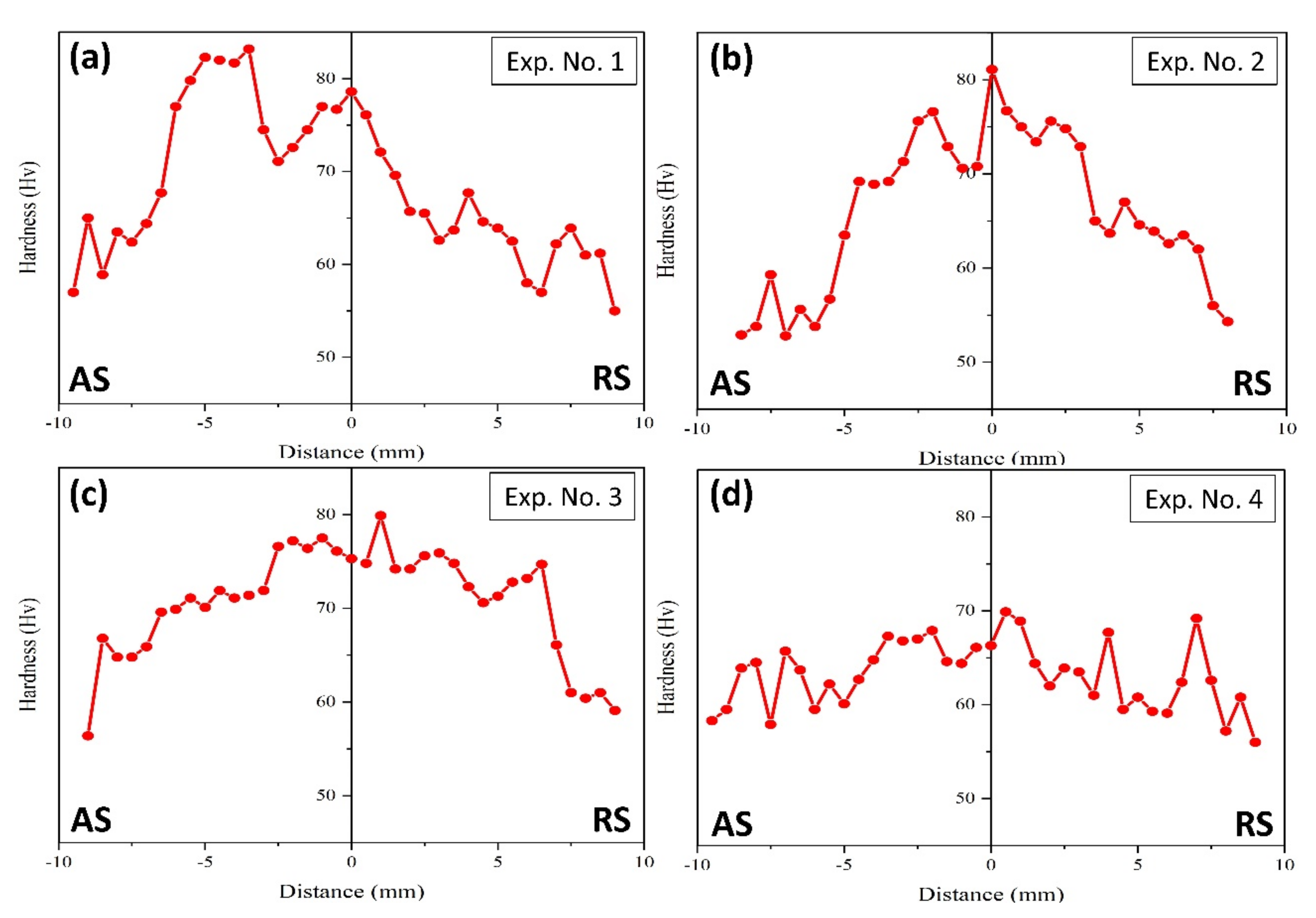
3.3. Micro-Hardness
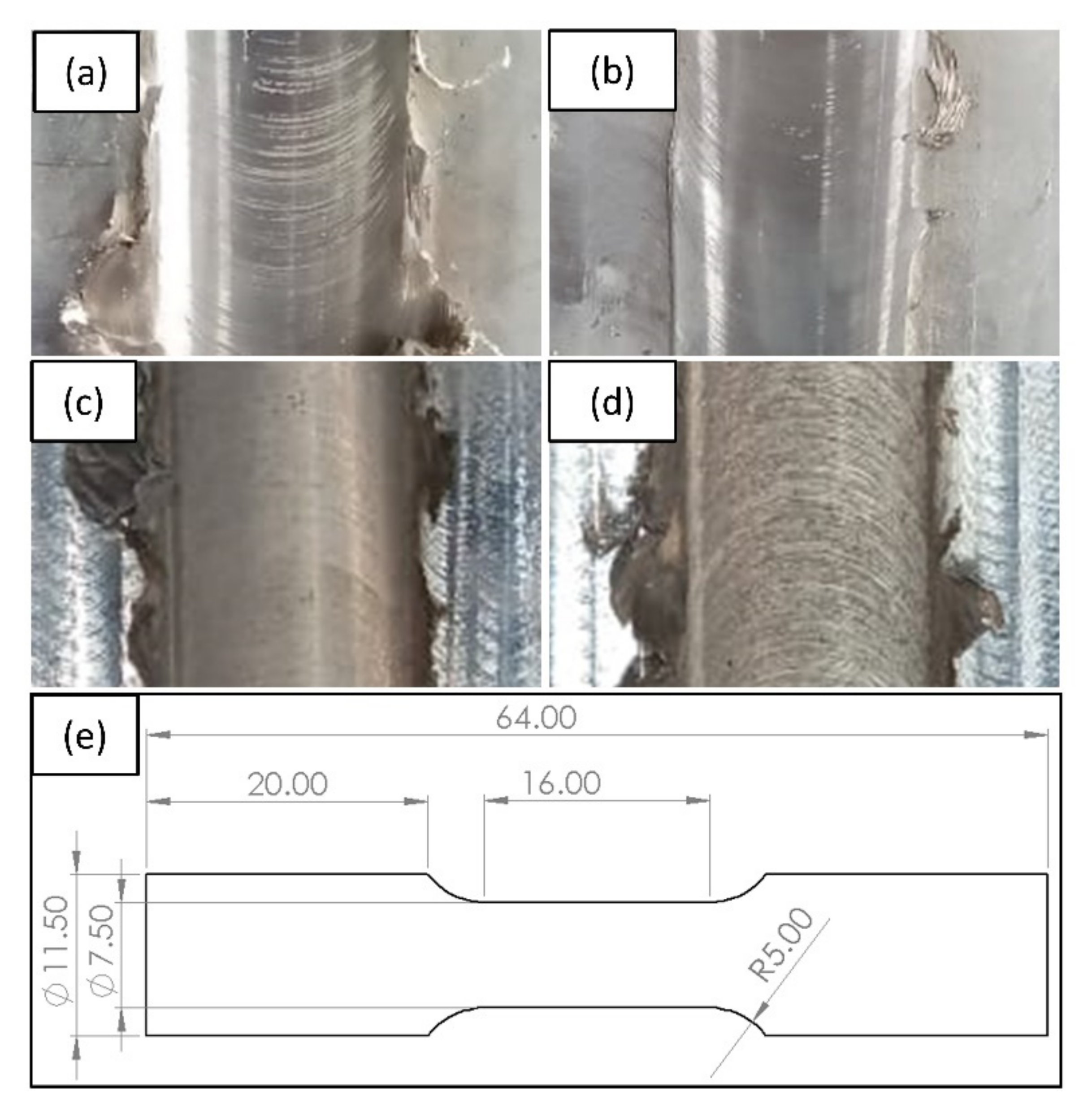
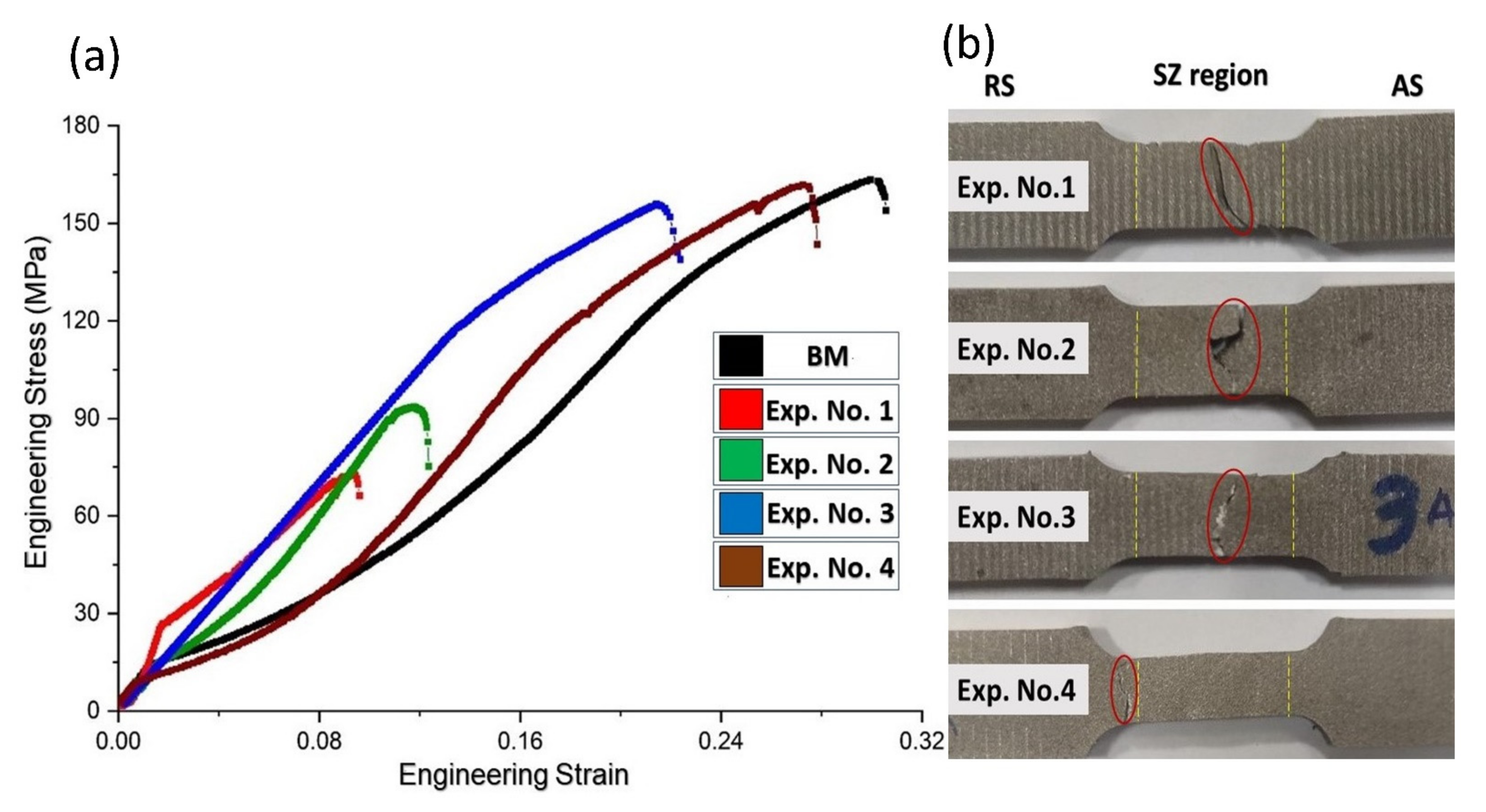
3.4. Tensile Strength
4. Conclusions
- The optimization of process parameters can eliminate the chances of tunneling defect formation due to improved material flow and consolidation.
- The grain refinement achieved in SZ is nearly 15 times the parent material, this is attributed to the degree of stirring and the tool profile used. An increase of 14.3% was achieved in the value of micro-hardness. Disparity in grain size distribution and grain modality across the stir zone leads to fluctuation in micro-hardness for the defect free weldment.
- A joint efficiency of 98.9% and elongation of 27.87% was achieved at a rotational speed of 710 rpm and traverse speed of 100 mm/min. The fracture occurred at the interface of HAZ and parent material for this weld, ascertaining the perfect weld formation in the nugget zone.
- Micro-crevices were observed at the SZ/TMAZ interface for tool rotational and traverse speeds of 560 rpm and 80 mm, respectively. In comparison to the tunneling defects, formation of these micro-crevices is far less detrimental to the strength of fabricated friction stir welds.
Author Contributions
Funding
Institutional Review Board Statement
Informed Consent Statement
Data Availability Statement
Conflicts of Interest
References
- Stoklosa, A. GM Moves toward Production Magnesium Body Panels. Available online: https://www.caranddriver.com/news/a18736670/gm-develops-new-thermal-forming-manufacturing-process-for-magnesium-sheet-metal/#:~:text=General%20Motors%20has%20announced%20that,than%20produced%20by%20the%20competition (accessed on 13 July 2021).
- Woodall, B. GM Tests Magnesium Sheet Metal to Take Weight out of Cars. Available online: https://www.reuters.com/article/us-gm-magnesium-idUSBRE89M0UP20121023 (accessed on 17 July 2021).
- Kamado, S. Strong, Light Weight, and Inexpensive “Magnesium Alloy”. Available online: https://www.jst.go.jp/EN/achievements/research/bt2020-09.html (accessed on 17 July 2021).
- Berge, F.; Ullmann, M.; Kittner, K.; Kawalla, R.; Vogt, H.-P. Application of Magnesium Sheets and Strips in Vehicle Construction. In Proceedings of the 4th AutoMetForm and 21st Sächsische Fachtagung für Umformtechnik (SFU), Freiberg, Germany, 3–5 November 2014. [Google Scholar]
- Song, K.; Pan, F.S.; Chen, X.H.; Zhang, Z.H.; Tang, A.T.; She, J.; Yu, Z.W.; Pan, H.C.; Xu, X.Y. Effect of texture on the electromagnetic shielding property of magnesium alloy. Mater. Lett. 2015, 157, 73–76. [Google Scholar] [CrossRef]
- Luo, A.A. Magnesium casting technology for structural applications. J. Magnesium Alloys 2013, 1, 2–22. [Google Scholar] [CrossRef] [Green Version]
- Dziubinska, A.; Gontarz, A. A new method for producing magnesium alloy twin-rib aircraft brackets. Aircraft Eng. Aerospace Technol. Int. J. 2015, 87, 180–188. [Google Scholar] [CrossRef]
- Song, J.; She, J.; Chen, D.; Pan, F. Latest research advances on magnesium and magnesium alloys worldwide. J. Magnes. Alloys 2020, 8, 1–41. [Google Scholar] [CrossRef]
- Singh, K.; Singh, G.; Singh, H. Review on friction stir welding of magnesium alloys. J. Mag. Alloys 2018, 6, 399–416. [Google Scholar] [CrossRef]
- Chi, C.-T.; Chao, C.-G. Characterization on electron beam welds and parameters for AZ31B-F extrusive plates. J. Mater. Process. Technol. 2007, 182, 369–373. [Google Scholar] [CrossRef]
- Marya, M.; Edwards, G.R. Factors controlling the magnesium weld morphology in deep penetration welding by a CO2 laser. J. Mater. Eng. Perform. 2001, 10, 435–443. [Google Scholar] [CrossRef]
- Ogawa, K.; Yamaguchi, H.; Ochi, H.; Sawai, T.; Suga, Y.; Oki, Y. Friction welding of AZ31 magnesium alloy. Weld. Int. 2003, 17, 879–885. [Google Scholar] [CrossRef]
- Rao, T.S.; Reddy, G.M.; Rao, S.K. Microstructure and mechanical properties of friction stir welded AA7075–T651 aluminum alloy thick plates. Trans. Nonferr. Metals Soc. China 2015, 25, 1770–1778. [Google Scholar] [CrossRef]
- Sabari, S.S.; Malarvizhi, S.; Balasubramanian, V.; Reddy, G.M. Experimental and numerical investigation on under-water friction stir welding of armour grade AA2519-T87 aluminium alloy. Def. Technol. 2016, 12, 324–333. [Google Scholar] [CrossRef] [Green Version]
- Ubaid, M.; Bajaj, D.; Mukhopadhyay, A.K.; Siddiquee, A.N. Friction stir welding of thick AA2519 alloy: Defect elimination, mechanical and micro-structural characterization. Metals Mater. Int. 2020, 26, 1841–1860. [Google Scholar] [CrossRef]
- Bajaj, D.; Siddiquee, A.N.; Mukhopadhyay, A.K.; Ali, N. The Effect of Tool Design on the Friction Stir Welding of Thick Aluminum Alloy AA6082-T651 Extruded Flats. Metallogr. Microstruct. Anal. 2020, 9, 841–855. [Google Scholar] [CrossRef]
- Xu, W.; Liu, J.; Luan, G.; Dong, C. Temperature evolution, microstructure and mechanical properties of friction stir welded thick 2219-O aluminum alloy joints. Mater. Design 2009, 30, 1886–1893. [Google Scholar] [CrossRef]
- Delijaicov, S.; Rodrigues, M.; Farias, A.; Neves, M.D.; Bortolussi, R.; Miyazaki, M.; Brandão, F. Microhardness and residual stress of dissimilar and thick aluminum plates AA7181-T7651 and AA7475-T7351 using bobbin, top, bottom, and double-sided FSW methods. Int. J. Adv. Manuf. Technol. 2020, 108, 277–287. [Google Scholar] [CrossRef]
- Sahu, P.K.; Pal, S. Mechanical properties of dissimilar thickness aluminium alloy weld by single/double pass FSW. J. Mater. Process. Technol. 2017, 243, 442–455. [Google Scholar] [CrossRef]
- Xu, W.F.; Luo, Y.X.; Fu, M.W. Microstructure evolution in the conventional single side and bobbin tool friction stir welding of thick rolled 7085-T7452 aluminum alloy. Mater. Charact. 2017, 138, 48–55. [Google Scholar] [CrossRef]
- Zhou, M.; Morisada, Y.; Fujii, H.; Ishikawa, T. Mechanical properties optimization of AZX612-Mg alloy joint by double-sided friction stir welding. J. Mater. Process. Technol. 2018, 254, 91–99. [Google Scholar] [CrossRef]
- Weng, F.; Liu, Y.; Chew, Y.; Lee, B.Y.; Ng, F.L.; Bi, G. Double-side friction stir welding of thick magnesium alloy: Microstructure and mechanical properties. Sci. Technol. Weld. J. 2020, 25, 359–368. [Google Scholar] [CrossRef]
- Mehta, K.P.; Badheka, V.J. A Review on Dissimilar Friction Stir Welding of Copper to Aluminum: Process, Properties, and Variants. Mater. Manuf. Process. 2016, 31, 233–254. [Google Scholar] [CrossRef]
- Xue, P.; Ni, D.R.; Wang, D.; Xiao, B.L.; Ma, Z.Y. Effect of friction stir welding parameters on the microstructure and mechanical properties of the dissimilar Al–Cu joints. Mater. Sci. Eng. A 2011, 528, 4683–4689. [Google Scholar] [CrossRef]
- Qian, J.; Li, J.; Sun, F.; Xiong, J.; Zhang, F.; Lin, X. An analytical model to optimize rotation speed and travel speed of friction stir welding for defect-free joints. Scripta Mater. 2013, 68, 175–178. [Google Scholar] [CrossRef]
- Mishra, R.S.; Ma, Z.Y. Friction stir welding and processing. Mater. Sci. Eng. R. Rep. 2005, 50, 1–78. [Google Scholar] [CrossRef]
- Albannai, A. Review the Common Defects in Friction Stir Welding. Int. J. Sci. Technol. Res. 2020, 9, 318–329. [Google Scholar]
- Seidel, T.U.; Reynolds, A.P. Visualization of the material flow in AA2195 friction-stir welds using a marker insert technique. Metall. Mater. Trans. A 2001, 32, 2879–2884. [Google Scholar] [CrossRef]
- Ali, M.; Anjum, S.; Siddiquee, A.N.; Khan, Z.A.; Chen, X.; Konovalov, S.; Anjum, A.; Shakeel, S.; Ibrahimi, H. Defect formation during dissimilar aluminium friction stir welded T-joints. Mech. Ind. 2020, 21, 205. [Google Scholar] [CrossRef]
- Commin, L.; Dumont, M.; Masse, J.E.; Barrallier, L. Friction stir welding of AZ31 magnesium alloy rolled sheets: Influence of processing parameters. Acta Mater. 2009, 57, 326–334. [Google Scholar] [CrossRef] [Green Version]
- Lone, N.F.; Mahmood, A.; Ashraf, A.; Alam, M.M.; Hussain, H.; Basu, S. Concomitant Outcomes due to the Alterations of Process Parameters During the Friction Stir Welding of T-Joint Between Dissimilar Aluminium Alloys. Int. J. Eng. Sci. 2020, 13, 50–57. [Google Scholar] [CrossRef]

| Elements (wt. %) | Mg | Y | Gd |
|---|---|---|---|
| 93% | 4% | 3% | |
| Mechanical Properties | Tensile Strength (MPa) | Micro-hardness (HV) | Elongation (%) |
| 163.5 | 60 | 30.56 |
| Experiment No. | 1 | 2 | 3 | 4 |
|---|---|---|---|---|
| Rotational Speed “ω” (rpm) | 710 | 560 | 560 | 710 |
| Traverse Speed “V” (mm/min) | 80 | 100 | 80 | 100 |
Publisher’s Note: MDPI stays neutral with regard to jurisdictional claims in published maps and institutional affiliations. |
© 2021 by the authors. Licensee MDPI, Basel, Switzerland. This article is an open access article distributed under the terms and conditions of the Creative Commons Attribution (CC BY) license (https://creativecommons.org/licenses/by/4.0/).
Share and Cite
Moiduddin, K.; Siddiquee, A.N.; Abidi, M.H.; Mian, S.H.; Mohammed, M.K. Friction Stir Welding of Thick Plates of 4Y3Gd Mg Alloy: An Investigation of Microstructure and Mechanical Properties. Materials 2021, 14, 6924. https://doi.org/10.3390/ma14226924
Moiduddin K, Siddiquee AN, Abidi MH, Mian SH, Mohammed MK. Friction Stir Welding of Thick Plates of 4Y3Gd Mg Alloy: An Investigation of Microstructure and Mechanical Properties. Materials. 2021; 14(22):6924. https://doi.org/10.3390/ma14226924
Chicago/Turabian StyleMoiduddin, Khaja, Arshad Noor Siddiquee, Mustufa Haider Abidi, Syed Hammad Mian, and Muneer Khan Mohammed. 2021. "Friction Stir Welding of Thick Plates of 4Y3Gd Mg Alloy: An Investigation of Microstructure and Mechanical Properties" Materials 14, no. 22: 6924. https://doi.org/10.3390/ma14226924
APA StyleMoiduddin, K., Siddiquee, A. N., Abidi, M. H., Mian, S. H., & Mohammed, M. K. (2021). Friction Stir Welding of Thick Plates of 4Y3Gd Mg Alloy: An Investigation of Microstructure and Mechanical Properties. Materials, 14(22), 6924. https://doi.org/10.3390/ma14226924