Article

Synthesis and Characterization of Activated Carbon Co-Mixed Electrospun Titanium Oxide Nanofibers as Flow Electrode in Capacitive Deionization

Institut Européen des Membranes, IEM, UMR-5635, Université de Montpellier, ENSCM, CNRS, Place Eugène Bataillon, CEDEX 5, 34095 Montpellier, France
*
Authors to whom correspondence should be addressed.
Materials 2021, 14(22), 6891; https://doi.org/10.3390/ma14226891
Submission received: 6 October 2021 / Revised: 8 November 2021 / Accepted: 9 November 2021 / Published: 15 November 2021
(This article belongs to the Topic Electromaterials for Environment & Energy)

Abstract

:
Flow capacitive deionization is a water desalination technique that uses liquid carbon-based electrodes to recover fresh water from brackish or seawater. This is a potential second-generation water desalination process, however it is limited by parameters such as feed electrode conductivity, interfacial resistance, viscosity, and so on. In this study, titanium oxide nanofibers (TiO2NF) were manufactured using an electrospinning process and then blended with commercial activated carbon (AC) to create a well distributed flow electrode in this study. Field emission scanning electron microscope (FESEM), X-ray diffraction (XRD), Raman spectroscopy, X-ray photoelectron spectroscopy (XPS), and energy dispersive X-ray (EDX) were used to characterize the morphology, crystal structure, and chemical moieties of the as-synthesized composites. Notably, the flow electrode containing 1 wt.% TiO2NF (ACTiO2NF 1 wt.%) had the highest capacitance and the best salt removal rate (0.033 mg/min·cm2) of all the composites. The improvement in cell performance at this ratio indicates that the nanofibers are uniformly distributed over the electrode’s surface, preventing electrode passivation, and nanofiber agglomeration, which could impede ion flow to the electrode’s pores. This research suggests that the physical mixture could be used as a flow electrode in capacitive deionization.

1. Introduction

One of the growing challenges of the 21st century is the availability of fresh water. Water contamination because of anthropogenic activities such as industrialization, demographic change, and global warming has resulted in a significant increase in demand for safe drinking water. Water desalination technology could help to alleviate this problem by delivering high quality, pure water. Most desalination technologies, such as multiple effect desalination (MED), reverse osmosis (RO), and others, have high capital costs (when considering plant setup) and energy consumption (when considering pre- and post-treatment of water, as in RO), necessitating the development of a new desalination technique [1].
Capacitive deionization (CDI) is a growing desalination technology attracting attention as an energy-efficient, cost-effective, and ecofriendly water treatment technology. The first and most widely used CDI form involves a pair of porous carbon electrodes separated by a space in which salt water flows as an influent perpendicular to the applied electric field direction [2]. A fundamental variation of this basic CDI form emerged with the unfolding of membrane CDI (MCDI). In this architecture, ion exchange membranes were added to the CDI cell configuration to block co-ions from carrying parasitic current, which improves charge efficiency and can increase the charge storage in the electrodes porous structure [3]. In the past decade, a new class for CDI based on MCDI was developed which introduced carbon flow electrodes that can be pumped through the electrode compartments. Flow electrode CDI (FCDI) is a promising second-generation water desalination method based on the principle of ions adsorption. When a specific voltage is applied, it entails using a polarized flow electrode (liquid electrode) travelling via a flow channel to adsorb ions from brackish or seawater via electrical double layer (EDL) formation (interface between electrolyte and electrode) [4].
One of the challenges in FCDI is to improve the conductivity and capacitance of carbon materials used as electrodes, as well as reducing the resistance between the electrode and the electrolyte. This can be accomplished by improving the surface charge of activated carbon for better EDL formation [5].
Because of its beneficial qualities such as high surface area, porosity, availability, and low cost, graphitic carbon, materials such as activated carbon are frequently used as flow electrodes [6,7]. However, for more effective EDL formation and better ion storage, the resistance at the electrode-electrolyte interface should be lowered. As a result, surface modification is required to raise the surface charge of activated carbon.
Metal oxides such as zinc oxide (ZnO), tin oxide (SnO), zirconium oxide (ZrO), and titanium oxide (TiO2) have been used to modify carbon in this concept [8,9]. Among all these oxides, TiO2 has a high surface charge that can be used in conjunction with AC to create new types of electrodes. The aggregation of TiO2 particles, however, is one of the additive’s downsides, limiting its performance [10,11,12]. Small quantities of TiO2 nanofibers are used in activated carbon flow electrodes to alleviate the agglomeration problem since they have a favorable large axial ratio morphology [13,14].
Due to the high resistance of the liquid medium utilized for carbon dispersion for slurry formation, charge transfer resistance is a strong factor hindering the ease of ions diffusion into the pores of carbon electrodes in flow electrodes [15]. As a result, methods for reducing interfacial resistance by adding conducting additives or introducing oxygenated functional groups to activated carbon have been reported in the literature [15,16,17,18], but no report on the properties of TiO2 nanofibers in reducing interfacial resistance and their effect on the rheological properties of carbon-based flow electrodes has been found to date.
Nanofiberous materials of high surface area and porosity are considered recently to be used for generating sustainable and green energy resources. Electrospinning method is a low-cost method used to create nanofiberous materials suited for many energy-related applications such as supercapacitors, and Li-ion batteries [19,20].
Motivated by this, we have synthesized TiO2 nanofibers by electrospinning process and mixed it with commercial AC. The proposed electrodes which consisted of different weight percentage of TiO2NF were labelled TiO2NF-x where x represents the weight percentage of TiO2NF in the composite (x = 0.5, 1.0, 1.5, 2.0, 2.5, and 5.0 wt.% TiO2NF). The electrodes were characterized by FESEM, XRD, Raman spectroscopy, XPS, EDX, and N2 adsorption/desorption. Dynamic viscosity of the mixtures in suspension to build the flow electrodes was also investigated. Hence, the electrochemical properties of the as-prepared flow electrodes (AC and TiO2NF-x) were analyzed by cyclic voltammetry (CV) to determine their capacitance after which the flow electrodes were tested in a laboratory-made FCDI cell for desalination.

2. Materials and Methods

2.1. Materials

Activated carbon, Darco (CAS no: 7440-44-0, MW 12.01 g mol−1), titanium (IV) isopropoxide (C12H28O4Ti, CAS no: 546-68-9, MW 284.22 g mol−1, 97%), poly(vinyl pyrrolidone) (PVP, CAS no: 9003-39-8, MW 1,300,000 g mol−1), and sodium chloride (NaCl, CAS no: 7647-14-5, MW 58.44 g mol−1, 99%) were obtained from Sigma Aldrich, Steinheim, Germany. Acetic acid (CH3COOH MW 60.052 g mol−1, 99.5% assay), absolute ethanol (C2H5OH MW 46.07 g mol−1, 99.99%,) were obtained from VWR chemicals, Fontenay-sous Bois, France. Polyvinylidenefluoride (PVDF) (CAS no: 24937-79-9) was obtained from Alfa Aesar, Erlenbachweg 2, Kendel, Germany. All reagents were used without any further purification. Cationic and anionic exchange membranes were purchased from Membranes International Inc. (Ringwood, NJ, USA) and Deionized water (18 MΩ·cm) was used to prepare standard solutions and suspensions.

2.1.1. Synthesis of TiO2 Nanofibers by Electrospinning

The TiO2 nanofibers were synthesized by electrospinning technique. Briefly, solution A containing 3 mL of ethanol was added to 0.3 g of polyvinyl pyrrolidone (PVP) and then stirred until dissolution. Then, solution B consisting of 2 mL ethanol, 2 mL of acetic acid, and 3 mL of titanium isopropoxide was stirred for 45 min. This is then followed by the addition of solution B into clear solution of A and then further stirred for 50 min to obtain a sol gel solution. Electrospinning of the sol–gel solution was carried out at 22.30 kV. The distance between the collector and the syringe tip was maintained at 10 cm, and the injection speed was 0.5 mL min−1. The obtained electrospun nanofiber materials were sintered in air atmosphere at 400 °C for 4 h with a ramp rate of 1 °C min−1.

2.1.2. Preparation of AC and ACTiO2NF–x Flow Electrodes

For flow electrode preparation, certain amount of powdered commercial AC and ACTiO2NF-x (in which x corresponds to 1.0, 1.5, 2.0, 2.5, and 5.0 wt.% of TiO2NF) were weighed and dispersed in deionized water as presented in Table 1. The mixtures were sonicated for 3 h and stirred for 1 h before being fed into the cell. The tank containing the slurry electrode was continuously stirred on a magnetic stirrer during the course of the experiment.

2.2. Physical Characterization

FESEM was used to analyze the morphology of the samples (Hitachi S4800, Tokyo, Japan). The structural properties were studied by using Raman spectroscopy (HORIBA Xplora, Tokyo, Japan) and XRD (Pan Analytical X’pert Phillips, Almelo, The Netherlands). XPS (ESCALAB 250 Thermo Electron, Montigny Le Bretonneux, France) and EDX (X-Max, Oxford, UK) were used to investigate the atomic composition and chemical moieties of the materials. For the XPS analysis, the excitation source was a monochromatic source Al Kα anode with photoenergy that was observed at 1486.6 eV. The analyzed surface has a diameter of 500 µm. The photoelectron spectra were calibrated in terms of bond energy with respect to the energy of the C=C component of carbon C1s at 284.4 eV. Surface area was obtained by using N2 adsorption/desorption at 77 K (Micromeritics ASAP, Verneuil en Halatte, France). Dynamic viscosity was measured using Anton Paar Rheometer Physica MCR 301 (Anton Paar, Graz, Austria).

2.3. Electrochemical Characterizations

Solid electrodes for electrochemical characterization of pristine AC and ACTiO2NF were made by combining activated carbon powder (0.32 g), carbon black (0.04 g), and poly (vinylidene fluoride fluoride PVdF, 0.04 g) in 3 mL N-Methyl-2-pyrrolidone (NMP). To establish homogeneity, the mixture was agitated for 2 h and then sonicated for 40 min. After that, the slurry was applied on a graphite sheet. The coated electrode was dried in an oven for 1–2 h at 80 °C. The as-synthesized titanium oxide nanofibers were added (0.5, 1.0, 1.5, 2.0, 2.5, and 5.0 wt.%) to AC containing carbon black and PVDF, and the mixture was agitated for several hours in 3 mL NMP for ACTiO2NF synthesis. After that, the mixture was sonicated for 40 min. The slurry was subsequently immobilized by depositing it on a graphite sheet. It was then dried in an oven at 80 °C for 1–2 h to produce solid electrodes.
The electrochemical properties of the prepared electrodes were examined by using CV. CV tests were performed using a three-electrode system. The mixtures were deposited on a graphite sheet as support with an exposed surface area of 1 cm2, while a platinum mesh and a saturated 3 M KCl, Ag/AgCl electrode served as counter and reference electrodes respectively. A molar NaCl solution was used as electrolyte. Voltammetry measurements were performed with Origalys potentiostat (OGF01A, Origalys Electrochem SAS, Rillieux-la-Pape, France) at an operating window from −0.4 to 0.6 V vs ref (to ensure electrochemical stability of the electrolyte and prevent water splitting i.e., oxygen and hydrogen evolution) in 1 M NaCl electrolyte.
The double-layer capacitance was determined using cyclic voltammetry at different scan rates by considering the charging and the discharging currents at 0.1 V vs. ref. The determined double-layer capacitance of the system was the average of the absolute value of the slope of the linear plot of charging and discharging currents fitted to the data. CDL as the double layer capacitance was determined using Equation (1):
i = υ CDL.
The double-layer charging current density i (A·cm−2) is equal to the product of the scan rate υ (V·s−1), and the electrochemical double-layer capacitance CDL (F·cm−2).

2.4. FCDI Measurement

The schematic diagram of the close loop experimental set-up is shown in Figure 1 in which the cell was powered by a potentiostat and the feed solution (FS, 5 g·L−1) was made to pass through a spacer sandwiched in between cation and anion exchange membranes. The feed electrodes (FE) stored in a reservoir (were made to pass (by pumping) through flow channels and as they exit the channels, they are fed back to the reservoir and then re-circulated; this allows co-mixing of opposite charged ions outside the cell. Figure 2 shows the breakdown of the cell components with the current collector (6 mm width and 0.9 mm depth channel), the ions exchanges membranes and spacer (0.9 mm thick). The flow rate of the electrodes was operated at 40 mL min−1. Each desalination experiment was conducted for 30 min. The initial conductivity of the salt solution and that of the effluent was monitored at room temperature by ion conductivity meter (Hanna Instruments SRL) all along the 30 min of the experiment. A constant voltage difference of 1.2 V was applied to the FCDI unit cell using an Origalys potentiostat (OGF01A, Origalys Electrochem SAS) for desalination experiments. The current intensity passing through the FCDI unit cell was consequently measured by the potentiostat during the experiment.
In the present work, the following indicators defined FCDI performances:
Salt removal rate in mg·min−1·cm−2 (SRR) relates to the mass of salt adsorbed (mg) per FE-FS contact area (cm2) per unit of time (min). It is calculated by Equation (2):
SRR = ( Co Cf ) V A t
Co and Cf are the initial and final (at t = 30 min) concentration (mol·L−1), respectively, V is the volume of the solution (L), A is the contact area between FE: FS, and t is the charging time.
The salt removal efficiency in % (SRE) was calculated using Equation (3):
SRE = ( Co Cf ) Co 100
Charge efficiency (CE) in % which relates to the ratio of salt adsorbed to the quantity of charge passed into the system was calculated by Equation (4):
CE = z   ( Co Cf )   V   F M   I d t 100
where z is the equivalent charge of the ions, F is the Faradaic constant, M is the molar weight, and ∫Idt is the integrated quantity of charge passed to the system as a function of time. CE is a good indicator for the energy efficiency of the system and will directly affect the operating cost of the system (OPEX).

3. Results and Discussion
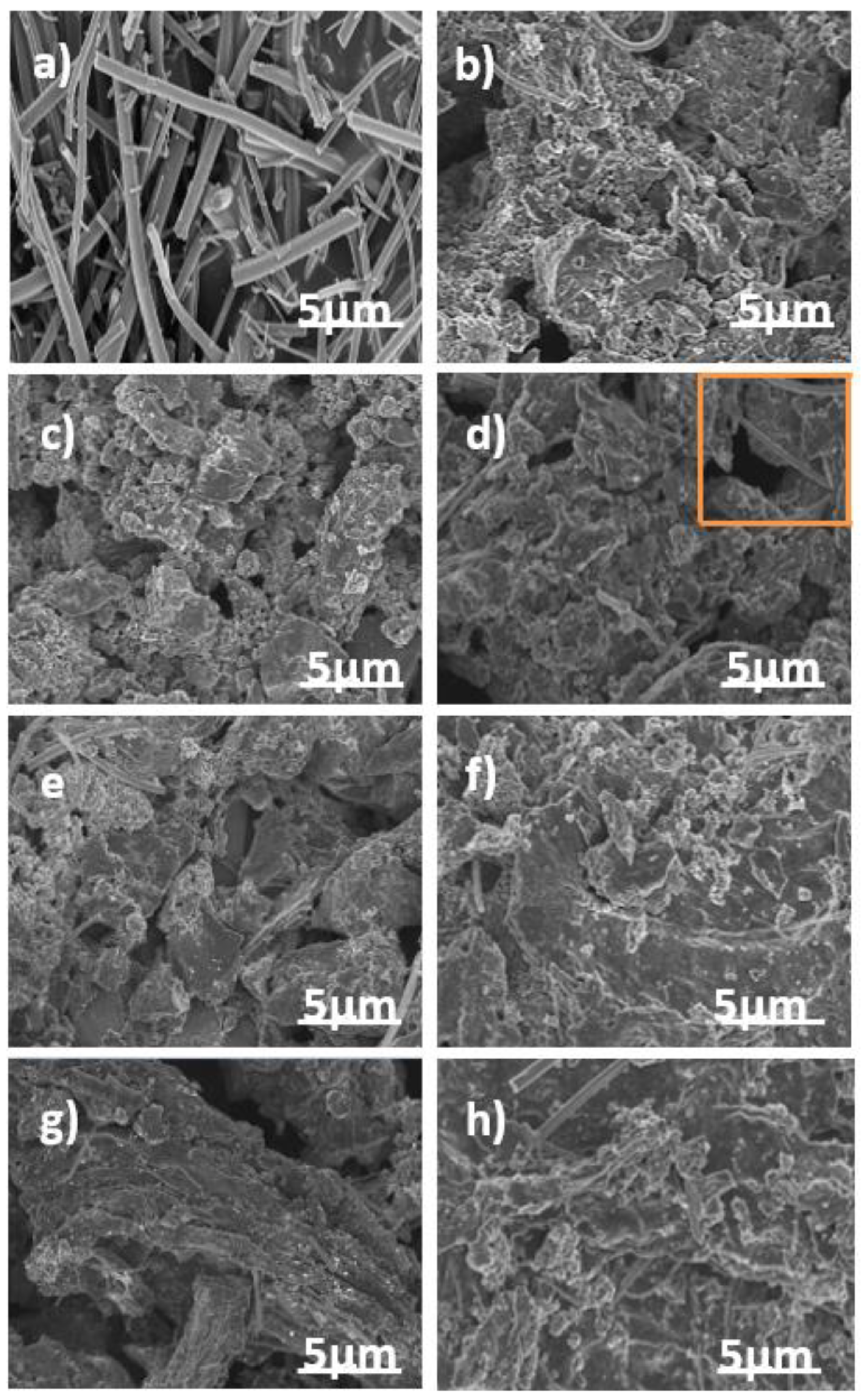
3.1. Morphology

The morphology of as-synthesized titanium oxide nanofibers (TiO2NF), pristine AC, and the ACTiO2NF-x electrodes are shown in Figure 3a–h respectively. From Figure 3a, it is apparent that the electrospun TiO2 showed fiber-like morphology with no beads formation. This shows the successful nanofibrous morphology of TiO2 formation by electrospinning process. Figure 3b shows the morphology of pristine AC. It is clear that it has no defined shape with rough or uneven surface characteristics while Figure 3c–h reveals the presence of TiO2NF on the surface of AC, indicating that the additive was successfully introduced by co-mixing.

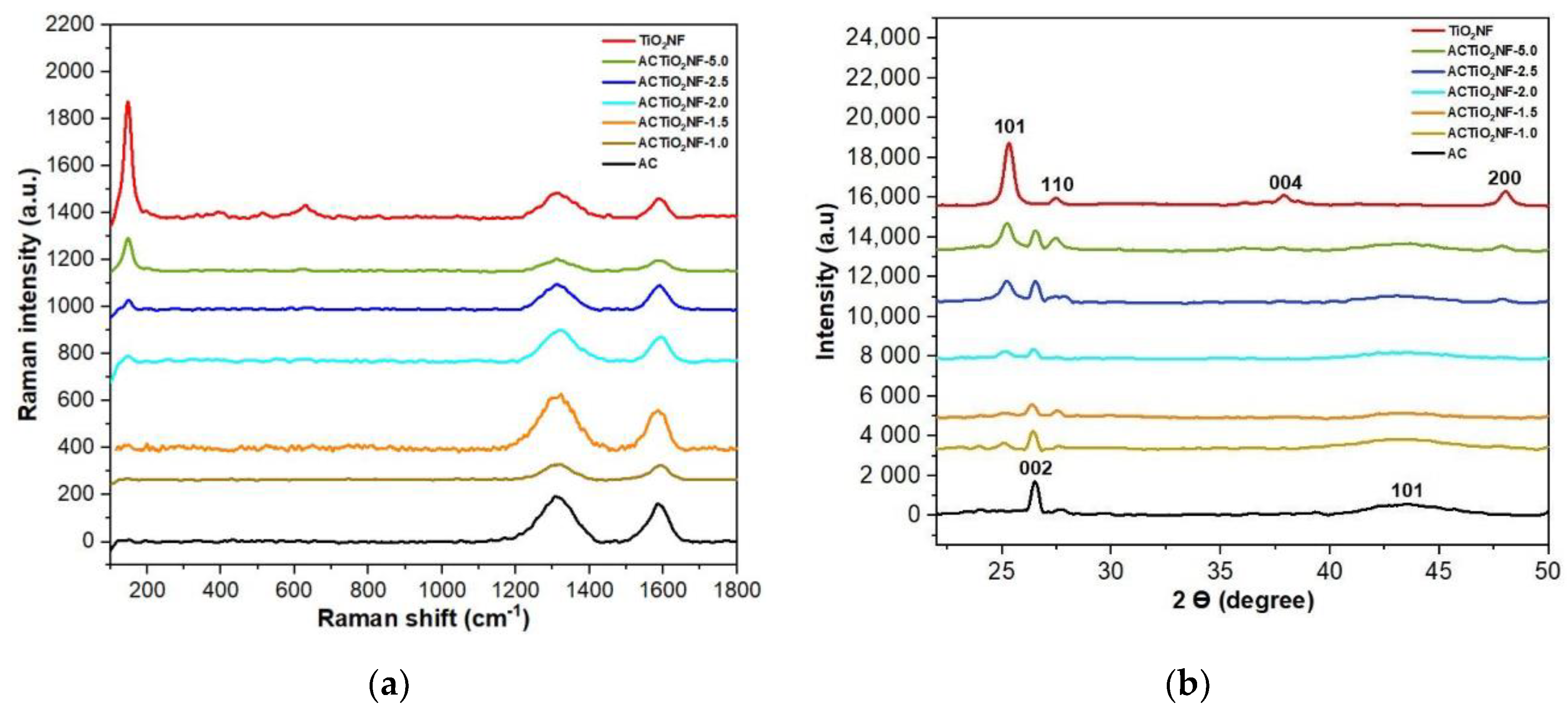
3.2. Structural Properties

Figure 4a,b shows the Raman spectra and diffractogram of the TiO2NF, pristine AC and ACTiO2NF s respectively. The Raman spectrum of the pristine AC and ACTiO2NF in Figure 4a conforms to a typical graphitic carbon with distinguishable peaks at 1350 cm−1 and 1590–1610 cm−1 corresponding to D and G bands respectively [21]. D band arises from a defect that is based on out of plane vibration while G band relates to the ordered structure of graphite crystals [13]. For the as-synthesized TiO2NF, Figure 4a, major peaks are observed at 142, 388, 516, and 638 cm−1 indicating anatase phase characteristics [8]. Distinguishable peaks of TiO2NF were observed in some of the composites especially for those with high percentage of TiO2NF as shown in Figure 4a. This indicates the successful mixing of the nanofibers with the AC.
Structural investigation was carried out to understand the crystalline nature of the materials. Figure 4b shows the diffractogram of pure TiO2NF, pristine AC, and its composites. The TiO2NF crystals are predominantly dominated with definite and sharp diffraction peaks at 2θ = 25°, 39° and 43.5° relating to 101, 004, and 200 planes of anatase phase respectively with the presence of rutile phase at 2θ = 27.5°, 36°, and 41° relating to 110, 101, and 111 planes respectively [8]. Typical diffraction peaks of all graphite material is observed for pristine AC and ACTiO2NF at 2θ = 26° and 43.5 ° corresponding to 002 and 100 or 101 planes of graphite respectively. The sharp diffraction peaks observed at 002 planes indicates the presence of graphite microcrystalline structure in the AC [13]. In comparison with pristine AC, peaks of TiO2NF were detected at 25°, 27.5°, and 48° diffraction peaks of TiO2NF in all the composites thus showing successful doping of the nanofibers in the AC. Furthermore, using Debye-Scherrer equation, (D = Kλ/β, cosθ) where K is the constant value of 0.9, λ is the radiation of the XRD machine (0.1541 nm), β is the full width at half maximum of the diffraction peak in radian, and θ is the diffraction angle in radian, no changes were observed in the crystallite size (10 ± 0.830 nm) of the as-synthesized TiO2 nanofibers and ACTiO2NF.

3.3. EDX and XPS Studies

Figure 5a,b shows the EDX spectra that were obtained in order to identify the composition of the pristine AC and the composite electrode. Evidently from EDX, the elements detected at highest percentage in our materials are C and O. Titanium was detected among other elements in little quantity in the composite as shown in Figure 5b. The presence of fluorine was also detected due to the addition of PVDF (binder) added during electrode fabrication. Moreover, EDX mapping was further used to investigate the distribution of the additive in the mixture. From Figure S1a,b it can be seen that the additive distribution at lower concentration (1 wt.%) is homogenous (even dispersion) while at higher concentration (5 wt.%), its distribution is concentrated within a particular region. The results confirm the formation of well-dispersed nanofibrous within the carbon structure at low percentage concentration.
Further investigation was carried out using XPS in order to verify any change in the chemical composition of the pristine AC and its composites. Figure 5c shows two prominent peaks at 458.69 and 464.44 eV belonging to Ti 2P3/2 and Ti 2P1/2 respectively [22,23]. From Figure 5c, it is shown that Ti (IV) is present in normal state in the composites due to the observed spin orbital splitting corresponding to 5.76 eV that is obtained between Ti 2P1/2 and Ti 2P3/2. [23]. As shown in Figure 5d, no titanium was detected in the XPS spectra survey scan of the pristine AC on comparison with ACTiO2NF; a complementary result with that of EDX. The O1s peak in the composite increased a little bit when compared to pristine AC due to the influence of oxygen content of the additive. According to XPS, the atomic composition of the ACTiO2NF-1.0 consisted of C1s 90.6 ± 0.11%, O1s 7.9 ± 0.12%, and Ti 2p 1.0 ± 33.33% while that of pristine AC is C1s 94 ± 0.84% and O1s 5 ± 3.84%.

3.4. Rheology Study

Rheology property reveals the flow nature of the slurry used under applied force. The viscosity nature of the slurry electrode was measured as a function of shear rate. Here, rheology property is in terms of dynamic viscosity, which is used to describe resistance to flow of liquid while shear rate describes the speed of deformation of the slurry under applied force. The dynamic viscosity was determined at a constant concentration of 10 wt.% carbon content in the slurry. From Figure 6a, it is obvious that the slurry follows a non-Newtonian fluid (shear thinning effect) in which the viscosity of the slurries decreases with increasing shear rate. To understand the effect of the additive, the viscosities of both pristine AC and the ACTiO2NF mixture were measured and compared as shown in Figure 6a. It is obvious from the rheogram curves that viscosity increases as the additive content increases in the composite. However, at low percentage of additive, there seems to be no significant difference in the viscosities of both the pristine AC and the ACTiO2NF mixture but at i.e., TiO2NF ≥ 2.0 wt.%, a sharp increase in viscosity was observed. The increase in viscosity can be attributed to the high specific surface area (increase frictions) of titanium nanofibers as well as its surface charge. The surface charge of the nanofibers (whether positive or negative) leads to creation of repulsive forces existing within the nanoparticles and as a result, they tend to move further apart due to strengthened force of repulsion; consequently, viscosity increases with increasing repulsive forces [24,25,26,27,28]. Therefore, as the concentration of the additive in the electrodes increases, a distinguishable jump in their viscosity was observed due to increase in force of repulsion as shown in Figure 6b. This implies that the presence of additive at high content level could lead to potential clogging of the feed electrodes in the cell.

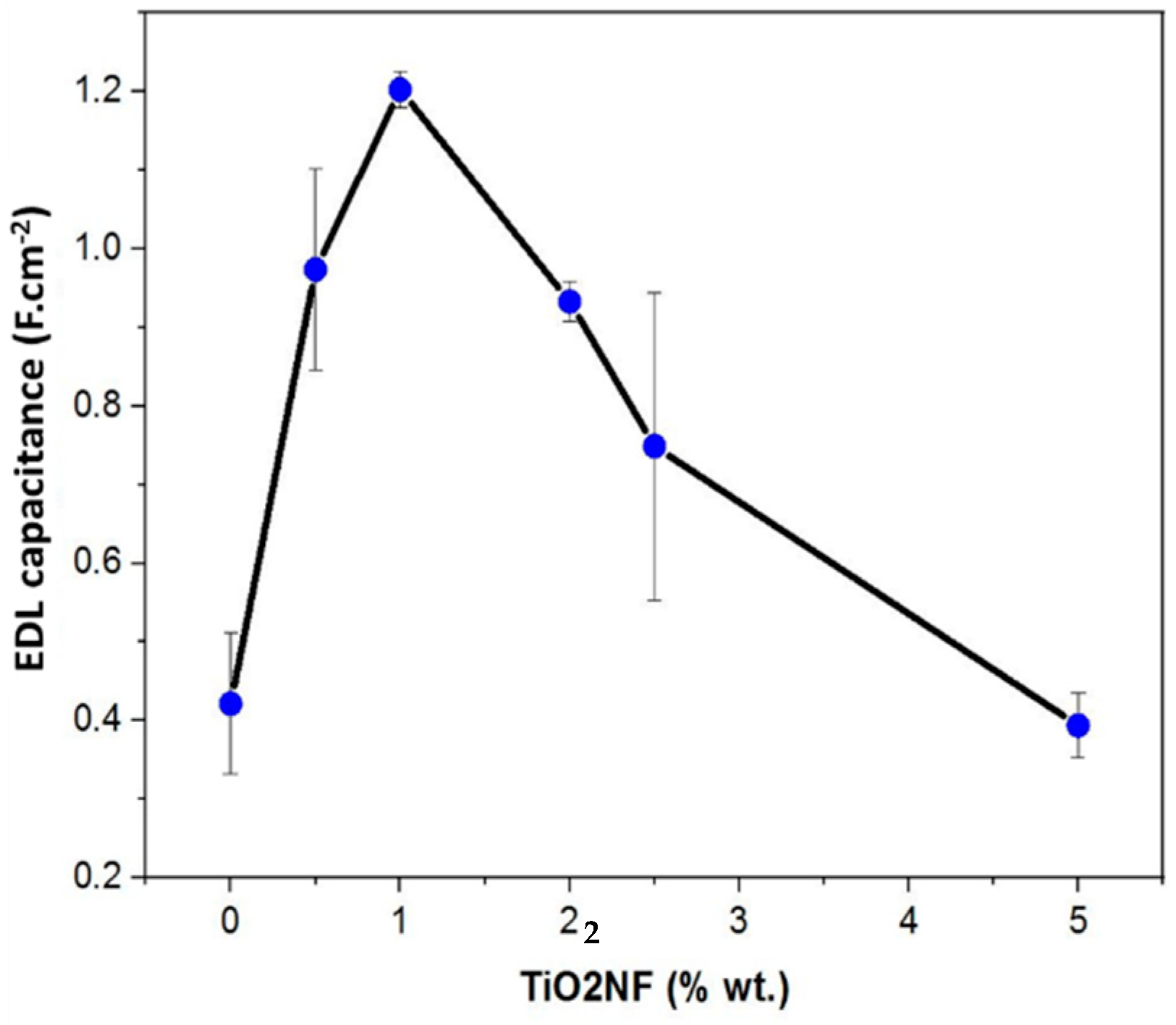
3.5. Electrochemical Properties

Electrochemical behavior of the pristine AC electrode and ACTiO2NF electrodes were carried out using CV at different scan rates in a potential window from −0.4 to 0.6 V vs. Ref (to ensure electrochemical stability of the electrolyte and prevent water splitting i.e., oxygen and hydrogen evolution). The experiment was conducted in 1 M NaCl aqueous solution to investigate the influence of the additive at different ratios. CV is an important technique to probe the capacitive nature of EDL [29,30].
Based on the cyclic voltammetry cycles, the EDL capacitance of the electrodes was calculated [31] and is shown in Figure 7.
Thus, incorporating TiO2NF at low rate into our carbon material enhances its double layer capacitance due to the formation of a uniform network distribution of TiO2 nanofibers between AC particles. However, as the presence of TiO2NF increases in the composite, there seem to be exhibition of poor electrochemical behavior possibly due to the increase in resistance to easy flow of ions into the pores of the electrode because of TiO2NF agglomeration [14]. Our results correlate to the findings reported in literature [8,14].

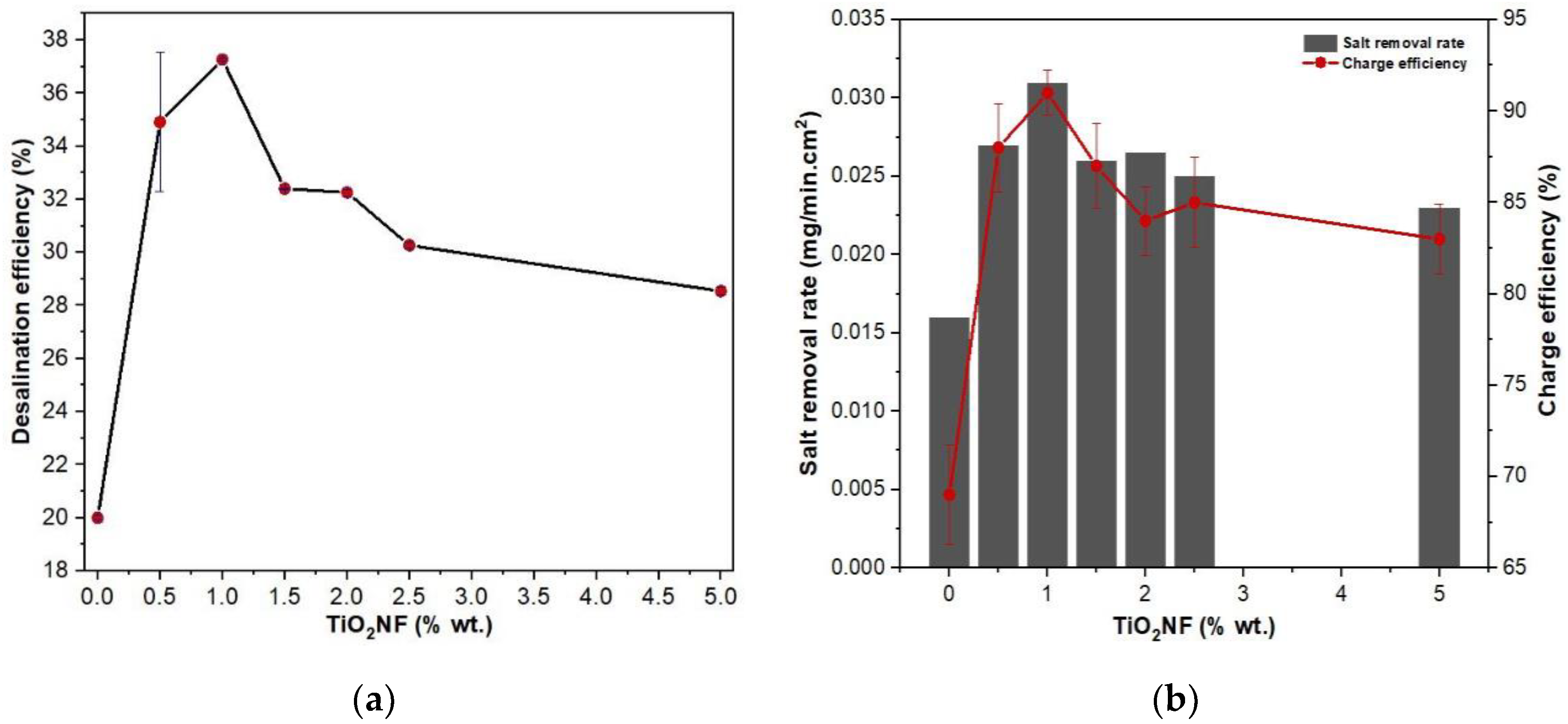
3.6. Desalination Performance

As reported in literature, the electrosorption performance of carbon-based materials is linked to their capacitive properties amid other factors [9,29]. As explained earlier, TiO2NF was added at different wt.% to influence the capacitance of commercial AC and this factor was verified through the electrochemical characteristics of the electrodes. Furthermore, in order to confirm the link between electrosorption performances and capacitive properties, desalination experiments were carried out under a semi-continuous system in a flow channel. Desalination was conducted at an operational cell potential ΔE = 1.2 V for 30 min using 5000 mg·L−1 NaCl as the feed solution. Difference in conductivity was monitored and recorded during the experiment. FCDI performance indicators such as desalination efficiency (DE) in Figure 8a, salt removal rate (SRR), and charge efficiency (CE) in Figure 8b were used to evaluate the performance of the flow electrodes.
Important increase in DE is noticed in Figure 8a. Notably, the ACTiO2NF electrodes show higher DE than pristine AC and among all the electrodes, ACTiO2NF-1.0 exhibited the best DE, which implies fast ion mobility to the pores of the flow electrode thus leading to quick salt removal; a consequent effect on CE and SRR.
Low desalination behavior of ACTiO2NF-x (x ≥ 2.0 wt.% TiO2NF) at high percentage could be due to the fact that at this ratio, the nanofibers tend to agglomerate among themselves (not well dispersed or less uniform) and as such, making the pores of the electrode (surface hindrance) not easily accessible for ions adsorption. In addition, electrode passivation is likely to occur due to the high presence of the nanofibers [32]. This will make the electrode surface not easily permeable for ions (impermeable layer formation on electrode surface) thus significantly affecting the electrosorption performance of the electrodes as observed in our materials, (whitish layers on the surface of flow electrodes). It has to be mentioned that only a small fraction of titanium nanofiber (≤1% weight) is sufficient to significantly increase FCDI performances without increasing much viscosity.

4. Conclusions

To summarize, we used an electrospinning procedure to create titanium nanofibers. Without any further post-treatment, the as-spun nanofibers were rationally mixed with AC using a simple agitating procedure to generate hybrid composites of ACTiO2NF-x (x = 0.5, 1.0, 1.5, 2.0, 2.5, and 5.0 wt.% ACTiO2NF). The composites were subsequently described and tested for the first time as electrodes in FCDI. Introduction of TiO2 nanofibers into AC improved the electrochemical characteristics of the material. The addition of TiO2 nanofibers to the composite electrodes increased their performance, with ACTiO2NF-1.0 demonstrating distinguishing and remarkable properties with the best desalination behavior. The composites’ nanofibrous shape allows for greater anchoring within the AC network, allowing for improved ion transport and migration to the pores. Finally, the technology described has the potential to produce carbon-based flow electrodes with better shape and desalination performance in the FCDI methodology.

Supplementary Materials

The following are available online at https://www.mdpi.com/article/10.3390/ma14226891/s1. Figure S1: EDX mapping of (a) ACTiO2NF-5.0 and (b) ACTiO2NF-1.0.

Author Contributions

Conceptualization, G.F.; methodology, G.F. and M.B.; software, G.F. and M.T.; validation, M.B., F.Z., P.S. and M.C.; investigation, G.F.; resources, F.Z., M.B., P.S. and M.C.; data curation, G.F. and M.T.; writing—original draft preparation, G.F. and M.T.; writing—review and editing, G.F., M.T., F.Z., M.B. and M.C.; visualization, G.F., M.T., F.Z. and M.B.; supervision, M.B., F.Z., P.S. and M.C.; project administration, M.B., F.Z. and M.C. All authors have read and agreed to the published version of the manuscript.

Funding

This research was funded by “Axe H2O” and “Axe Energie” in European Institute of Membranes (IEM). And the Federal Government of Nigeria through Tertiary Education Trust fund (TETFUND) and Campus France (CF) for the Ph.D. funding of Gbenro Folaranmi with the funding number CAMPUS FRANCE 914886H.

Data Availability Statement

The data presented in this study are available on request from the corresponding authors.

Acknowledgments

Special thanks to Fida Tanos (IEM) for guidance in titanium nanofibers synthesis and Mahmoud Abid (IEM) for furnace operation.

Conflicts of Interest

The authors declare no conflict of interest.

References

  1. Folaranmi, G.; Bechelany, M.; Sistat, P.; Cretin, M.; Zaviska, F. Towards Electrochemical Water Desalination Techniques: A Review on Capacitive Deionization, Membrane Capacitive Deionization and Flow Capacitive Deionization. Membranes 2020, 10, 96. [Google Scholar] [CrossRef]
  2. Ahmed, M.A.; Tewari, S. Capacitive deionization: Processes, materials and state of the technology. J. Electroanal. Chem. 2018, 813, 178–192. [Google Scholar] [CrossRef]
  3. Biesheuvel, P.M.; van der Wal, A. Membrane capacitive deionization. J. Membr. Sci. 2010, 346, 256–262. [Google Scholar] [CrossRef]
  4. Zhang, C.; Ma, J.; Wu, L.; Sun, J.; Wang, L.; Li, T.; Waite, T.D. Flow Electrode Capacitive Deionization (FCDI): Recent Developments, Environmental Applications, and Future Perspectives. Environ. Sci. Technol. 2021, 55, 4243–4267. [Google Scholar] [CrossRef]
  5. Qu, D. Studies of the activated carbons used in double-layer supercapacitors. J. Power Sources 2002, 109, 403–411. [Google Scholar] [CrossRef] [Green Version]
  6. Porada, S.; Zhao, R.; van der Wal, A.; Presser, V.; Biesheuvel, P.M. Review on the science and technology of water desalination by capacitive deionization. Prog. Mater. Sci. 2013, 58, 1388–1442. [Google Scholar] [CrossRef] [Green Version]
  7. Zou, L.; Li, L.; Song, H.; Morris, G. Using mesoporous carbon electrodes for brackish water desalination. Water Res. 2008, 42, 2340–2348. [Google Scholar] [CrossRef] [PubMed]
  8. Yasin, A.S.; Mohamed, I.M.A.; Mousa, H.M.; Park, C.H.; Kim, C.S. Facile synthesis of TiO2/ZrO2 nanofibers/nitrogen co-doped activated carbon to enhance the desalination and bacterial inactivation via capacitive deionization. Sci. Rep. 2018, 8, 541. [Google Scholar] [CrossRef]
  9. El-Deen, A.G.; Boom, R.M.; Kim, H.Y.; Duan, H.; Chan-Park, M.B.; Choi, J.-H. Flexible 3D Nanoporous Graphene for Desalination and Bio-decontamination of Brackish Water via Asymmetric Capacitive Deionization. ACS Appl. Mater. Interfaces 2016, 8, 25313–25325. [Google Scholar] [CrossRef] [Green Version]
  10. Ao, Y.; Xu, J.; Fu, D.; Shen, X.; Yuan, C. Low temperature preparation of anatase TiO2-activated carbon composite film. Appl. Surf. Sci. 2008, 254, 4001–4006. [Google Scholar] [CrossRef]
  11. Ao, Y.; Xu, J.; Fu, D.; Yuan, C. A simple route for the preparation of anatase titania-coated magnetic porous carbons with enhanced photocatalytic activity. Carbon 2008, 46, 596–603. [Google Scholar] [CrossRef]
  12. Xing, B.; Shi, C.; Zhang, C.; Yi, G.; Chen, L.; Guo, H.; Huang, G.; Cao, J. Preparation of TiO2/Activated Carbon Composites for Photocatalytic Degradation of RhB under UV Light Irradiation. J. Nanomater. 2016, 2016, e8393648. [Google Scholar] [CrossRef] [Green Version]
  13. Mohamed, I.M.A.; Dao, V.-D.; Barakat, N.A.M.; Yasin, A.S.; Yousef, A.; Choi, H.-S. Efficiency enhancement of dye-sensitized solar cells by use of ZrO2-doped TiO2 nanofibers photoanode. J. Colloid. Interface Sci. 2016, 476, 9–19. [Google Scholar] [CrossRef] [PubMed]
  14. El-Deen, A.G.; Choi, J.-H.; Khalil, K.A.; Almajid, A.A.; Barakat, N.A.M. A TiO2 nanofiber/activated carbon composite as a novel effective electrode material for capacitive deionization of brackish water. RSC Adv. 2014, 4, 64634–64642. [Google Scholar] [CrossRef]
  15. Park, H.; Choi, J.; Yang, S.; Kwak, S.J.; Jeon, S.; Han, M.H.; Kim, D.K. Surface-modified spherical activated carbon for high carbon loading and its desalting performance in flow-electrode capacitive deionization. RSC Adv. 2016, 6, 69720–69727. [Google Scholar] [CrossRef]
  16. Yang, S.; Choi, J.; Yeo, J.; Jeon, S.; Park, H.; Kim, D.K. Flow-Electrode Capacitive Deionization Using an Aqueous Electrolyte with a High Salt Concentration. Environ. Sci. Technol. 2016, 50, 5892–5899. [Google Scholar] [CrossRef]
  17. Cho, Y.; Yoo, C.-Y.; Lee, S.W.; Yoon, H.; Lee, K.S.; Yang, S.; Kim, D.K. Flow-electrode capacitive deionization with highly enhanced salt removal performance utilizing high-aspect ratio functionalized carbon nanotubes. Water Res. 2019, 151, 252–259. [Google Scholar] [CrossRef]
  18. Liang, P.; Sun, X.; Bian, Y.; Zhang, H.; Yang, X.; Jiang, Y.; Liu, P.-P. Optimized desalination performance of high voltage flow-electrode capacitive deionization by adding carbon black in flow-electrode. Desalination 2017, 420, 63–69. [Google Scholar] [CrossRef]
  19. Martin, C.R. Nanomaterials: A Membrane-Based Synthetic Approach. Science 1994, 266, 1961–1966. [Google Scholar] [CrossRef]
  20. Kiehl, J.T.; Trenberth, K.E. Earth’s Annual Global Mean Energy Budget. Bull. Am. Meteor. Soc. 1997, 78, 197–208. [Google Scholar] [CrossRef] [Green Version]
  21. Pant, B.; Park, M.; Park, S.-J. TiO2 NPs Assembled into a Carbon Nanofiber Composite Electrode by a One-Step Electrospinning Process for Supercapacitor Applications. Polymers 2019, 11, 899. [Google Scholar] [CrossRef] [PubMed] [Green Version]
  22. Xiang, Q.; Yu, J.; Jaroniec, M. Nitrogen and sulfur co-doped TiO2 nanosheets with exposed {001} facets: Synthesis, characterization and visible-light photocatalytic activity. Phys. Chem. Chem. Phys. 2011, 13, 4853–4861. [Google Scholar] [CrossRef] [PubMed]
  23. Wang, C.; Shao, C.; Zhang, X.; Liu, Y. SnO2 Nanostructures-TiO2 Nanofibers Heterostructures: Controlled Fabrication and High Photocatalytic Properties. Inorg. Chem. 2009, 48, 7261–7268. [Google Scholar] [CrossRef]
  24. Sizochenko, N.; Syzochenko, M.; Gajewicz, A.; Leszczynski, J.; Puzyn, T. Predicting Physical Properties of Nanofluids by Computational Modeling. J. Phys. Chem. C 2017, 121, 1910–1917. [Google Scholar] [CrossRef]
  25. Yu, F.; Chen, Y.; Liang, X.; Xu, J.; Lee, C.; Liang, Q.; Tao, P.; Deng, T. Dispersion stability of thermal nanofluids. Prog. Nat. Sci. Mater. Int. 2017, 27, 531–542. [Google Scholar] [CrossRef]
  26. Kaggwa, A.; Carson, J.K.; Atkins, M.; Walmsley, M. The effect of surfactants on viscosity and stability of activated carbon, alumina and copper oxide nanofluids. Mater. Today Proc. 2019, 18, 510–519. [Google Scholar] [CrossRef]
  27. Kriegseis, S.; Vogl, A.Y.; Aretz, L.; Tonnesen, T.; Telle, R. Zeta potential and long-term stability correlation of carbon-based suspensions for material jetting. Open Ceram. 2020, 4, 100037. [Google Scholar] [CrossRef]
  28. Hill, A.; Carrington, S. Understanding the links between rheology and particle parameters. Am. Lab. News 2010, 93, 199–203. [Google Scholar]
  29. Folaranmi, G.; Bechelany, M.; Sistat, P.; Cretin, M.; Zaviska, F. Comparative Investigation of Activated Carbon Electrode and a Novel Activated Carbon/Graphene Oxide Composite Electrode for an Enhanced Capacitive Deionization. Materials 2020, 13, 5185. [Google Scholar] [CrossRef]
  30. Hatzell, K.B.; Hatzell, M.C.; Cook, K.M.; Boota, M.; Housel, G.M.; McBride, A.; Kumbur, E.C.; Gogotsi, Y. Effect of Oxidation of Carbon Material on Suspension Electrodes for Flow Electrode Capacitive Deionization. Environ. Sci. Technol. 2015, 49, 3040–3047. [Google Scholar] [CrossRef]
  31. Suryanto, B.H.R.; Chen, S.; Duan, J.; Zhao, C. Hydrothermally Driven Transformation of Oxygen Functional Groups at Multiwall Carbon Nanotubes for Improved Electrocatalytic Applications. ACS Appl. Mater. Interfaces 2016, 8, 35513–35522. [Google Scholar] [CrossRef] [PubMed]
  32. Hanssen, B.L.; Siraj, S.; Wong, D.K.Y. Recent strategies to minimise fouling in electrochemical detection systems. Rev. Anal. Chem. 2016, 35, 1–28. [Google Scholar] [CrossRef]
Figure 1. Schematic diagram of FCDI setup is a figure.
Materials 14 06891 g001
Figure 2. Individual components of FCDI cell.
Materials 14 06891 g002
Figure 3. FESEM top view images of (a) TiO2NF (b) AC (ch) ACTiO2NF–x, where (x = 0.5, 1.0, 1.5, 2.0, 2.5 and 5.0 wt.% TiO2NF) respectively.
Materials 14 06891 g003
Figure 4. (a) Raman spectra of Titanium oxide nanofibers TiO2NF, pristine AC, and its composites (ACTiO2NF–x) and (b) diffractograms of titanium oxide nanofibers (TiO2NF), pristine AC and its composites (ACTiO2NF–x where x = 0.5, 1.0, 1.5, 2.0, 2.5, and 5.0 wt.% TiO2NF).
Materials 14 06891 g004
Figure 5. EDX spectra of (a) pristine AC (b) ACTiO2NF–x and XPS spectra of (c) Ti 2p for TiO2NF (d) the composite pristine AC and ACTiO2NF where x = 1.0 wt.% TiO2NF.
Materials 14 06891 g005
Figure 6. (a) Rheological properties of the flow-electrodes. (b) Schematic diagram of the ACTiO2NF mixture behavior under repulsive forces.
Materials 14 06891 g006
Figure 7. Electrical double-layer capacitance of the system for AC and ACTiO2NF-x composite electrodes (ACTiO2NF–x where x = 0.5, 1.0, 2.0, 2.5, and 5.0 wt.% TiO2NF).
Materials 14 06891 g007
Figure 8. (a) Desalination efficiency; (b) salt removal rate and charge efficiency of AC and ACTiO2NF−x, where (x = 0.5, 1.0, 1.5, 2.0, 2.5, and 5.0 wt.% TiO2NF) respectively.
Materials 14 06891 g008
Table 1. Composition of flow electrodes.
Electrode MaterialFE (10 wt.%)
(g)
DH2O
(mL)
TiO2NF
(g)
AC7.80700
ACTiO2NF-0.57.76700.04
ACTiO2NF-1.07.72700.08
ACTiO2NF-1.57.68700.12
ACTiO2NF-2.07.64700.16
ACTiO2NF-2.57.60700.20
ACTiO2NF-5.07.40700.40
Note: FE: Feed electrode; DH2O: deionized water.
Publisher’s Note: MDPI stays neutral with regard to jurisdictional claims in published maps and institutional affiliations.

