
Volcanic Tuff as Secondary Raw Material in the Production of Clay Bricks


 , ,
, , 

Abstract
:1. Introduction
2. Materials and Methods
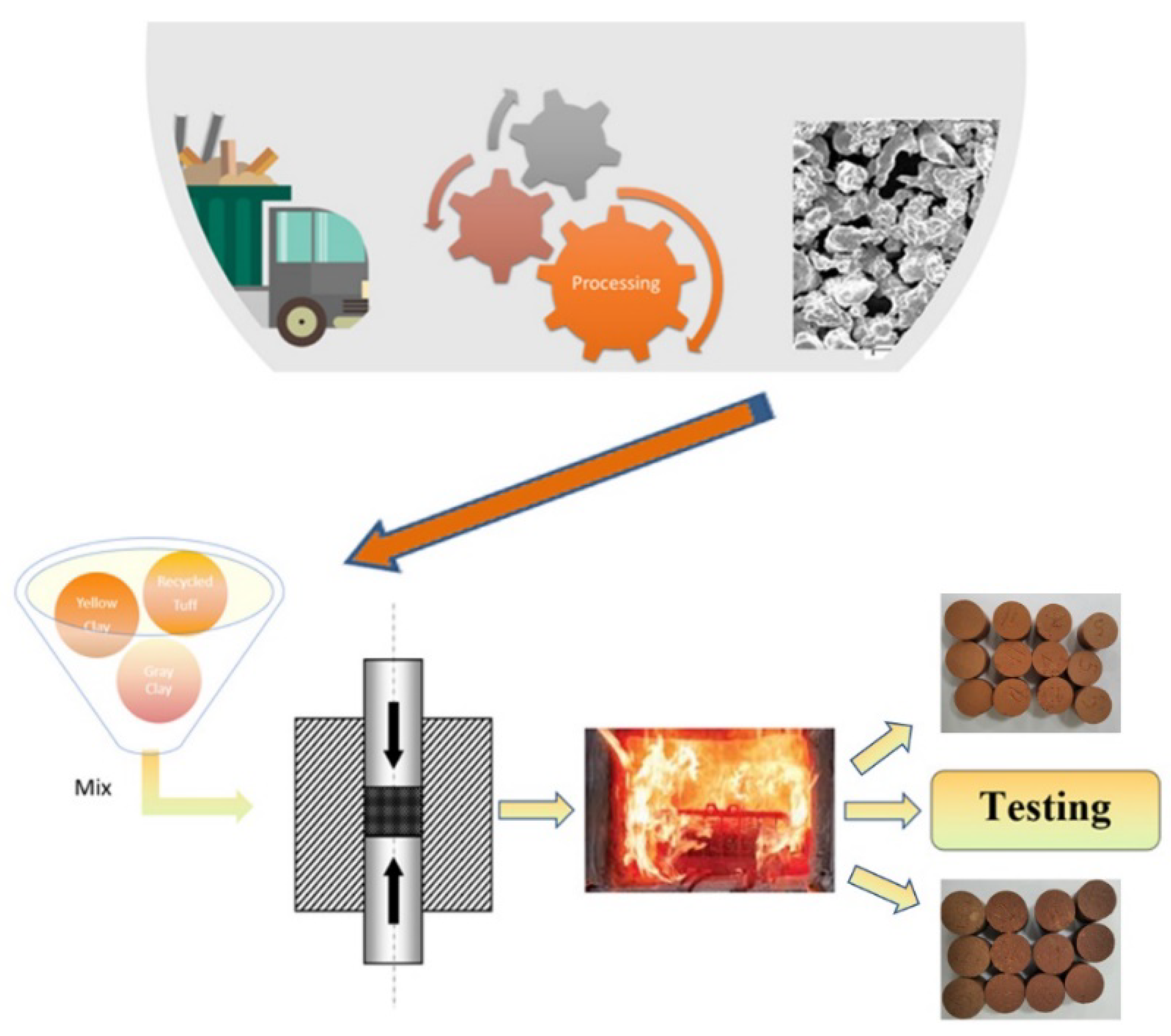
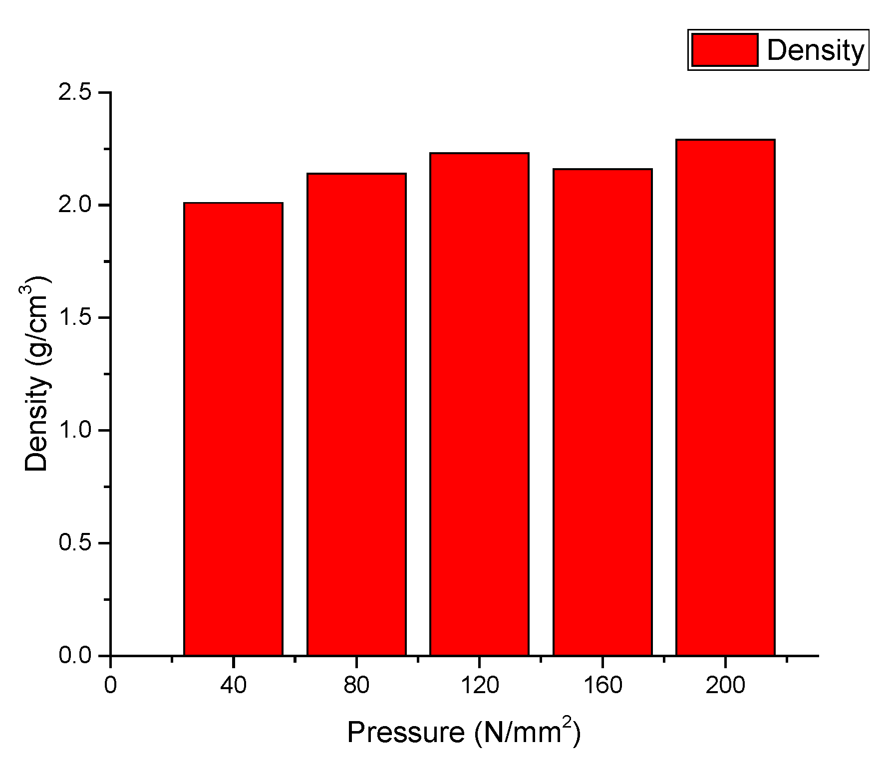
2.1. Specimens Preparation
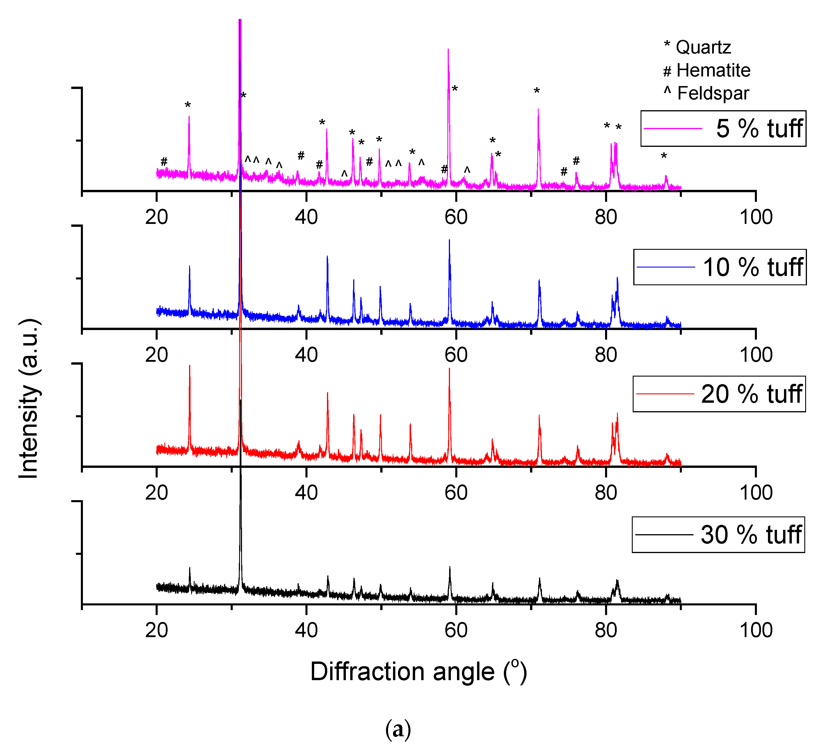
2.2. Analytical Methods
3. Results and Discussion
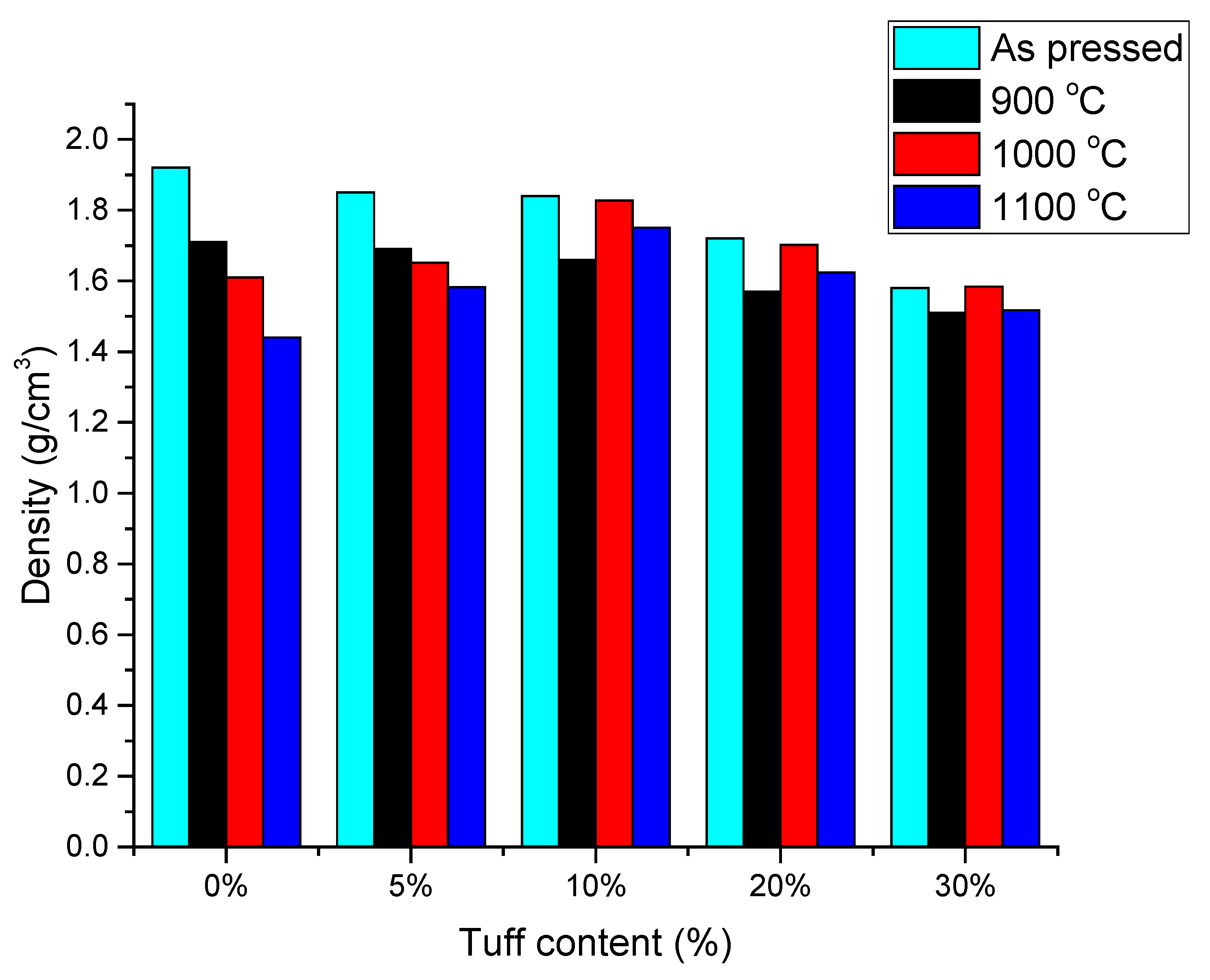
3.1. Density
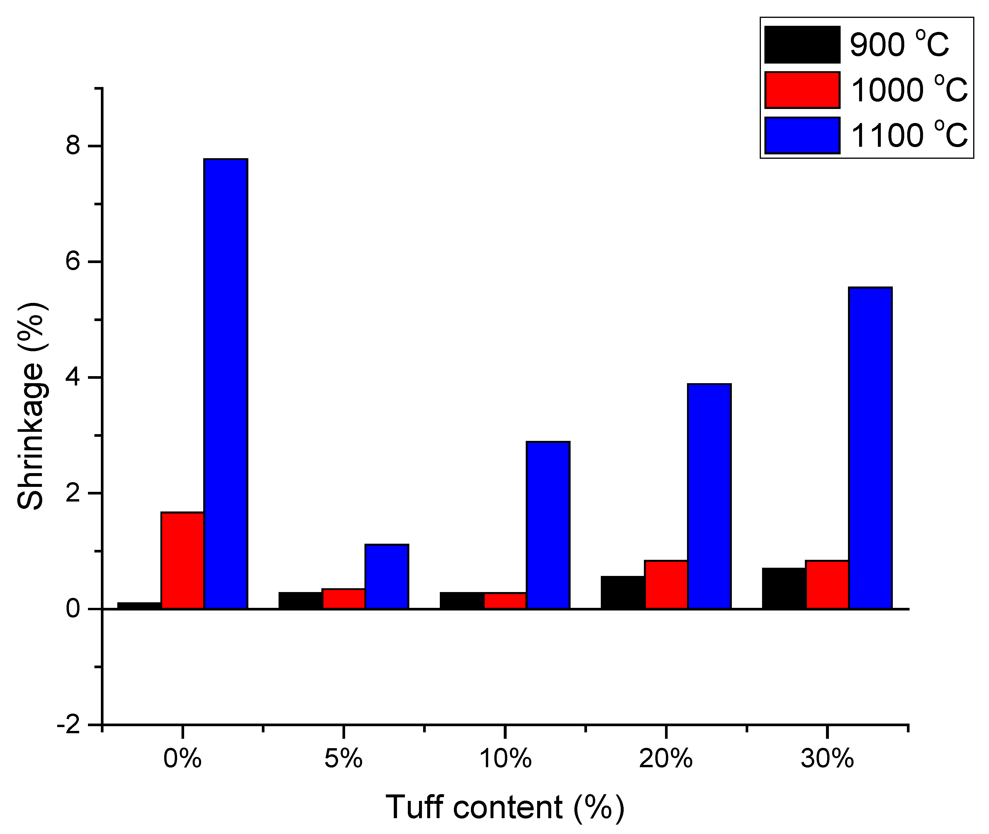
3.2. Shrinkage
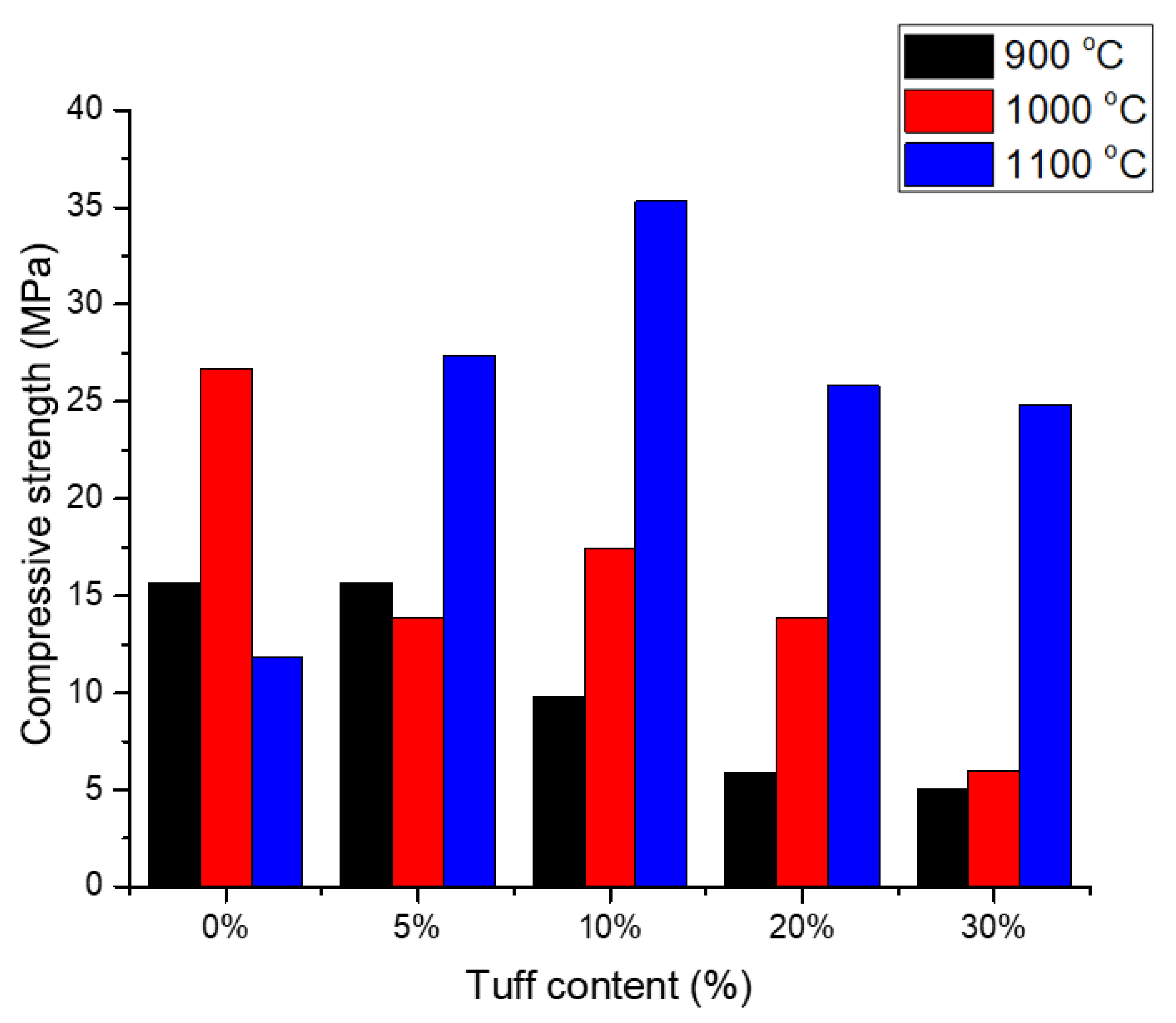
3.3. Compressive Strength
4. Conclusions, Contributions, and Further Work
- ✓
- The compressive strength of tuff–clay samples depended strongly on sintering temperature. When heated to 900 °C, the values of compressive strength were lower than 15.7 MPa for all samples (S2–S5). On the other hand, samples fired at 1100 °C presented higher compressive strengths, an increase of up to three-fold as compared with the reference bricks. This increase was due to the forming of stronger bonds between the particles. The increase in compression strength was also due to the formation of an important volume fraction of liquid that further accelerate the sintering process.
- ✓
- The added volcanic tuff further reduced the firing shrinkage. The formation of the liquid phase accelerated the sintering and, therefore, the firing shrinkage. By correctly choosing the sintering conditions we managed to reduce shrinkage by almost one magnitude lower, when comparing sample S2 to the reference sample S1 at 1100 °C. In the other cases the shrinkage reduction was also significant, though the difference was lower as the tuff content increased.
- ✓
- Increasing the firing temperature increased the embodied energy of the final product; however, by increasing the mechanical strength, one can add pore formers that improves thermal performance in energy-efficient buildings.
Author Contributions
Funding
Institutional Review Board Statement
Informed Consent Statement
Data Availability Statement
Conflicts of Interest
References
- Global Alliance for Buildings and Construction (GlobalABC); International Energy Agency (IEA); The United Nations Environment Programme. 2019 Global Status Report for Buildings and Construction: Towards a Zero-Emission, Efficient and Resilient Buildings and Construction Sector; United Nations Environment Programme: Nairobi, Kenya, 2019; Available online: https://globalabc.org/sites/default/files/2020-03/GSR2019.pdf (accessed on 2 August 2021).
- Ceramie-Unie. Ceramic Roadmap: Paving the Way to 2050. Available online: http://cerameunie.eu/topics/cerame-unie-sectors/cerame-unie/ceramic-industry-roadmap-paving-the-way-to-2050/ (accessed on 2 August 2021).
- Communication from the Commission to the European Parliament; The European Council; The Council; The European Economic and Social Committee; The Committee of The Regions. The European Green Deal COM/2019/640 Final. Available online: https://eur-lex.europa.eu/legal-content/EN/TXT/?uri=CELEX%3A52019DC0640 (accessed on 2 August 2021).
- European Commission. ‘Closing the loop—An EU Action Plan for the Circular Economy’. Communication from the Commission to the European Parliament, the Council, the European Economic and Social Committee and the Committee of the Regions. COM(2015) 614 Final. Available online: https://eur-lex.europa.eu/legal-content/EN/TXT/?uri=CELEX%3A52015DC0614 (accessed on 2 August 2021).
- COM. Towards a Circular Economy: A zero Waste Programme for Europe. 398 Final, 2014; pp. 1–14. Available online: https://eur-lex.europa.eu/resource.html?uri=cellar:aa88c66d-4553-11e4-a0cb-01aa75ed71a1.0022.03/DOC_1&format=PDF (accessed on 2 August 2021).
- Directive 2008/98/EC of the European Parliament and of the Council of 19 November 2008 on Waste and Repealing Certain Directives. Available online: https://eur-lex.europa.eu/legal-content/EN/TXT/?uri=celex%3A32008L0098 (accessed on 2 August 2021).
- Mulder, E.; de Jong, T.P.R.; Feenstra, L. Closed Cycle Construction: An integrated process for the separation and reuse of C&D waste. Waste Manag. 2007, 27, 1408–1415. [Google Scholar] [CrossRef]
- Szakács, A.; Pécskay, Z.; Silye, L.; Balogh, K.; Vlad, D.; Fülöp, A. On the age of the Dej Tuff, Transylvanian Basin (Romania). Geol. Carpathica 2012, 63, 139–148. [Google Scholar] [CrossRef] [Green Version]
- Cobîrzan, N.; Balog, A.-A.; Moşonyi, E. Investigation of the Natural Pozzolans for Usage in Cement Industry. Procedia Technol. 2015, 19, 506–511. [Google Scholar] [CrossRef] [Green Version]
- Barnat-Hunek, D.; Siddique, R.; Klimek, B.; Franus, M. The use of zeolite, lightweight aggregate and boiler slag in restoration renders. Constr. Build. Mater. 2017, 142, 162–174. [Google Scholar] [CrossRef]
- Terzić, A.; Pezo, L.; Mijatović, N.; Stojanović, J.; Kragović, M.; Miličić, L.; Andrić, L. The effect of alternations in mineral additives (zeolite, bentonite, fly ash) on physico-chemical behavior of Portland cement based binders. Constr. Build. Mater. 2018, 180, 199–210. [Google Scholar] [CrossRef]
- Tchadjié, L.N.; Ekolu, S.O.; Quainoo, H.; Tematio, P. Incorporation of activated bauxite to enhance engineering properties and microstructure of volcanic ash geopolymer mortar composites. J. Build. Eng. 2021, 41, 102384. [Google Scholar] [CrossRef]
- Liu, S.; Fang, P.; Wang, H.; Kong, Y.; Ouyang, L. Effect of tuff powder on the hydration properties of composite cementitious materials. Powder Technol. 2021, 380, 59–66. [Google Scholar] [CrossRef]
- Shahmansouri, A.A.; Bengar, H.A.; AzariJafari, H. Life cycle assessment of eco-friendly concrete mixtures incorporating natural zeolite in sulfate-aggressive environment. Constr. Build. Mater. 2021, 268, 121136. [Google Scholar] [CrossRef]
- Aškrabić, M.; Vyšvařil, M.; Zakić, D.; Savić, A.; Stevanović, B. Effects of natural zeolite addition on the properties of lime putty-based rendering mortars. Constr. Build. Mater. 2021, 270, 121363. [Google Scholar] [CrossRef]
- Gündüz, L.; Kalkan, Ş.O. Lightweight Cellular Hollow Concrete Blocks Containing Volcanic Tuff Powder, Expanded Clay and Diatomite for Non-Load Bearing Walls. Tek. Dergi 2020, 31, 10291–10313. [Google Scholar] [CrossRef] [Green Version]
- Tekin, I.; Kotan, T.; Osmanson, A.T.; Brostow, W.; Gencel, O.; Martinez-Barrera, G. Properties of lightweight concrete blocks with waste zeolitic tuff. Mater. Sci. 2020, 26, 463–470. [Google Scholar] [CrossRef]
- Woszuk, A.; Wróbel, M.; Franus, W. Application of Zeolite Tuffs as Mineral Filler in Warm Mix Asphalt. Materials 2020, 13, 19. [Google Scholar] [CrossRef] [Green Version]
- Piovesan, R.; Maritan, L.; Meneghin, G.; Previato, C.; Baklouti, S.; Sassi, R.; Mazzoli, C. Stones of the façade of the Sarno Baths, Pompeii: A mindful construction choice. J. Cult. Heritage 2019, 40, 255–264. [Google Scholar] [CrossRef]
- Vakalova, T.V.; Revva, I.B. Use of zeolite rocks for ceramic bricks based on brick clays and clay loams with high drying sensitivity. Constr. Build. Mater. 2020, 255, 119324. [Google Scholar] [CrossRef]
- Ahmadi, P.F.; Ardeshir, A.; Ramezanianpour, A.M.; Bayat, H. Characteristics of heat insulating clay bricks made from zeolite, waste steel slag and expanded perlite. Ceram. Int. 2018, 44, 7588–7598. [Google Scholar] [CrossRef]
- Gencel, O.; Sutcu, M.; Erdogmus, E.; Koc, V.; Cay, V.V.; Gok, M.S. Properties of bricks with waste ferrochromium slag and zeolite. J. Clean. Prod. 2013, 59, 111–119. [Google Scholar] [CrossRef]
- Nikolov, A.; Nugteren, H.; Rostovsky, I. Optimization of geopolymers based on natural zeolite clinoptilolite by calcination and use of aluminate activators. Constr. Build. Mater. 2020, 243, 118257. [Google Scholar] [CrossRef]
- Mârza, I.; Maszaros, N. Les tuffs volcaniques de Transilvanie, historique, valeur theoretique et practique dans le developpement de la gegologie transilvaine. In The Volcanic Tuffs from the Transylvanian Basin; Babeș-Bolyai University of Cluj-Napoca, Faculty of Biology-Geography-Geology, Geology-Mineralogy Department: Cluj-Napoca, Romania, 1991; pp. 11–22. [Google Scholar]
- Bedelean, I.; Stoici, S.D. Zeoliti; Tehnica: Bucuresti, Romania, 1984. [Google Scholar]
- Cobirzan, N.; Thalmaier, G.; Balog, A.-A.; Constantinescu, H.; Timiş, I.; Streza, M. Thermophysical properties of fired clay bricks with waste ceramics and paper pulp as pore-forming agent. J. Therm. Anal. Calorim. 2018, 134, 843–851. [Google Scholar] [CrossRef]
- Thalmaier, G.; Cobîrzan, N.; Balog, A.A.; Constantinescu, H.; Streza, M.; Nasui, M.; Neamtu, B.V. Influence of sawdust particle size on fired clay brick properties. Mater. Construcción 2020, 70, e215. [Google Scholar] [CrossRef]
- European Committee for Standardization. SR EN 772-13:2001. Methods of Test for Masonry Units: Determination of Net and Gross Dry Density of Masonry Units (Except for Natural Stone); In Romania; European Committee for Standardization: Brussels, Belgium.
- Domínguez, A.; Domínguez, M.; Ivanova, S.; Centeno, M.A.; Odriozola, J.A. Recycling of construction and demolition waste generated by building infrastructure for the production of glassy materials. Ceram. Int. 2016, 42, 15217–15223. [Google Scholar] [CrossRef]
- European Committee for Standardization. SR EN 771-1:2015. Specification for Masonry Units—Part 1: Clay Masonry Units; In Romania; European Committee for Standardization: Brussels, Belgium.
- Monitorul Oficial. CR6-2013–Design Code for Masonry Structures; National norm, in Romania; Monitorul Oficial: Iași, Romania, 2013; Volume 2. [Google Scholar]
- Monitorul Oficial. P100-1/2013—Seismic Design Code—Part I—Design Provisions for Buildings; National norm, in Romania; Monitorul Oficial: Iași, Romania, 2014. [Google Scholar]
- Kang, S.-J.L. Sintering: Densification, Grain Growth and Microstructure, 1st ed.; Elsevier: Burlington, VT, USA, 2005; pp. 37–41. [Google Scholar]
- Barbieri, L.; Andreola, F.; Lancellotti, I.; Taurino, R. Management of agricultural biomass wastes: Preliminary study on characterization and valorisation in clay matrix bricks. Waste Manag. 2013, 33, 2307–2315. [Google Scholar] [CrossRef] [PubMed]
- Cay, V.V.; Sutcu, M.; Gencel, O.; Korkut, T. Neutron Radiation Tests about FeCr Slag and Natural Zeolite Loaded Brick Samples. Sci. Technol. Nucl. Install. 2014, 2014, 971490. [Google Scholar] [CrossRef] [Green Version]
- Bonan, G. Chapter 5–Soil Temperature. In Climate Change and Terrestrial Ecosystem Modeling; Cambridge University Press: Cambridge, UK, 2019; pp. 64–79. [Google Scholar] [CrossRef]
- Barbero-Barrera, M.M.; Flores-Medina, N.; Moreno-Fernández, E. Thermal, physical and mechanical characterization of volcanic tuff masonries for the restoration of historic buildings. Mater. Construcción 2019, 69, e179. [Google Scholar] [CrossRef]


| Element | Yellow Clay | Grey Clay | Vulcanic Tuff |
|---|---|---|---|
| O | 65.80 | 55.63 | 65.12 |
| Na | 0.00 | 0.25 | 0.21 |
| Mg | 1.61 | 1.45 | 0.54 |
| Al | 7.72 | 11.20 | 4.99 |
| Si | 18.76 | 22.28 | 25.81 |
| K | 1.85 | 5.37 | 1.64 |
| Ca | 1.58 | 2.01 | 1 |
| Fe | 2.67 | 1.81 | 0.68 |
| Particle Size Distribution | D10 * | D50 * | D90 * | <5 µm | >63 µm |
|---|---|---|---|---|---|
| Grey clay | 2 µm | 11 µm | 35 µm | 25% | <1% |
| Yellow clay | 1.7 µm | 9 µm | 30 µm | 32% | <1% |
| Volcanic Tuff | 23 µm | 30 µm | 42 µm | 0% | 0% |
| Tuff Content [%] | Fired at 900 °C [g/cm3] | Fired at 1000 °C [g/cm3] | Fired at 1100 °C [g/cm3] |
|---|---|---|---|
| 0% | 1.71 | 1.61 | 1.44 |
| 5% | 1.69 | 1.65 | 1.58 |
| 10% | 1.66 | 1.83 | 1.75 |
| 20% | 1.57 | 1.70 | 1.62 |
| 30% | 1.51 | 1.58 | 1.52 |
| Tuff Content (%) | Fired at 900 °C (%) | Fired at 1000 °C (%) | Fired at 1100 °C (%) |
|---|---|---|---|
| 0% | 0.1 | 1.7 | 7.8 |
| 5% | 0.3 | 0.4 | 1.1 |
| 10% | 0.3 | 0.3 | 2.9 |
| 20% | 0.6 | 0.8 | 3.9 |
| 30% | 0.7 | 0.8 | 5.6 |
| Tuff Content (%) | Fired at 900 °C (MPa) | Fired at 1000 °C (MPa) | Fired at 1100 °C (MPa) |
|---|---|---|---|
| 0% | 15.7 MPa | 26.7 MPa | 11.8 MPa |
| 5% | 15.7MPa | 13.9 MPa | 27.4 MPa |
| 10% | 9.8 MPa | 17.4 MPa | 35.3 MPa |
| 20% | 5.9MPa | 13.9 MPa | 25.8 MPa |
| 30% | 5 MPa | 6 MPa | 25 MPa |
| Composition | Firing Temperature °C | Technical Characteristics | Reference | |
|---|---|---|---|---|
| Compressive Strength | Bulk Density | |||
| (MPa) | (g/cm3) | |||
| 70–100(wt.%) clay 0–30(wt.%) tuff | 900 | 15.7–5 | 1.71–1.51 | |
| 1000 | 26.7–6 | 1.61–1.58 | This paper | |
| 1100 | 35.3–11.8 | 1.44–1.52 | ||
| 70–100(wt.%) clay 0–30 (wt.%) natural zeolite | 1000 1050 | 32–24.2 33.8–23.1 | - | [20] |
| 70–100(wt.%) clay 0–30%(wt.%) natural zeolite | 900 | 34.9–14.3 | 1.68–1.48 | [22] |
| 70–100(wt.%) red clay 0–30(wt.%) zeolite rock | 900 | 34.9–14.3 | 1.68–1.48 | [35] |
Publisher’s Note: MDPI stays neutral with regard to jurisdictional claims in published maps and institutional affiliations. |
© 2021 by the authors. Licensee MDPI, Basel, Switzerland. This article is an open access article distributed under the terms and conditions of the Creative Commons Attribution (CC BY) license (https://creativecommons.org/licenses/by/4.0/).
Share and Cite
Cobîrzan, N.; Thalmaier, G.; Balog, A.-A.; Constantinescu, H.; Ceclan, A.; Nasui, M. Volcanic Tuff as Secondary Raw Material in the Production of Clay Bricks. Materials 2021, 14, 6872. https://doi.org/10.3390/ma14226872
Cobîrzan N, Thalmaier G, Balog A-A, Constantinescu H, Ceclan A, Nasui M. Volcanic Tuff as Secondary Raw Material in the Production of Clay Bricks. Materials. 2021; 14(22):6872. https://doi.org/10.3390/ma14226872
Chicago/Turabian StyleCobîrzan, Nicoleta, Gyorgy Thalmaier, Anca-Andreea Balog, Horia Constantinescu, Andrei Ceclan, and Mircea Nasui. 2021. "Volcanic Tuff as Secondary Raw Material in the Production of Clay Bricks" Materials 14, no. 22: 6872. https://doi.org/10.3390/ma14226872
APA StyleCobîrzan, N., Thalmaier, G., Balog, A.-A., Constantinescu, H., Ceclan, A., & Nasui, M. (2021). Volcanic Tuff as Secondary Raw Material in the Production of Clay Bricks. Materials, 14(22), 6872. https://doi.org/10.3390/ma14226872