
Challenges for Safe Electrolytes Applied in Lithium-Ion Cells—A Review


 , ,
, , 
 ,
,
Abstract
1. Introduction
- Organic electrolytes with nonflammable parts such as co-solvents or various additives for instant organic phosphorous compounds; they exhibit a high conductivity and good electrochemical performance;
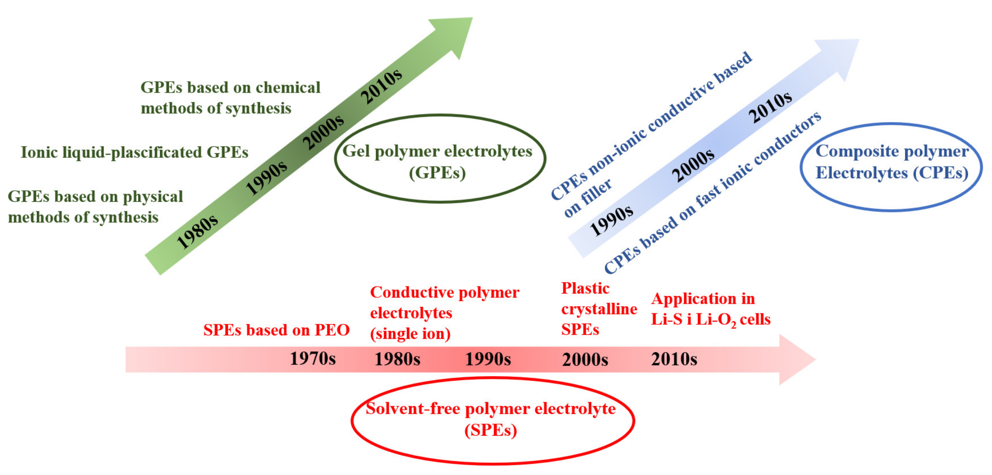
- Polymeric solid electrolytes consisting of polymer complexes with lithium salts for instant LiX/poly (ethylene oxide) (PEO); they exhibit a low conductivity at lower temperatures;
- Polymeric gel electrolytes with polymer complexes, which are swollen in organic solvents for instant LiX/alkylcarbonate/PEO with a nonflammable component; they exhibit high ionic conductivity;
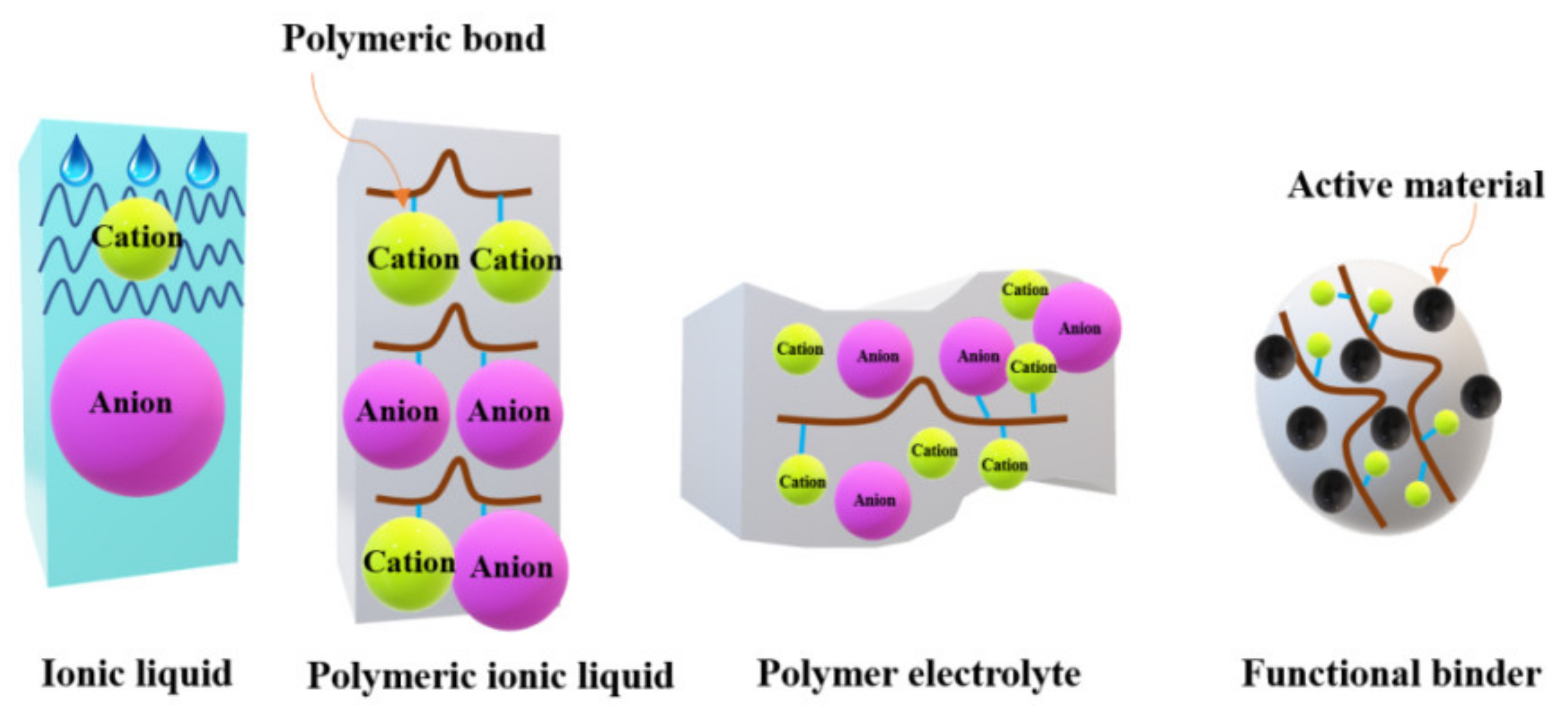
- Ionic liquids consisting of ionic liquids (ILs) dissolving lithium salt for instant LiX/IL, IL: 1-ethyl3methylimidazolium fluorosulfonyl amide (EMIFSA); they exhibit a high ionic conductivity and low-rate capability;
- Inorganic solid electrolytes constructed from lithium ion-containing oxides, sulfides, glass, and ceramics (superionic conductor Li10GeP2S12 crystal); they have a high ionic conductivity and a high mobility of lithium ions.
- Function-improving additives;
- Additives for safety improvement (e.g., anisole compounds, halogenobenzene compounds, alkylbenzene compounds for overcharge prevention) and phosphate and phosphazene compounds for non-flammability;
- Miscellaneous additives (e.g., corrosion inhibition);
- Additives for anodes (e.g., carboxylic acid anhydrides, oxalates);
- Additives for cathodes (e.g., sulfur-containing or aromatic compounds).
2. Results and Discussion
2.1. Safety Issues and Conventional Security of LIBs
2.2. Flammable Liquid Inorganic Electrolytes
2.3. Non-Flammable Electrolytes
2.3.1. Composite Polymer–Ceramic Electrolytes
2.3.2. Ionic Liquids
- Remaining liquids over a wide temperature range;
- Dissolving organic and inorganic compounds;
- Showing thermal and electrochemical stability;
- Being practically non-volatile;
- Having electrical conductivity;
- Dissolving catalysts (transition metal complexes);
- Keeping the activity of enzymes;
- Having catalytic action.

| Name | Abbreviation | Structure | References |
|---|---|---|---|
| Cation dialkyl imidazolium and anions | - |  | [89] |
 | |||
| 1-Allyl-3-methylimidazolium bis(trifluoromethanesulfonyl)imide | AMIMTFSI |  | [90] |
| N-n-butyl-N-methylpyrrolidinium hexafluorophosphate | ([Py14]PF6) |  | [91] |
| 1-Ethyl-1-methyl piperidinium bis(trifluoromethanesulfonyl)imide | EMP-TFSI |  | [92] |
| 1-butyl-3-methyl-imidazolium tetrafluoroborate | BMIMBF4 |  | [93] |
| N-methyl-N-propylpiperidinium bis(trifluoromethanesulfonyl)imide | PP13TFSI |  | [94] |
2.3.3. Polymeric Ionic Liquids
2.3.4. Polymer Electrolytes
- Void space theory (as a result of thermal changes, voids are formed, in which other ions may lodge);
- Percolation (leakage) theory (ion conductor as a system consisting of a series of conductive islands, around which there is a non-conductive area).
| Cell | Discharge Specific Capacity/mAh g−1 | References |
|---|---|---|
| Li/poli (bisAEA4-0.4 M) | 162 at C/20 | [96] |
| LiTFSI-MPPipTFSI)/LiFePO4 | 134 at C/2 | |
| Li/80% LiNfO-EMImNfO + 20% PVDF-HFP/LiCoO2 | 164 (C/10) | [97] |
| Li/P(VdF-HFP)-LiTFSI-PYR14 | 145.77 (at 60 °C) | [98] |
| TFSI (1:1:1)/LiFePO4 | 158.75 (at 80 °C) | |
| Li/PVdF/LiCoO2 | 149.1 | |
| Li/PVdF + SiO2/LiCoO2 | 152 | [99] |
| Li/PVdF + (SiO2-PAALi)/LiCoO2 | 156.5 |
2.3.5. Gel Polymer Electrolytes (GPEs)
2.3.6. Solid Polymer Electrolytes
2.4. Commonly Used Flame Tests
2.4.1. Self-Extinguishing Time (SET) Method
2.4.2. Flash Point (FP) Method
2.4.3. Thermogravimetric Analysis (TG) Flash Point (FP) Method
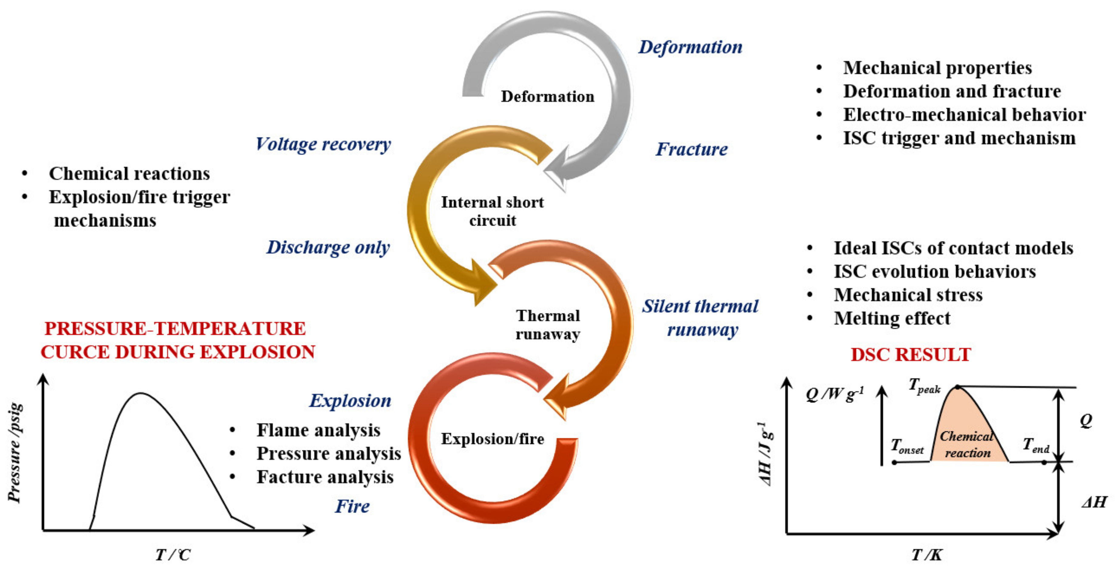
2.4.4. Differential Scanning Calorimeter (DSC)
2.4.5. Accelerating Rate Calorimetry (ARC)
2.5. Flammability of Different Electrochemical Systems
- Inherent safety methods (cathode modification, anode modification, safe electrolyte);
- Safety devices (safety vents and current interrupt devices, positive temperature coefficient devices, shutdown and ceramic-coated separators, battery management systems (BMS));
- Fire suppression and cooling (fire detection, fire extinguishing agents and methods).
3. Hydrogen—Future
3.1. Introduction
3.2. Road Transport and Hydrogen Fuel Cells
3.3. The Bus and Hydrogen Fuel Cells
3.4. Railway Transport and Hydrogen Fuel Cells
4. Conclusions
Author Contributions
Funding
Institutional Review Board Statement
Informed Consent Statement
Data Availability Statement
Acknowledgments
Conflicts of Interest
Abbreviations
| ΔH | Enthalpy |
| Q | Heat flow |
| T | Temperature |
| EC | Ethyl carbonate |
| DMC | Dimethyl carbonate |
| Al | Aluminum |
| LiClO4 | Lithium perchlorate |
| LiAsF6 | Lithium hexafluoroarsenate (V) |
| LiBF4 | Lithium tetrafluoroborate |
| LiN(SO2F)2 (LISFI) | Lithium bis(fluorosulfuryl)imide |
| POF3 | Phosphoryl fluoride |
| PF5 | Phosphorus pentafluoride |
| LLZTO | Li6.4La3Zr1.4Ta0.6O12 |
| EO | Ethylene oxide |
| LLTO | Li0.33La0.557TiO3 |
| PAN | Poly(acrylonitrile) |
| BisAEA4 | Ethoxylated bisphenol A diacrylate |
| LiFePO4 | Lithium iron phosphate |
| MPPipTFSI | N-methyl-N-propylpiperidinium bis(trifluoromethanesulfonyl)imide |
| LiNfO | Lithium nonafluoro-1-butanesulfonate |
| EMImNfO | 1-ethyl-3-methyl imidazolium nonfluoro-1-butanesulfonate |
| PYR14-TFSI | 1-butyl-1-methyl pyrrolidinium bis(trifluoromethylsulfonyl)imide |
| SiO2-PAALi | Silicon dioxide–ion complex |
| LiCoO2 | Lithium cobalt oxide |
| CO | Carbon monoxide |
| CH4 | Methane |
| C2H4 | Ethylene |
| C2H6 | Ethane |
| C3H6 | Propene |
| HDV | High duty vehicle |
| DEC | Diethyl carbonate |
| CO2 | Carbon dioxide |
| Et2O | Ethyl ether |
| SN | Succinonitrile |
| LATP | NASICON-type lithium aluminum titanium phosphate |
| LiTFSI | Lithium bis(trifluoromethanesulfonyl)imide |
| PVDF | Polyvinylidene fluoride |
| HFP | Hexafluoropropylene |
| EMITFSI | Lithium bis(trifluoromethanesulfonyl)imide |
| LAGP | NASICON-type Li1.5Al0.5Ge1.5(PO4)3 |
| PEGDA | Polyethylene glycol diacrylate |
| PFPN | Ethoxy(pentafluoro)cyclotriphosphazene |
| FPPN | Pentafluoro(phenoxy)cyclotriphosphazene |
| LiCoO2 | Lithium cobalt oxide |
| C3H8 | Propane |
| TMP | Trimethyl phosphate |
| TEP | Triethyl phosphate |
| TBP | Tributyl phosphate |
| TFP | Tris(2,2,2-trifluoroethyl) phosphate |
| BMP | Bis(2,2,2-trifluoroethyl) methylphosphonate |
| TMPi | Trimethyl phosphite |
| TTFPi | Tris(2,2,2-trifluoroethyl) phosphite |
| DMMP | Dimethyl methylphosphonate |
| DEEP | Diethyl ethylphosphonate |
| TFMP | Bis(2,2,2-trifluoroethyl) methylphosphonate |
| TFEP | Bis(2,2,2-trifluoroethyl) ethylphosphonate |
| HMOCPN | Hexamethoxycyclotriphosphazene |
| NMP | N-methyl-2-pyrrolidone |
| CSR | Corporate social responsibility |
References
- Li, Q.; Chen, J.; Fan, L.; Kong, F. Progress in electrolytes for rechargeable Li-based batteries and beyond. Green Energy Environ. 2016, 1, 18–42. [Google Scholar] [CrossRef]
- Balducci, A. Ionic Liquids in Lithium-Ion Batteries. In Ionic Liquids II; Springer: Berlin/Heidelberg, Germany, 2017; pp. 1–27. [Google Scholar]
- Iwakura, C.; Fukumoto, Y.; Inoue, H.; Ohashi, S.; Kobayashi, S.; Tada, H.; Abe, M. Electrochemical characterization of various metal foils as a current collector of positive electrode for rechargeable lithium batteries. J. Power Sources 1997, 68, 301–303. [Google Scholar] [CrossRef]
- Henderson, W.A. Nonaqueous Electrolytes: Advances in Lithium Salts. In Electrolytes for Lithium and Lithium-Ion Batteries; Springer: Berlin/Heidelberg, Germany, 2014; pp. 1–92. [Google Scholar]
- Wang, Q.; Jiang, L.; Yu, Y.; Sun, J. Progress of enhancing the safety of lithium ion battery from the electrolyte aspect. Nano Energy 2018, 55, 93–114. [Google Scholar] [CrossRef]
- Belov, D.G.; Shieh, D.T. A study of tetrabromobisphenol A (TBBA) as a flame retardant additive for Li-ion battery electrolytes. J. Power Sources 2014, 247, 865. [Google Scholar] [CrossRef]
- Liu, K.; Liu, Y.; Lin, D.; Pei, A.; Cui, Y. Materials for lithium-ion battery safety. Sci. Adv. 2018, 4, eaas9820. [Google Scholar] [CrossRef]
- Ue, M.; Sasaki, Y.; Tanaka, Y.; Morita, M. Nonaqueous Electrolytes with Advances in Solvents. In Electrolytes for Lithium and Lithium-Ion Batteries. Modern Aspects of Electrochemistry; Springer: Berlin/Heidelberg, Germany, 2014; p. 58. [Google Scholar]
- Goodenough, J.B.; Kim, Y. Challenges for Rechargeable Li Batteries (Review). Chem. Mater. 2010, 22, 589. [Google Scholar] [CrossRef]
- Barbosa, J.C.; Correia, D.M.; Gonçalves, R.V.; de Zea Bermudez, C.M. Costa Enhanced ionic conductivity in poly(vinylidene fluoride) electrospun separator membranes blended with different ionic liquids for lithium ion batteriesJ. Colloid and Interface. Science 2021, 582, 376–386. [Google Scholar]
- Eshetu, G.G.; Mecerreyes, D.; Forsyth, M.; Zhang, H.; Armand, M. Polymeric ionic liquids for lithium-based rechargeable batteries. Mol. Syst. Des. Eng. 2019, 4, 294–309. [Google Scholar] [CrossRef]
- Zou, K.; Deng, W.; Cai, P.; Deng, X.; Wang, B.; Liu, C.; Li, J.; Hou, H.; Zou, G.; Ji, X. Prelithiation/Presodiation Techniques for Advanced Electrochemical Energy Storage Systems: Concepts, Applications, and Perspectives. Adv. Funct. Mater. 2021, 31, 2005581. [Google Scholar] [CrossRef]
- Ray, A.; Saruhan, B. Review Application of Ionic Liquids for Batteries and Supercapacitors. Materials 2021, 14, 2942. [Google Scholar] [CrossRef]
- Ouyang, D.; Chen, M.; Huang, Q.; Weng, J.; Wang, Z.; Wang, J. A Review on the Thermal Hazards of the Lithium-Ion Battery and the Corresponding Countermeasures. Appl. Sci. 2019, 9, 2483. [Google Scholar] [CrossRef]
- Yeon, D.; Lee, Y.; Ryou, M.H.; Lee, Y.M. New flame-retardant composite separators based on metal hydroxides for lithium-ion batteries. Electrochim. Acta 2015, 157, 282–289. [Google Scholar] [CrossRef]
- Lee, T.; Kim, W.K.; Lee, Y.; Ryou, M.H.; Lee, Y.M. Effect of Al2O3 coatings prepared by RF sputtering on polyethylene sep-arators for high-power lithium ion batteries. Macromol. Res. 2014, 22, 1190–1195. [Google Scholar] [CrossRef]
- Lee, J.-Y.; Shin, S.-H.; Moon, S.-H. Flame retardant coated polyolefin separators for the safety of lithium ion batteries. Korean J. Chem. Eng. 2015, 33, 285–289. [Google Scholar] [CrossRef]
- Zhang, J.; Yue, L.; Kong, Q.; Liu, Z.; Zhou, X.; Zhang, C.; Xu, Q.; Zhang, B.; Ding, G.; Qin, B.; et al. Sustainable, heat-resistant and flame-retardant cellulose-based composite separator for high-performance lithium ion battery. Sci. Rep. 2014, 4, 3935. [Google Scholar] [CrossRef]
- Lewandowski, A.; Kurc, B.; Świderska-Mocek, A.; Kusa, N. Graphite|LiFePO4 lithium-ion battery working at the heat engine coolant temperature. J. Power Sources 2014, 266, 132–137. [Google Scholar] [CrossRef]
- Liu, B.; Jia, Y.; Yuan, C.; Wang, L.; Gao, X.; Yin, S.; Xu, J. Safety issues and mechanisms of lithium-ion battery cell upon mechanical abusive loading: A review. Energy Storage Mater. 2019, 24, 85–112. [Google Scholar] [CrossRef]
- Balakrishnan, P.G.; Ramesh, R.; Prem Kumar, T. Safety mechanisms in lithium-ion batteries—Review. J. Power Sources 2006, 155, 401. [Google Scholar] [CrossRef]
- Wen, J.; Yu, Y.; Chen, C. A Review on Lithium-Ion Batteries Safety Issues: Existing Problems and Possible Solutions. Mater. Express 2012, 2, 197–212. [Google Scholar] [CrossRef]
- Van Schalkwijk, W.A.; Scrosati, B. Advances in Lithium-Ion Batteries; Kluwer Academic Publishers: New York, NY, USA, 2002. [Google Scholar]
- Aurbach, D.; Zaban, A.; Gofer, Y.; Ein-Eli, Y.; Weissman, I.; Chusid, O.; Abramson, O.; Markovsky, B. Recent studies of the lith-ium-liquid electrolyte interface Electrochemical, morphological and spectral studies of a few important systems. J. Power Sources 1995, 54, 76–80. [Google Scholar] [CrossRef]
- Zheng, X.; Li, G.; Guo, Y.; You, H.; Li, S.; Xio, R.; Zheng, J. Yttrium trihydride enhanced lithium storage in carbon materials. Carbon 2020, 164, 317–323. [Google Scholar] [CrossRef]
- Aurbach, D.; Markovsky, B.; Levi, M.; Levi, E.; Schechter, A.; Moshkovich, M.; Cohen, Y. New insights into the interactions between electrode materials and electrolyte solutions for advanced nonaqueous batteries. J. Power Sources 1999, 81–82, 95–111. [Google Scholar] [CrossRef]
- Mori, S.; Asahina, H.; Suzuki, H.; Yonei, A.; Yokoto, K. Chemical properties of various organic electrolytes for lithium re-chargeable batteries: 1. Characterization of passivating layer formed on graphite in alkyl carbonate solutions. J. Power Sources 1997, 68, 59–64. [Google Scholar] [CrossRef]
- Peled, E. The Electrochemical Behavior of Alkali and Alkaline Earth Metals in Nonaqueous Battery Systems—The Solid Elec-trolyte Interphase Model. J. Electrochem. Soc. 1979, 126, 2047–2052. [Google Scholar] [CrossRef]
- Ein-Eli, Y.; Markovsky, B.; Aurbach, D.; Carmeli, Y.; Amin, H.Y.; Luski, S. The dependence of the performance of Li-C inter-ca-lation anodes for Li-ion secondary batteries on the electrolyte solution composition. Electrochim. Acta 1994, 39, 2559–2569. [Google Scholar] [CrossRef]
- Aurbach, D.; Zaban, A.; Ein-Eli, Y.; Weissman, I.; Chusid, O.; Markovsky, B.; Levi, M.; Levi, E.; Schechter, A.; Granot, E. Recent studies on the correlation between surface chemistry, morphology, three-dimensional structures and performance of Li and Li-C intercalation anodes in several important electrolyte systems. J. Power Sources 1997, 68, 91–98. [Google Scholar] [CrossRef]
- Dollé, M.; Grugeon, S.; Beaudoin, B.; Dupont, L.; Tarascon, J.-M. In situ TEM study of the interface carbon/electrolyte. J. Power Sources 2001, 97–98, 104–106. [Google Scholar] [CrossRef]
- Winter, M.; Wrodnigg, G.H.; Besenhard, J.O.; Biberacher, W.; Novák, P. Dilatometric Investigations of Graphite Electrodes in Nonaqueous Lithium Battery Electrolytes. J. Electrochem. Soc. 2000, 147, 2427–2431. [Google Scholar] [CrossRef]
- Inaba, M.; Kawatate, Y.; Funabiki, A.; Jeong, S.-K.; Abe, T.; Ogumi, Z. STM study on graphite/electrolyte interface in lithium-ion batteries: Solid electrolyte interface formation in trifluoropropylene carbonate solution. Electrochim. Acta 1999, 45, 99–105. [Google Scholar] [CrossRef]
- Jeong, S.-K.; Inaba, M.; Iriyama, Y.; Abe, T.; Ogumi, Z. Surface film formation on a graphite negative electrode in lithium-ion batteries: AFM study on the effects of co-solvents in ethylene carbonate-based solutions. Electrochim. Acta 2002, 47, 1975–1982. [Google Scholar] [CrossRef]
- Edstroem, K.; Herstedt, M.; Abraham, D.P. A new look at the solid electrolyte interphase on graphite anodes in Li-ion batteries. J. Power Sources 2006, 153, 380–384. [Google Scholar] [CrossRef]
- Aurbach, D. Review of selected electrode–solution interactions which determine the performance of Li and Li ion batteries. J. Power Sources 2000, 89, 206–218. [Google Scholar] [CrossRef]
- Peled, E.; Golodnitsky, D.; Ardel, G. Advanced Model for Solid Electrolyte Interphase Electrodes in Liquid and Polymer Elec-trolytes. J. Electrochem. Soc. 1997, 144, L208–L212. [Google Scholar] [CrossRef]
- Zaban, A.; Aurbach, D. Impedance spectroscopy of lithium and nickel electrodes in propylene carbonate solutions of different lithium salts A comparative study. J. Power Sources 1995, 54, 289–295. [Google Scholar] [CrossRef]
- Andersson, A.; Henningson, A.; Siegbahn, H.; Jansson, U.; Edström, K. Electrochemically lithiated graphite characterised by photoelectron spectroscopy. J. Power Sources 2003, 119–121, 522–527. [Google Scholar] [CrossRef]
- Zheng, T.; Gozdz, A.S.; Amatucci, G.G. Reactivity of the Solid Electrolyte Interface on Carbon Electrodes at Elevated Tem-per-atures. J. Electrochem. Soc. 1999, 146, 4014. [Google Scholar] [CrossRef]
- Du Pasquier, A.; Disma, F.; Bowmer, T.; Gozdz, A.S.; Amatucci, G.; Tarascon, J. Differential Scanning Calorimetry Study of the Reactivity of Carbon Anodes in Plastic Li-Ion Batteries. J. Electrochem. Soc. 1998, 145, 472–477. [Google Scholar] [CrossRef]
- Bryngelsson, H.; Stjerndahl, M.; Gustafsson, T.; Edström, K. How dynamic is the SEI? J. Power Sources 2007, 174, 970–975. [Google Scholar] [CrossRef]
- Besenhard, J.; Winter, M.; Yang, J.; Biberacher, W. Filming mechanism of lithium-carbon anodes in organic and inorganic electrolytes. J. Power Sources 1995, 54, 228–231. [Google Scholar] [CrossRef]
- Liebenow, C.; Wagner, M.W.; Lühder, K.; Lobitz, P.; Besenhard, J.O. Electrochemical behaviour of coated lithium carbon elec-trodes. J. Power Sources 1995, 54, 369–374. [Google Scholar] [CrossRef]
- Yan, P.; Zhu, Y.; Pan, X.; Ji, H. A novel flame-retardant electrolyte additive for safer lithium-ion batteries. Int. J. Energy Res. 2020, 30, 1–9. [Google Scholar] [CrossRef]
- Aurbach, D.; Levi, M.D.; Levi, A.E.; Schechter, A. Failure and Stabilization Mechanisms of Graphite Electrodes. J. Phys. Chem. B 1997, 101, 2195–2206. [Google Scholar] [CrossRef]
- Ein-Eli, Y. A New Perspective on the Formation and Structure of the Solid Electrolyte Interface at the Graphite Anode of Li-Ion Cells. Electrochem. Solid-State Lett. 1999, 2, 212–214. [Google Scholar] [CrossRef]
- Aurbach, D.; Teller, H.; Koltypin, M.; Levi, E. On the behavior of different types of graphite anodes. J. Power Sources 2003, 119–121, 2–7. [Google Scholar] [CrossRef]
- Aurbach, D.; Zinigrad, E.; Cohen, Y.; Teller, H. A short review of failure mechanisms of lithium metal and lithiated graphite anodes in liquid electrolyte solutions. Solid State Ionics 2002, 148, 405–415. [Google Scholar] [CrossRef]
- Sun, X.-G.; Dai, S. Electrochemical investigations of ionic liquids with vinylene carbonate for applications in rechargeable lithium ion batteries. Electrochim. Acta 2010, 55, 4618–4626. [Google Scholar] [CrossRef]
- Kang, S.H.; Abraham, D.P.; Xiao, A.; Lucht, B.L. Investigating the solid electrolyte interphase using binder-free graphite elec-trodes. J. Power Sources 2008, 175, 526–529. [Google Scholar] [CrossRef]
- Sato, T.; Aruo, T.M.; Marukane, S.; Takagi, K. Ionic liquids containing carbonate solvent as lectrolyte for lithium ion cells. J. Power Sources 2004, 138, 253–261. [Google Scholar] [CrossRef]
- Holzapfel, M.; Jost, C.; Prodi-Schwab, A.; Krumeich, F.; Würsig, A.; Buqa, H.; Novák, P. Stabilisation of lithiated graphite in an electrolyte based on ionic liquids: An electrochemical and scanning electron microscopy study. Carbon 2005, 43, 1488–1498. [Google Scholar] [CrossRef]
- Holzapfel, M.; Jost, C.; Novák, P. Stable cycling of graphite in an ionic liquid based electrolyte. Chem. Commun. 2004, 18, 2098–2099. [Google Scholar] [CrossRef]
- Zheng, H.H.; Jiang, K.; Abe, T.; Ogumi, Z. Electrochemical intercalation of lithium into a natural graphite anode in quaternary ammonium-based ionic liquid electrolytes. Carbon 2006, 44, 203–210. [Google Scholar] [CrossRef]
- Fu, Y.; Chen, C.; Qiu, C.; Ma, X. Vinyl ethylene carbonate as an additive to ionic liquid electrolyte for lithium ion batteries. J. Appl. Electrochem. 2009, 39, 2597–2603. [Google Scholar] [CrossRef]
- Aurbach, D.; Gamolsky, K.; Markovsky, B.; Gofer, Y.; Schmidt, M.; Heider, U. On the use of vinylene carbonate (VC) as an additive to lectrolyte solutions for Li-ION batteries. Electrochim. Acta 2002, 47, 1423. [Google Scholar] [CrossRef]
- Buqa, H.; Würsig, A.; Vetter, J.; Spahr, M.E.; Krumeich, F.; Novák, P. SEI fim formatiom on highlycrystalline graphitic materials in lithium ion batteries. J. Power Sources 2006, 153, 385–390. [Google Scholar] [CrossRef]
- Zhang, X.; Kostecki, R.; Richardson, T.J.; Pugh, J.K.; Ross, P.N., Jr. Electrochemical and infarde studies of the reduction of organic carbonates. J. Electrochem. Soc. 2001, 148, A1341. [Google Scholar] [CrossRef]
- Herstedt, M.; Andersson, A.; Rensmo, H.; Siegbahn, H.; Edström, K. Characterisation of the SEI formed on natural graphite in PC-based electrolytes. Electrochim. Acta 2004, 49, 4939–4947. [Google Scholar] [CrossRef]
- Itagaki, M.; Yotsuda, S.; Kobari, N.; Watanabe, K.; Kinoshita, S.; Ue, M. Elctrochemical impedance of electrolyte/electrodenterfaces of lithium-ion rechargeable batteries: Effects of additives to the electrolyte on negative electrode. Electrochim. Acta 2006, 51, 1629. [Google Scholar] [CrossRef]
- Vetter, J.; Novák, P.; Wagner, M.; Veit, C.; Möller, K.-C.; Besenhard, J.; Winter, M.; Wohlfahrt-Mehrens, M.; Vogler, C.; Hammouche, A. Ageing mechanisms in lithium-ion batteries. J. Power Sources 2005, 147, 269–281. [Google Scholar] [CrossRef]
- Yuan, X.; Liu, H.; Zhang, J. Lithium- Ion Batteries, Advanced Materials and Technologies; CRC Press: Boca Raton, FL, USA, 2011; pp. 198–206. [Google Scholar]
- Ding, B.; Yu, H. Electrospun Nanofibers for Energy and Environmental Applications; Springer: Berlin/Heidelberg, Germany, 2014; pp. 105–110. [Google Scholar]
- Lee, H.; Cho, J.J.; Kim, J.; Kim, H.J. Comparison of voltammetric responses over cathodic region in LiPF6 and LiBETI with or without HF. Electrochem. Soc. 2005, 152, A1193–A1198. [Google Scholar] [CrossRef]
- Rosenberg, E.; Kanakaki, C.; Amon, A.; Gocheva, I.; Trifonova, A. Understanding the degradation processes of the electrolyte of lithium ion batteries by chromatographic analysis. Bulg. Chem. Commun. 2017, 49, 242–253. [Google Scholar]
- Amon, A. Degredation of Organic Compound. Master’s Thesis, University of Vienna, Vienna, Austria, 2015. [Google Scholar]
- Hartning, C.; Schmidt, M.; Korthauer, R. Handbuch Lithium-Ionen-Batterien; Springer: Berlin/Heidelberg, Germany, 2013; pp. 61–77. [Google Scholar]
- Wilken, S.; Treskow, M.; Scheers, J.; Johansson, P.; Jacobsson, P. Initial stages of thermal decomposition of LiPF6-based lithium ion battery electrolytes by detailed Raman and NMR spectroscopy. RSC Adv. 2013, 3, 16359–16364. [Google Scholar] [CrossRef]
- Ravdel, B.; Abraham, K.; Gitzendanner, R.; DiCarlo, I.; Lucht, B.; Campion, C. Thermal stability of lithium-ion battery elec-trolytes. J. Power Sources 2003, 119, 805–810. [Google Scholar] [CrossRef]
- Waldmann, T.; Hogg, B.-I.; Wohlfahrt-Mehrens, M. Li plating as unwanted side reaction in commercial Li-ion cells—A review. J. Power Sources 2018, 384, 107–124. [Google Scholar] [CrossRef]
- Wu, X.; Song, K.; Zhang, X.; Hu, N.; Li, L.; Li, W.; Zhang, L.; Zhang, H. Safety Issues in Lithium Ion Batteries: Materials and Cell Design. Front. Energy Res. 2019, 7, 65. [Google Scholar] [CrossRef]
- Yu, X.; Manthiram, A. A review of composite polymer-ceramic electrolytes for lithium batteries. Energy Storage Mater. 2020, 34, 282–300. [Google Scholar] [CrossRef]
- Yu, X.; Li, J.; Manthiram, A. Rational Design of a Laminated Dual-Polymer/Polymer–Ceramic Composite Electrolyte for High-Voltage All-Solid-State Lithium Batteries. ACS Mater. Lett. 2020, 2, 317–324. [Google Scholar] [CrossRef]
- Xia, Y.; Wang, X.L.; Xia, X.H.; Xu, R.C.; Zhang, S.Z.; Wu, J.B.; Liang, Y.F.; Gu, C.D.; Tu, J.P. A newly designed composite gel polymer electrolyte based on poly(vinylidene fluoride-hexafluoropropylene) (PVDF-HFP) for enhanced solid-state lithi-um-sulfur batteries. Chem.-Eur. J. 2017, 23, 15203–15209. [Google Scholar] [CrossRef]
- Wang, W.; Yi, E.; Fici, A.J.; Laine, R.M.; Kieffer, J. Lithium Ion Conducting Poly(ethylene oxide)-Based Solid Electrolytes Containing Active or Passive Ceramic Nanoparticles. J. Phys. Chem. C 2017, 121, 2563–2573. [Google Scholar] [CrossRef]
- Guo, Q.P.; Han, Y.; Wang, H.; Xiong, S.Z.; Li, Y.J.; Liu, S.K.; Xie, K. New class of LAGP-based solid polymer composite electrolyte for efficient and safe solid-state lithium batteries. ACS Appl. Mater. Inter. 2017, 9, 41837–41844. [Google Scholar] [CrossRef]
- Zhang, Z.; Zhao, Y.; Chen, S.; Xie, D.; Yao, X.; Cui, P.; Xu, X. An advanced construction strategy of all-solid-state lithium batteries with excellent interfacial compatibility and ultralong cycle life. J. Mater. Chem. A 2017, 5, 16984–16993. [Google Scholar] [CrossRef]
- Duan, H.; Fan, M.; Chen, W.P.; Li, J.Y.; Wang, P.F.; Wang, W.P.; Shi, J.L.; Yin, Y.X.; Wan, L.J.; Guo, Y.G. Extended elec-trochemical window of solid electrolytes via heterogeneous multilayered structure for high-voltage lithium metal batteries. Adv. Mater. 2019, 31, 1807789. [Google Scholar] [CrossRef]
- Zhu, P.; Yan, C.; Zhu, J.; Zang, J.; Li, Y.; Jia, H.; Dong, X.; Du, Z.; Zhang, C.; Wu, N.; et al. Flexible electrolyte-cathode bilayer framework with stabilized interface for room-temperature all-solid-state lithium-sulfur batteries. Energy Storage Mater. 2018, 17, 220–225. [Google Scholar] [CrossRef]
- Cheng, S.H.S.; He, K.Q.; Liu, Y.; Zha, J.W.; Kamruzzaman, M.; Ma, R.L.W.; Dang, Z.M.; Li, R.K.Y.; Chung, C.Y. Elec-trochemical performance of all-solid-state lithium batteries using inorganic lithium garnets particulate reinforced PEO/LiClO4 electrolyte. Electrochim. Acta 2017, 253, 430–438. [Google Scholar] [CrossRef]
- Li, Y.; Zhang, W.; Dou, Q.; Wong, K.W.; Ng, K.M. Li7La3Zr2O12 ceramic nanofiber-incorporated composite polymer electrolytes for lithium metal batteries. J. Mater. Chem. A 2019, 7, 3391–3398. [Google Scholar] [CrossRef]
- Liang, J.-Y.; Zeng, X.-X.; Zhang, X.-D.; Zuo, T.-T.; Yan, M.; Yin, Y.-X.; Shi, J.-L.; Wu, X.-W.; Guo, Y.-G.; Wan, L.-J. Engineering Janus Interfaces of Ceramic Electrolyte via Distinct Functional Polymers for Stable High-Voltage Li-Metal Batteries. J. Am. Chem. Soc. 2019, 141, 9165–9169. [Google Scholar] [CrossRef]
- Francis, C.F.J.; Kyratzis, I.L.; Best, A.S. Lithium-Ion Battery Separators for Ionic-Liquid Electrolytes: A Review. Adv. Mater. 2020, 32, 1904205. [Google Scholar] [CrossRef] [PubMed]
- Qi, H.; Ren, Y.; Guo, S.; Wang, Y.; Li, S.; Hu, Y.; Yan, F. High-Voltage Resistant Ionic Liquids for Lithium-Ion Batteries. ACS Appl. Mater. Interfaces 2019, 12, 591–600. [Google Scholar] [CrossRef] [PubMed]
- Menne, S.; Pires, J.; Anouti, M.; Balducci, A. Protic ionic liquids as electrolytes for lithium-ion batteries. Electrochem. Commun. 2013, 31, 39–41. [Google Scholar] [CrossRef]
- Yamagata, M.; Tanaka, K.; Tsuruda, Y.; Sone, Y.; Fukuda, S.; Nakasuka, S.; Kono, M.; Ishikawa, M. The First Lithium-ion Battery with Ionic Liquid Electrolyte Demonstrated in Extreme Environment of Space. Electrochemistry 2015, 83, 918–924. [Google Scholar] [CrossRef]
- Chatterjee, K.; Pathak, A.D.; Lakma, A.; Sharma, C.S.; Sahu, K.K.; Singh, A.K. Synthesis, characterization and application of a non-flammable dicationic ionic liquid in lithium-ion battery as electrolyte additive. Sci. Rep. 2020, 10, 9606. [Google Scholar] [CrossRef]
- Zygadło-Monikowska, E.; Florjanczyk, Z.; Kubisa, P.; Biedron, T.; Sadurski, W.; Puczyłows, A.; Langwald, N.; Ostrowska, J. Lithium electrolytes based on modified imidazolim ionic liquids. Int. J. Hydrogen Energy 2014, 39, 2943. [Google Scholar] [CrossRef]
- Wang, M.; Shan, Z.; Tian, J.; Yang, K.; Liu, X.; Liu, H.; Zhu, K. Mixtures of unsaturated imidazolium based ionic liquid and organic carbonate as electrolyte for Li-ion batteries. Electrochim. Acta 2013, 95, 301–307. [Google Scholar] [CrossRef]
- Tsurumaki, A.; Navarra, M.A.; Panero, S.; Scrosati, B.; Ohno, H. N-n-Butyl-N-methylpyrrolidinium hexafluorophos-phate-added electrolyte solutions and membranes for lithium-secondary batteries. J. Power Sources 2013, 233, 104. [Google Scholar] [CrossRef]
- Kim, K.; Cho, Y.-H.; Shin, H.-C. 1-Ethyl-1-methyl piperidinium bis(trifluoromethanesulfonyl)imide as a co-solvent in Li-ion batteries. J. Power Sources 2013, 225, 113–118. [Google Scholar] [CrossRef]
- Wang, H.; Li, S.; Huang, K.; Yin, X.; Liu, Y.; Peng, S. BMIMBF4 Ionic Liquid Mixtures Electrolyte for Li-ion Batteries. Int. J. Electrochem. Sci. 2012, 7, 1688. [Google Scholar]
- An, Y.; Zuo, P.; Cheng, X.; Liao, L.; Yin, G. The effects of LiBOB additive for stable SEI formation of PP13TFSI-organic mixed electrolyte in lithium ion batteries. Electrochim. Acta 2011, 56, 4841–4848. [Google Scholar] [CrossRef]
- Arya, A.; Sharma, A.L. Polymer electrolytes for lithium ion batteries: A critical study. Ionics 2017, 23, 497–540. [Google Scholar] [CrossRef]
- Stepniak, I.; Andrzejewska, E.; Dembna, A.; Galinski, M. Characterization and application of N-methyl-N-propylpiperidinium bis(trifluoromethanesulfonyl)imide ionic liquid–based gel polymer electrolyte prepared in situ by photopolymerization method in lithium ion batteries. Electrochim. Acta 2014, 121, 27–33. [Google Scholar] [CrossRef]
- Karuppasamy, K.; Reddy, P.A.; Srinivas, G.; Sharma, R.; Tewari, A.; Kumar, G.H.; Gupta, D. An efficient way to achieve high ionic conductivity and electrochemical stability of safer nonaflate anion-based ionic liquid gel polymer electrolytes (ILGPEs) for rechargeable lithium ion batteries. J. Solid State Electrochem. 2016, 21, 1145–1155. [Google Scholar] [CrossRef]
- Li, L.; Wang, J.; Yang, P.; Guo, S.; Wang, H.; Yang, X.; Ma, X.; Yang, S.; Wu, B. Preparation and characterization of gel polymer electrolytes containing N-butyl-N-methylpyrrolidinium bis(trifluoromethanesulfonyl) imide ionic liquid for lithium ion batter-ies. Electrochim. Acta 2013, 88, 147–156. [Google Scholar] [CrossRef]
- Li, W.; Xing, Y.; Wu, Y.; Wang, J.; Chen, L.; Yang, G.; Tang, B. Study the effect of ion-complex on the properties of composite gel polymer electrolyte based on Electrospun PVdF nanofibrous membrane. Electrochim. Acta 2015, 151, 289–296. [Google Scholar] [CrossRef]
- Zhou, D.; Shanmukaraj, D.; Tkacheva, A.; Armand, M.; Wang, G. Polymer Electrolytes for Lithium-Based Batteries: Advances and Prospects. Chem 2019, 5, 2326–2352. [Google Scholar] [CrossRef]
- Gupta, H.; Singh, R.K. Ionic Liquid-Based Gel Polymer Electrolytes for Application in Rechargeable Lithium Batteries. IntechOpen 2020, 7, 20–25. [Google Scholar] [CrossRef]
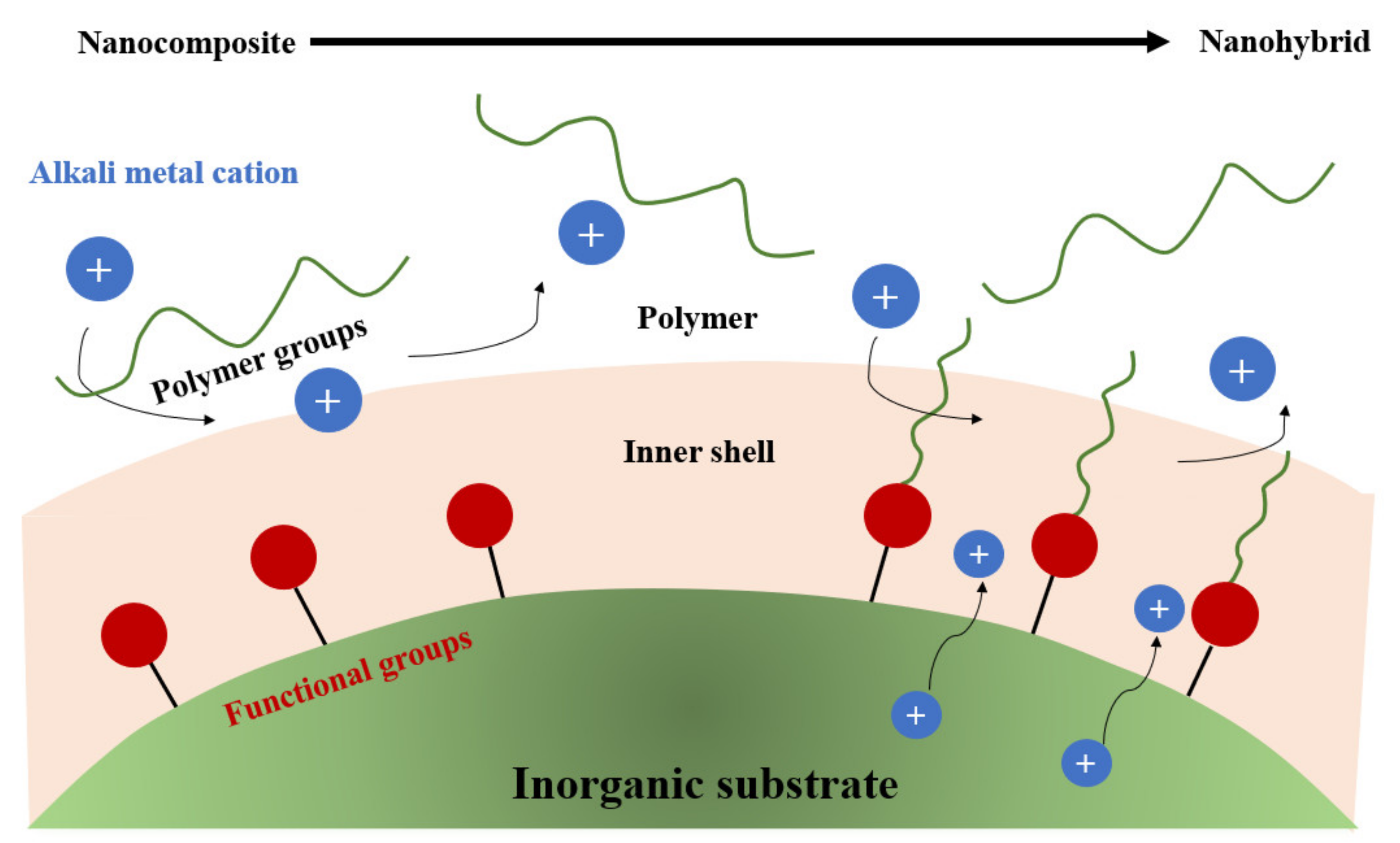
- Boaretto, N.; Meabe, L.; Martinez-Ibañez, M.; Armand, M.; Zhang, H. Review—Polymer Electrolytes for Rechargeable Batteries: From Nanocomposite to Nanohybrid. J. Electrochem. Soc. 2020, 167, 70524. [Google Scholar] [CrossRef]
- Liang, S.; Yan, W.; Wu, X.; Zhang, Y.; Zhu, Y.; Wang, H.; Wu, Y. Gel polymer electrolytes for lithium ion batteries: Fabrication, characterization and performance. Solid State Ion. 2018, 318, 2–18. [Google Scholar] [CrossRef]
- Li, X.; Qian, K.; He, Y.-B.; Liu, C.; An, D.; Li, Y.; Zhou, D.; Lin, Z.; Li, B.; Yang, Q.-H.; et al. A dual-functional gel-polymer electrolyte for lithium ion batteries with superior rate and safety performances. J. Mater. Chem. A 2017, 5, 18888–18895. [Google Scholar] [CrossRef]
- Zhao, X.; Tao, C.-A.; Li, Y.; Chen, X.; Wang, J.; Gong, H. Preparation of gel polymer electrolyte with high lithium ion transference number using GO as filler and application in lithium battery. Ionics 2020, 26, 4299–4309. [Google Scholar] [CrossRef]
- Li, L.; Wang, M.; Wang, J.; Ye, F.; Wang, S.; Xu, Y.; Liu, J.; Xu, G.; Zhang, Y.; Zhang, Y.; et al. Asymmetric gel polymer electrolyte with high lithium ion conductivity for dendrite-free lithium metal batteries. J. Mater. Chem. A 2020, 8, 8033–8040. [Google Scholar] [CrossRef]
- Logan, M.W.; Langevin, S.; Tan, B.; Freeman, A.W.; Hoffman, C.; Trigg, D.B.; Gerasopoulos, K. UV-cured eutectic gel polymer electrolytes for safe and robust Li-ion batteries. J. Mater. Chem. A 2020, 8, 8485–8495. [Google Scholar] [CrossRef]
- Tang, S.; Guo, W.; Fu, Y. Advances in Composite Polymer Electrolytes for Lithium Batteries and Beyond. Adv. Energy Mater. 2020, 11, 2000802. [Google Scholar] [CrossRef]
- Marangon, V.; Tominaga, Y.; Hassoun, J. An alternative composite polymer electrolyte for high performances lithium battery. J. Power Sources 2019, 449, 227508. [Google Scholar] [CrossRef]
- Yue, L.; Ma, J.; Zhang, J.; Zhao, J.; Dong, S.; Liu, Z.; Cui, G.; Chen, L. All solid-state polymer electrolytes for high-performance lithium ion batteries. Energy Storage Mater. 2016, 5, 139–164. [Google Scholar] [CrossRef]
- Wang, B.; Lou, H.; Xu, H.; Zhao, J.; Wang, Q.; Shi, Q.; Deng, Y. High voltage, solvent-free solid polymer electrolyte based on a star-comb PDLLA–PEG copolymer for lithium ion batteries. RSC Adv. 2018, 8, 6373–6380. [Google Scholar] [CrossRef]
- He, R.; Echeverri, M.; Ward, D.; Zhu, Y.; Kyu, T. Highly conductive solvent-free polymer electrolyte membrane for lithium-ion batteries: Effect of prepolymer molecular weight. J. Membr. Sci. 2016, 498, 208–217. [Google Scholar] [CrossRef]
- Zhang, H.P.; Zhang, P.; Li, Z.H.; Sun, M.; Wu, Y.P.; Wu, H.Q. A novel sandwiched membrane as polymer electrolyte for lithium ion battery. Electrochem. Commun. 2007, 9, 1700–1703. [Google Scholar] [CrossRef]
- Rajendran, S.; Sivakumar, M.; Subadevi, R.; Nirmala, M. Characterization of PVA–PVdF based solid polymer blend electro-lytes. Phys. B Condens. Matter. 2004, 348, 73–78. [Google Scholar] [CrossRef]
- Tamilselvi, P.; Hema, M. Structural, thermal, vibrational, and electrochemical behavior of lithium ion conducting solid polymer electrolyte based on poly (vinyl alcohol)/poly (vinylidene fluoride) blend. Polymer. Sci. Ser. A 2016, 58, 1–9. [Google Scholar] [CrossRef]
- Rajendran, S.; Prabhu, M.R.; Rani, M.U. Characterization of PVC/PEMA based polymer blend electrolytes. Int. J. Electrochem. Sci. 2008, 3, 282–290. [Google Scholar]
- Hess, S.; Wohlfahrt-Mehrens, M.; Wachtler, M. Flammability of Li-Ion Battery Electrolytes: Flash Point and Self-Extinguishing Time Measurements. J. Electrochem. Soc. 2015, 162, A3084–A3097. [Google Scholar] [CrossRef]
- Patil, G.S. Estimation of flash point. Fire Mater. 1988, 12, 127–131. [Google Scholar] [CrossRef]
- Abdelkhalik, A.; Elsayed, H.; Hassan, M.; Nour, M.; Shehata, A.B.; Helmy, M. Using thermal analysis techniques for identi-fying the flash point temperatures of some lubricant and base oils. Egypt. J. Pet. 2018, 27, 131–136. [Google Scholar] [CrossRef]
- Gnanaraj, J.S.; Zinigrad, E.; Asraf, L.; Gottlieb, H.E.; Sprecher, M.; Aurbach, D.; Schmidt, M. The use of accelerating rate calorimetry (ARC) for the study of the thermal reactions of Li-ion battery electrolyte solutions. J. Power Sources 2003, 119, 794–798. [Google Scholar] [CrossRef]
- Jang, J.; Dahn, J.R. ARC studies of the thermal stability of three different cathode materials: LiCoO2; Li[Ni0.1Co0.8Mn0.1]O2; and LiFePO4, in LiPF6 and LiBoB EC/DEC electrolytes. Electrochem. Commun. 2004, 6, 39–43. [Google Scholar] [CrossRef]
- Mendoza-Hernandez, O.S.; Taniguchi, S.; Ishikawa, H.; Tanaka, K.; Fukuda, S.; Sone, Y.; Umeda, M. Accelerating rate calo-rimetry tests of lithium-ion cells before and after storage degradation at high temperature. E3S Web Conf. 2017, 16, 7001. [Google Scholar] [CrossRef]
- Hirschler, M.M. Flame retardants and heat release: Review of traditional studies on products and on groups of polymers. Fire Mater. 2014, 39, 207–231. [Google Scholar] [CrossRef]
- Li, H.; Peng, W.; Yang, X.; Chen, H.; Sun, J.; Wang, Q. Full-Scale Experimental Study on the Combustion Behavior of Lithium Ion Battery Pack Used for Electric Vehicle. Fire Technol. 2020, 56, 2545–2564. [Google Scholar] [CrossRef]
- Wang, Q.; Mao, B.; Stoliarov, S.I.; Sun, J. A review of lithium ion battery failure mechanisms and fire prevention strategies. Prog. Energy Combust. Sci. 2019, 73, 95–131. [Google Scholar] [CrossRef]
- Dagger, T.; Rad, B.R.; Schappacher, F.M.; Winter, M. Comparative Performance Evaluation of Flame Retardant Additives for Lithium Ion Batteries—I. Safety, Chemical and Electrochemical Stabilities. Energy Technol. 2018, 6, 2011–2022. [Google Scholar] [CrossRef]
- Pham, H.Q.; Nam, K.M.; Hwang, E.H.; Kwon, Y.G.; Jung, H.M.; Song, S.W. Performance Enhancement of 4.8 V Li1.2Mn0.525Ni0.175Co0.1O2 Battery Cathode Using Fluorinated Linear Carbonate as a High-Voltage Additive. J. Electrochem. Soc. 2014, 161, 2002–2011. [Google Scholar] [CrossRef]
- Chawla, N.; Bharti, N.; Singh, S. Recent Advances in Non-Flammable Electrolytes for Safer Lithium-Ion Batteries. Batteries 2019, 5, 19. [Google Scholar] [CrossRef]
- Haregewoin, A.M.; Wotango, A.S.; Hwang, B.J. Electrolyte additives for lithium ion battery electrodes: Progress and per-spectives. Energy Environ. Sci. 2016, 9, 1955–1988. [Google Scholar] [CrossRef]
- Fathabadi, H. A novel design including cooling media for Lithium-ion batteries packused in hybrid and electric vehicles. J. Power Sources 2014, 245, 495. [Google Scholar] [CrossRef]
- Jarrett, A.; Kim, I.Y. Influence of operating conditions on the optimum design of electric vehicle battery cooling plates. J. Power Sources 2014, 245, 644. [Google Scholar] [CrossRef]
- Högström, K.C.; Lundgren, H.; Wilken, S.; Zavalis, T.G.; Behm, M.; Edstroem, K.; Jacobsson, P.; Johansson, P.; Lindbergh, G. Impact of the flame retardant additive triphenyl phosphate (TPP) on the performance of graphite/LiFePO4 cells in high power applications. J. Power Sources 2014, 256, 430–439. [Google Scholar] [CrossRef]
- Watanabe, M.; Thomas, M.L.; Zhang, S.; Ueno, K.; Yasuda, M.; Dokko, K. Application of Ionic Liquids to Energy Storage and Conversion Materials and Devices. Chem. Rev. 2017, 10, 7190–7239. [Google Scholar] [CrossRef]
- Zheng, J.; Li, X.; Yu, Y.; Feng, X.; Zhao, Y. Novel high phosphorus content phosphaphenanthrene-based efficient flame re-tardant additives for lithium-ion battery. J. Therm. Anal. Calorim. 2014, 117, 319–324. [Google Scholar] [CrossRef]
- Xun, J.; Liu, R.; Jiao, K. Numerical and analytical modeling of lithium ion battery thermal behaviors with different cooling designs. J. Power Sources 2013, 233, 47–61. [Google Scholar] [CrossRef]
- Li, X.; He, F.; Ma, L. Thermal management of cylindrical batteries investigated using wind tunnel testing and computational fluid dynamics simulation. J. Power Sources 2013, 238, 395–402. [Google Scholar] [CrossRef]
- Xiao, M.; Choe, S.-Y. Theoretical and experimental analysis of heat generations of a pouch type LiMn2O4/carbon high power Li-polymer battery. J. Power Sources 2013, 241, 46–55. [Google Scholar] [CrossRef]
- Karimi, G.; Dehghan, A.R. Thermal Management Analysis of a Lithium-Ion Battery Pack using Flow Network Approach. Int. J. Mech. Eng. Mechatron. 2012, 1, 88–94. [Google Scholar] [CrossRef][Green Version]
- Arbizzani, C.; Gabrielli, G.; Mastragostino, M. Thermal stability and flammability of electrolytes for lithium-ion batteries. J. Power Sources 2011, 196, 4801–4805. [Google Scholar] [CrossRef]
- Cho, Y.-H.; Kim, K.; Ahn, S.; Liu, H.K. Allyl-substituted triazines as additives for enhancing the thermal stability of Li-ion batteries. J. Power Sources 2011, 196, 1483–1487. [Google Scholar] [CrossRef]
- Forgez, C.; Do, D.V.; Friedrich, G.; Morcrette, M.; Delacourt, C. Thermal modeling of a cylindrical LiFePO4/graphite lithium-ion battery. J. Power Sources 2010, 195, 2961–2968. [Google Scholar] [CrossRef]
- Fei, S.-T.; Allcock, H.R. Methoxyethoxyethoxyphosphazenes as ionic conductive fire retardant additives for lithium battery systems. J. Power Sources 2010, 195, 2082–2088. [Google Scholar] [CrossRef]
- Zygadło-Monikowska, E.; Florjańczyk, Z.; Kubisa, P.; Biedroń, T.; Tomaszewska, A.; Ostrowska, J.; Langwald, N. Mixture of LiBF4 and lithium difluoro(oxalato)borate for application as a new electrolyte for lithium-ion batteries. J. Power Sources 2010, 195, 6202–6206. [Google Scholar] [CrossRef]
- Viswanathan, V.V.; Choi, D.; Wang, D.; Xu, W.; Towne, S.; Williford, R.E.; Zhang, J.-G.; Liu, J.; Yang, Z. Effect of entropy change of lithium intercalation in cathodes and anodes on Li-ion battery thermal management. J. Power Sources 2010, 195, 3720–3729. [Google Scholar] [CrossRef]
- Xiang, H.; Wang, H.; Chen, C.; Ge, X.; Guo, S.; Sun, J.; Hu, W. Thermal stability of LiPF6-based electrolyte and effect of contact with various delithiated cathodes of Li-ion batteries. J. Power Sources 2009, 191, 575–581. [Google Scholar] [CrossRef]
- Onda, K.; Ohshima, T.; Nakayama, M.; Fukuda, K.; Araki, T. Thermal behavior of small lithium-ion battery during rapid charge and discharge cycles. J. Power Sources 2006, 158, 535. [Google Scholar] [CrossRef]
- Doughty, D.H.; Roth, E.P.; Crafts, C.C.; Nagasubramanian, G.; Henriksen, G.; Amine, K. Effects of additives on thermal stability of Li ion cells. J. Power Sources 2005, 146, 116–120. [Google Scholar] [CrossRef]
- Dixon, B.G.; Morris, R.S.; Dallek, S. Non-flammable polyphosphonate electrolytes. J. Power Sources 2004, 138, 274–276. [Google Scholar] [CrossRef]
- Ding, M.S.; Xu, K.; Jow, T.R. Effects of Tris(2,2,2-trifluoroethyl) Phosphate as a Flame-Retarding Cosolvent on Physicochemical Properties of Electrolytes of LiPF6 in EC-PC-EMC of 3:3:4 Weight Ratios. J. Electrochem. Soc. 2002, 149, 1489. [Google Scholar] [CrossRef]
- Akashi, H.; Sekai, K.; Tanaka, K.-I. A novel fire-retardant polyacrylonitrile-based gel electrolyte for lithium batteries. Electrochim. Acta 1998, 43, 1193–1197. [Google Scholar] [CrossRef]
- Ramar, V.; Pszolla, C.; Rapp, M.; Borck, M.; Zinck, L. Non-flammable Inorganic Liquid Electrolyte Lithium-Ion Batteries. J. Electrochem. Soc. 2020, 167, 70521. [Google Scholar] [CrossRef]
- Zeng, L.; Jia, L.; Liu, X.; Zhang, C. A Novel Silicon/Phosphorus Co-Flame Retardant Polymer Electrolyte for High-Safety All-Solid-State Lithium Ion Batteries. Polymers 2020, 12, 2937. [Google Scholar] [CrossRef]
- Cao, X.; Xu, Y.; Zhang, L.; Engelhard, M.H.; Zhong, L.; Ren, X.; Jia, H.; Liu, B.; Niu, C.; Matthews, B.E.; et al. Nonflammable Electrolytes for Lithium Ion Batteries Enabled by Ultraconformal Passivation Interphases. ACS Energy Lett. 2019, 4, 2529–2534. [Google Scholar] [CrossRef]
- Kurc, B. Sulfolane with LiPF6, LiNTf2 and LiBOB—As a non-Flammable Electrolyte Working in a lithium-ion batteries with a LiNiO2 Cathode. Int. J. Electrochem. Sci. 2018, 5938–5955. [Google Scholar] [CrossRef]
- Gao, T.; Wang, B.; Wang, L.; Liu, G.; Wang, F.; Luo, H.; Wang, D. LiAlCl4·3SO2 as a high conductive, non-flammable and inorganic non-aqueous liquid electrolyte for lithium ion batteries. Electrochim. Acta 2018, 286, 77–85. [Google Scholar] [CrossRef]
- Shi, P.; Fang, S.; Huang, J.; Luo, D.; Yang, L.; Hirano, S.-I. A novel mixture of lithium bis(oxalato)borate, gamma-butyrolactone and non-flammable hydrofluoroether as a safe electrolyte for advanced lithium ion batteries. J. Mater. Chem. A 2017, 5, 19982–19990. [Google Scholar] [CrossRef]
- Im, J.; Lee, J.; Ryou, M.-H.; Lee, Y.M.; Cho, K.Y. Fluorinated Carbonate-Based Electrolyte for High-Voltage Li(Ni0.5Mn0.3Co0.2)O2/Graphite Lithium-Ion Battery. J. Electrochem. Soc. 2017, 164, A6381–A6385. [Google Scholar] [CrossRef]
- Wang, J.; Mai, Y.; Luo, H.; Yan, X.; Zhang, L. Fluorosilane compounds with oligo(ethylene oxide) substituent as safe electrolyte solvents for high-voltage lithium-ion batteries. J. Power Sources 2016, 334, 58–64. [Google Scholar] [CrossRef]
- Zeng, Z.; Wu, B.; Xiao, L.; Jiang, X.; Chen, Y.; Ai, X.; Yang, H.; Cao, Y. Electrolyte additives for lithium ion battery electrodes: Progress and perspectives. J. Power Sources 2015, 279, 6–12. [Google Scholar] [CrossRef]
- Altarawneh, M.; Dlugogorski, B.Z. Mechanism of Thermal Decomposition of Tetrabromobisphenol A (TBBA). J. Phys. Chem. A. 2014, 118, 9338–9346. [Google Scholar] [CrossRef] [PubMed]
- Benmayza, A.; Lu, W.; Ramani, V.; Prakash, J. Electrochemical and Thermal Studies of LiNi0.8Co0.15Al0.015O2 under Fluorinated Electrolytes. Electrochim. Acta 2014, 123, 7–13. [Google Scholar] [CrossRef]
- Li, H.; Pang, J.; Yin, Y.; Zhuang, W.; Wang, H.; Zhai, C.; Lu, S. Application of a nonflammable electrolyte containing Pp13TFSI ionic liquid for lithium-ion batteries using the high capacity cathode material Li[0.2Mn0.54Ni0.13Co0.13]O2. RSC Adv. 2013, 3, 13907–13914. [Google Scholar] [CrossRef]
- Lee, D.J.; Im, D.; Ryu, Y.-G.; Lee, S.; Yoon, J.; Lee, J.; Choi, W.; Jung, I.-S.; Lee, S.; Doo, S.-G. Phosphorus derivatives as electrolyte additives for lithium-ion battery: The removal of O 2 generated from lithium-rich layered oxide cathode. J. Power Sources 2013, 243, 831–835. [Google Scholar] [CrossRef]
- Cao, X.; Yixiao, L.; Li, X.; Zheng, J.; Gao, J.; Gao, Y.; Wu, X.; Zhao, Y.; Yang, Y. Novel Phosphamide Additive to Improve Thermal Stability of Solid Electrolyte Interphase on Graphite Anode in Lithium-Ion Batteries. Appl. Mater. Interfaces 2013, 5, 11494. [Google Scholar] [CrossRef]
- Sánchez-Ramírez, N.; Assresahegn, B.D.; Bélanger, D.; Torresi, R.M. Comparison among Viscosity, Density, Conductivity, and Electrochemical Windows of N-n-Butyl-N-methylpyrrolidinium and Triethyl-n-pentylphosphonium Bis(fluorosulfonyl imide) Ionic Liquids and Their Analogues Containing Bis(trifluoromethylsulfonyl) Imide Anion. J. Chem. Eng. Data 2017, 62, 3437–3444. [Google Scholar]
- Lombardo, L.; Brutti, S.; Assunta, M.; Panero, N.S.; Reale, P. Mixtures of ionic liquid—Alkylcarbonates as electrolytes for safe lithium-ion batteries. J. Power Sources 2013, 227, 8. [Google Scholar] [CrossRef]
- Karuppasamy, K.; Theerthagiri, J.; Vikraman, D.; Yim, C.-J.; Hussain, S.; Sharma, R.; Maiyalagan, T.; Qin, J.; Kim, H.-S. Ionic Liquid-Based Electrolytes for Energy Storage Devices: A Brief Review on Their Limits and Applications. Polymers 2020, 12, 918. [Google Scholar] [CrossRef]
- Jin, Z.; Gao, H.; Kong, C.; Zhan, H.; Li, Z. A Novel Phosphate-Based Flame Retardant and Film-Forming Electrolyte Additive for Lithium Ion Batteries. ECS Electrochem. Lett. 2013, 2, A66–A68. [Google Scholar] [CrossRef]
- Wang, Z.; Cai, Y.; Wang, Z.; Chen, S.; Lu, X.; Zhang, S. Vinyl-functionalized imidazolium ionic liquids as new electrolyte additives for high-voltage Li-ion batteries. J. Solid State Electrochem. 2013, 17, 2839–2848. [Google Scholar] [CrossRef]
- Venkatraman, V.; Evjen, S.; Chellappan Lethesh, K. The Ionic Liquid Property Explorer: An Extensive Library of Task-Specific Solvents. Data 2019, 4, 88. [Google Scholar] [CrossRef]
- Feng, J.; Lu, L. A novel bifunctional additive for safer lithium ion batteries. J. Power Sources 2013, 243, 29. [Google Scholar] [CrossRef]
- Wu, B.; Pei, F.; Wu, Y.; Mao, R.; Ai, X.; Yang, H.; Cao, Y. An electrochemically compatible and flame-retardant electrolyte additive for safe lithium ion batteries. J. Power Sources 2013, 227, 106–110. [Google Scholar] [CrossRef]
- Lin, F.; Wang, J.; Jia, H.; Monroe, C.W.; Yang, J.; NuLi, Y. Nonflammable electrolyte for rechargeable lithium battery with sulfur based composite cathode materials. J. Power Sources 2013, 223, 18–22. [Google Scholar] [CrossRef]
- Feng, J.; Ma, P.; Yang, H.; Lu, L. Understanding the interactions of phosphonate-based flame-retarding additives with graphitic anode for lithium ion batteries. Electrochim. Acta 2013, 114, 688–692. [Google Scholar] [CrossRef]
- Nishikawa, D.; Nakajima, T.; Ohzawa, Y.; Koh, M.; Yamauchi, A.; Kagawa, M.; Aoyama, H. Thermal and oxidation stability of organo-fluorine compound-mixed electrolyte solutions for lithium ion batteries. J. Power Sources 2013, 243, 573–580. [Google Scholar] [CrossRef]
- Albalawi, A.H.; El-Sayed, W.S.; Aljuhani, A.; Almutairi, S.M.; Rezki, N.; Aouad, M.R.; Messali, M. Microwave-Assisted Synthesis of Some Potential Bioactive Imidazolium-Based Room-Temperature Ionic Liquids. Molecules 2018, 23, 1727. [Google Scholar] [CrossRef]
- Hu, J.; Jin, Z.; Zhong, H.; Zhan, H.; Zhou, Y.; Li, Z. A new phosphonamidate as flame retardant additive in electrolytes for lithium ion batteries. J. Power Sources 2012, 197, 297–300. [Google Scholar] [CrossRef]
- Mao, L.; Li, B.; Cui, X.; Zhao, Y.; Xu, X.; Shi, X.; Li, S.; Li, F. Electrochemical performance of electrolytes based upon lithium bis(oxalate)borate and sulfolane/alkyl sulfite mixtures for high temperature lithium-ion batteries. Electrochim. Acta 2012, 79, 197–201. [Google Scholar] [CrossRef]
- Asl, N.M.; Keith, J.; Lim, C.; Zhu, L.; Kim, Y. Inorganic solid/organic liquid hybrid electrolyte for use in Li-ion battery. Electrochim. Acta 2012, 79, 8–16. [Google Scholar] [CrossRef]
- Matsuda, Y.; Nakajima, T.; Ohzawa, Y.; Koh, M.; Yamauchi, A.; Kagawa, M.; Aoyama, H. Safety improvement of lithium ion batteries by organo-fluorine compounds. J. Fluor. Chem. 2011, 132, 1174–1181. [Google Scholar] [CrossRef]
- Li, L.; Wang, B.; Wu, Y.; van Ree, T.; Thavhiwa, K. Methyl phenyl bis-methoxydiethoxysilane as bi-functional additive to propylene carbonate-based electrolyte for lithium ion batteries. Electrochim. Acta 2011, 56, 4858–4864. [Google Scholar] [CrossRef]
- An, Y.; Zuo, P.; Cheng, X.; Liao, L.; Yin, G. Preparation and Properties of Ionic-Liquid Mixed Solutions as a Safety Electrolyte for Lithium Ion Batteries. Int. J. Electrochem. Sci. 2011, 6, 2398. [Google Scholar]
- Wang, Q.; Pinga, P.; Sun, J.; Chen, C. Cresyl diphenyl phosphate effect on the thermal stabilities and electrochemical perfor-mances of electrodes in lithium ion battery. J. Power Sources 2011, 196, 5960. [Google Scholar] [CrossRef]
- Choi, J.-A.; Sun, Y.-K.; Shim, E.-G.; Scrosati, B.; Kim, D.-W. Effect of 1-butyl-1-methylpyrrolidinium hexafluorophosphate as a flame-retarding additive on the cycling performance and thermal properties of lithium-ion batteries. Electrochim. Acta 2011, 56, 10179–10184. [Google Scholar] [CrossRef]
- Xiao, J.; Chen, G.; Li, N. Ionic Liquid Solutions as a Green Tool for the Extraction and Isolation of Natural Products. Molecules 2018, 23, 176. [Google Scholar] [CrossRef]
- Zhang, L.; Lyons, L.; Newhouse, J.; Zhang, Z.; Straughan, M.; Chen, Z.; Amine, K.; Hamersa, R.J.; West, R. Synthesis and characterization of alkylsilane ethers with oligo(ethylene oxide) substituents for safe electrolytes in lithium-ion batteries. J. Mater. Chem. 2010, 20, 8224. [Google Scholar] [CrossRef]
- Naoi, K.; Iwama, E.; Honda, Y.; Shimodate, F. Discharge Behavior and Rate Performances of Lithium-Ion Batteries in Non-flammable Hydrofluoroethers(II). J. Electrochem. Soc. 2010, 157, 190. [Google Scholar] [CrossRef]
- Dalavi, S.; Xu, M.; Ravdel, B.; Zhou, L.; Lucht, B.L. Nonflammable Electrolytes for Lithium-Ion Batteries Containing Dimethyl Methylphosphonate. J. Electrochem. Soc. 2010, 157, A1113–A1120. [Google Scholar] [CrossRef]
- Guerfi, A.; Dontigny, M.; Charest, P.; Petitclerc, M.; Lagacé, M.; Vijh, A.; Zaghib, K. Improved electrolytes for Li-ion batteries: Mixtures of ionic liquid and organic electrolyte with enhanced safety and electrochemical performance. J. Power Sources 2010, 195, 845. [Google Scholar] [CrossRef]
- Lalia, B.S.; Yoshimoto, N.; Egashira, M.; Morita, M. A mixture of triethylphosphate and ethylene carbonate as a safe additive for ionic liquid-based electrolytes of lithium ion batteries. J. Power Sources 2010, 195, 7426–7431. [Google Scholar] [CrossRef]
- Lalia, B.S.; Fujita, T.; Yoshimoto, N.; Egashira, M.; Morita, M. Electrochemical performance of nonflammable polymeric gel electrolyte containing triethylphosphate. J. Power Sources 2009, 186, 211–215. [Google Scholar] [CrossRef]
- Abouimrane, A.; Belharouak, I.; Amine, K. Sulfone-based electrolytes for high-voltage Li-ion batteries. Electrochem. Commun. 2009, 11, 1073. [Google Scholar] [CrossRef]
- Zhang, H.P.; Xia, Q.; Wanga, B.; Yang, L.C.; Wua, Y.P.; Sun, D.L.; Gan, C.L.; Luo, H.J.; Bebeda, A.W.; Ree, T. Vi-nyl-Tris-(methoxydiethoxy)silane as an effective and ecofriendly flame retardant for electrolytes in lithium ion batteries. Electrochem. Commun. 2009, 11, 526–529. [Google Scholar] [CrossRef]
- Ahn, S.; Kim, H.S.; Yang, S.; Do, J.Y.; Kim, B.H.; Kim, K. Thermal stability and performance studies of LiCo1/3Ni1/3Mn1/3O2 with phosphazene additives for Li-ion batteries. J. Electroceram. 2009, 23, 289. [Google Scholar] [CrossRef]
- Abu-Lebdeh, Y.; Davidson, I. New electrolytes based on glutaronitrile for high energy/power Li-ion batteries. J. Power Sources 2009, 189, 576–579. [Google Scholar] [CrossRef]
- Shim, E.G.; Nam, T.H.; Kim, J.G.; Kim, H.S.; Moon, S.I. Electrochemical performance of lithium-ion batteries with tri-phenylphosphate as a flame-retardant additive. J. Power Sources 2007, 172, 919. [Google Scholar] [CrossRef]
- Nam, T.-H.; Shim, E.-G.; Kim, J.-G.; Kim, H.-S.; Moon, S.-I. Electrochemical Performance of Li-Ion Batteries Containing Biphenyl, Vinyl Ethylene Carbonate in Liquid Electrolyte. J. Electrochem. Soc. 2007, 154, A957–A963. [Google Scholar] [CrossRef]
- Xiang, H.; Jin, Q.; Chen, C.; Ge, X.; Guo, S.; Sun, J. Dimethyl methylphosphonate-based nonflammable electrolyte and high safety lithium-ion batteries. J. Power Sources 2007, 174, 335–341. [Google Scholar] [CrossRef]
- Xiang, H.; Xu, H.; Wang, Z.; Chen, C. Dimethyl methylphosphonate (DMMP) as an efficient flame retardant additive for the lithium-ion battery electrolytes. J. Power Sources 2007, 173, 562–564. [Google Scholar] [CrossRef]
- Yao, X.L.; Xie, S.; Chen, C.H.; Wang, Q.S.; Sun, J.H.; Li, Y.L.; Lu, S.X. Comparative study of trimethyl phosphite and tri-methyl phosphate as electrolyte additives in lithium ion batteries. J. Power Sources 2005, 144, 170. [Google Scholar] [CrossRef]
- Hyung, Y.E.; Vissers, D.R.; Amine, K. Flame-retardant additives for lithium-ion batteries. J. Power Sources 2003, 119-121, 383–387. [Google Scholar] [CrossRef]
- Xu, K.; Ding, M.S.; Zhang, S.; Allen, J.L.; Jow, R.T. Evaluation of Fluorinated Alkyl Phosphates as Flame Retardants in Electrolytes for Li-Ion Batteries, I. Physical and Electrochemical Properties. J. Electrochem. Soc. 2003, 150, A161–A169. [Google Scholar] [CrossRef]
- Xu, K.; Zhang, S.; Allen, J.; Jow, T.R. Evaluation of Fluorinated Alkyl Phosphates as Flame Retardants in Electrolytes for Li-Ion Batteries: II. Performance in Cell. J. Electrochem. Soc. 2003, 150, A170–A175. [Google Scholar] [CrossRef]
- Thomas, K.E.; Newman, J. Heats of mixing and of entropy in porous insertion electrodes. J. Power Sources 2003, 119–121, 844–849. [Google Scholar] [CrossRef]
- Arai, J. Nonflammable Methyl Nonafluorobutyl Ether for Electrolyte Used in Lithium Secondary Batteries. J. Electrochem. Soc. 2003, 150, A219–A228. [Google Scholar] [CrossRef]
- Xu, K.; Ding, M.S.; Zhang, S.; Allen, J.; Jow, T.R. An Attempt to Formulate Nonflammable Lithium Ion Electrolytes with Alkyl Phosphates and Phosphazenes. J. Electrochem. Soc. 2002, 149, A622–A626. [Google Scholar] [CrossRef]
- Xu, K.; Zhang, S.; Allen, J.; Jow, T.R. Nonflammable Electrolytes for Li-Ion Batteries Based on a Fluorinated Phosphate. J. Electrochem. Soc. 2002, 149, A1079–A1082. [Google Scholar] [CrossRef]
- Arai, J. A novel non-flammable electrolyte containing methyl nonafluorobutyl ether for lithium secondary batteries. J. Appl. Electrochem. 2002, 32, 1071–1079. [Google Scholar] [CrossRef]
- MacNeil, D.D.; Dahn, J.R. The Reaction of Charged Cathodes with Nonaqueous Solvents and Electrolytes I. Li0.5CoO2. J. Electrochem. Soc. 2001, 148, A1205–A1210. [Google Scholar] [CrossRef]
- Wang, X.; Yasukawa, E.; Kasuya, S. Nonflammable Trimethyl Phosphate Solvent-Containing Electrolytes for Lithium-Ion Batteries I. Fundamental Properties. J. Electrochem. Soc. 2001, 148, A1058. [Google Scholar] [CrossRef]
- Wang, X.; Yasukawa, E.; Kasuya, S. Nonflammable Trimethyl Phosphate Solvent-Containing Electrolytes for Lithium-Ion Batteries II. The Use of an Amorphous Carbon Anode. J. Electrochem. Soc. 2001, 148, A1058. [Google Scholar] [CrossRef]
- Diaz, L.B.; He, X.; Hu, Z.; Restuccia, F.; Marinescu, M.; Barreras, J.V.; Patel, Y.; Offer, G.J.; Rein, G. Meta-Review of Fire Safety of Lithium-Ion Batteries: Industry Challenges and Research Contributions. J. Electrochem. Soc. 2020, 167, 90559. [Google Scholar] [CrossRef]
- Jiang, L.; Wang, Q.; Li, K.; Ping, P.; Jiang, L.; Sun, J. A self-cooling and flame-retardant electrolyte for safer lithium ion batteries. Sustain. Energy Fuels 2018, 2, 1323–1331. [Google Scholar] [CrossRef]
- Merkisz, J.; Mizera, J.; Bajerlein, M.; Rymaniak, L.; Maj, P. The Influence of Laser Treatment and the Application of Reduced Pressure Force Piston Rings on the Engine Exhaust Emissions under the Conditions of Engine Lubrication with Different Engine Oils. Appl. Mech. Mater. 2014, 518, 102–107. [Google Scholar] [CrossRef]
- Rymaniak, L.; Ziolkowski, A.; Gallas, D. Particle number and particulate mass emissions of heavy duty vehicles in real oper-ating conditions. MATEC Web Conf. 2017, 118, 25. [Google Scholar] [CrossRef]
- Warguła, L.; Kukla, M.; Lijewski, P.; Dobrzyński, M.; Markiewicz, F. Impact of Compressed Natural Gas (CNG) Fuel Systems in Small Engine Wood Chippers on Exhaust Emissions and Fuel Consumption. Energies 2020, 13, 6709. [Google Scholar] [CrossRef]
- Lijewski, P.; Szymlet, N.; Rymaniak, L.; Sokolnicka, B.; Domowicz, A. The impact of operating conditions on exhaust emissions from a two-wheeled urban vehicle. E3S Web Conf. 2019, 100, 47. [Google Scholar] [CrossRef]
- Lijewski, P.; Merkisz, J.; Fuc, P. The analysis of the operating conditions of farm machinery engines in regard to exhaust emissions legislation. Appl. Eng. Agric. 2013, 29, 445–452. [Google Scholar]
- Hao, H.; Geng, Y.; Sarkis, J. Carbon footprint of global passenger cars: Scenarios through 2050. Energy 2016, 101, 121–131. [Google Scholar] [CrossRef]
- Srivastava, S.K. Green supply-chain management: A state-of-the-art literature review. Int. J. Manag. Rev. 2007, 9, 53–80. [Google Scholar] [CrossRef]
- Zespół Doradców Gosdpodarczych. TOR: Transport Kluczem do Rozwoju Technologii Wodorowych w Polsce, Raport. Projektu. Available online: https://Wodór2030.pl (accessed on 15 February 2021).


| Salt | Tdecomposition in the Solvent/°C | Al-Corrosion | Conductivity (1 M, EC/DMC, 25 °C)/mS cm−1 | Electrochemical Stability | Characteristics |
|---|---|---|---|---|---|
| LiClO4 | >100 | No | 8.4 | 4.5 V vs. Li/Li+ | Insensitive to hydrolysis; no HF is formed; explosive; favorable SEI-forming properties; high thermal/electrochemical stability |
| LiAsF6 | >100 | No; Al passivates (current collector) | 11.1 | 4.5 V (cathode)/6.3 V (anode) vs. Li/Li+ | Good SEI formation; toxic degradation products; improves the efficiency of Li metal plating/stripping |
| LiBF4 | >100 | No | 4.9 | Strong Lewis base; breaks down and forms HF; less susceptible to hydrolysis and more thermally stable than LiPF6 | |
| LiPF6 | >70 | Inhibits corrosion of Al | 10.7 | 4.8 V vs. Li/Li+ | Very sensitive to hydrolysis; stable SEI formation with graphite electrodes; low thermal stability |
| LiN(SO2F)2 | >100 | Yes; small corrosion of Al | >10 | 4.8 V vs. Li/Li+ | Insensitive to hydrolysis; does not form HF; expensive in production |
| Solvent | EC | PC | DMC | DEC | EMC |
|---|---|---|---|---|---|
| Boiling point | + | + | − | − | - |
| Melting point | + | − | o | − | − |
| Dielectric constant | + | + | − | − | − |
| Viscosity | + | + | − | − | − |
| Construction to SEI | + | − | − | − | − |
| Anodic stability | + | + | o | o | o |
| Safety | + | o | − | − | − |
| Flash point | + | + | − | − | − |
| Polymer/Ceramic/Li Salt | Ionic Conductivity/S cm−1 | References |
|---|---|---|
| PEO-SN/LiTFSI + PAN/LATP/LiTFSI | 1.31 × 10⁻⁴ | [74] |
| PVDF/LATP/LiTFSI | 3.31 × 10⁻⁴ | [75] |
| PEO/LATP/LiClO4 | 1.70 × 10⁻⁴ | [76] |
| VDF-HFP/LAGP/LiTFSI + EMITFSI | 9.60 × 10⁻⁴ | [77] |
| PEO/LAGP/LiTFSI | 8.00 × 10⁻⁴ | [78] |
| PEGDA/LiTFSI + PAN/LAGP/LiTFSI | 3.70 × 10⁻⁴ | [79] |
| PEO/LLTO/LiClO4 | 2.30 × 10⁻⁴ | [80] |
| EO/LLZTO/LiClO4 | 9.60 × 10⁻⁴ | [81] |
| PVDF-HFP/LLZTO/LiTFSI | 9.50 × 10⁻⁴ | [82] |
| PEO/LiTFSI + LATP/PAN/LiTFSI | 6.26 × 10⁻⁴ | [83] |
| Method | Description |
|---|---|
| Pensky–Martens (closed-cup) | FPs above 40 °C, standard volume 68–70 mL; the sample is stirred and the ignition is detected in the automated system via thermocouples as a sudden rise in temperature |
| Abel (closed-cup) | FPs in range of −30 to 70 °C, standard volume 71–84 mL; the sample is stirred and the ignition is detected in the automated system via thermocouples as a sudden rise in temperature |
| Cleveland (open-cup) | FPs higher than 79 °C, standard volume 70–80 mL; the sample is not stirred and the ignition is detected in the automated system via ionization systems |
| Method | |
|---|---|
| Flash Point | |
| Advantages | Limitations |
| Broader range of application, reduced chance of injury, reduced cost of protection, simplified solvent storage. Closed cup—easy to automate, accurate flash points Open cup—quick test, high precision, low price, widely used | Closed cup—leakage of volatile components during flame approach, large temperature difference between vapors and sample, large amount of sample required for the test (50–80 mL). Open cup—higher flash points compared to closed cup (leakage of the vapors) |
| SET | |
| Advantages | Limitations |
| For the SET testing of electrolytes, the solid sample is exchanged with the liquid sample immobilized in a porous carrier material such as glass fiber mats. Many other variants of SET tests with immobilized liquids have been used. As an alternative to the SET tests with immobilized liquids, there are some rare reports on SET tests performed directly on pure liquids. SET tests based on the ignition of pure liquid solvents will provide better reproducibility and comparability than the SET tests with immobilized electrolytes. | No standardized procedure to measure the SETs, which makes it difficult, if not impossible, to compare the SET values obtained from different sources. A specific problem for LIB electrolytes and their components is the lack of complete SET data. SETs are usually published for full electrolyte mixtures and rarely for the components. |
| DSC | |
| Advantages | Limitations |
| Very high processing temperatures, high sensitivity of the instruments, flexibility in crucible volume/form, characteristic transition or reaction temperatures may be accurately determined, stability of the material, simplicity, small sample masses, versatility, short imaging time, more widely available | Uncertainty of heats of fusion, transition, and reaction estimations are in the range of 20–50%, low selectivity for 2-phase mixtures, difficulties with test cell preparation in avoiding volatile solvents, difficult interpretation of data, impossible quantitative analysis and optimization of both high sensitivity and resolution in one experiment, sensitive to changes |
| Electrolyte and FR | Flame Test | Characteristics | References | Year |
|---|---|---|---|---|
| 1 M LIPF6 in EC + DMC with 5% of: TFP TTFPi TFMP PFPN FPPN | SET | The five FRs (tris(2,2,2-trifluoroethyl) phosphate (TFP), tris(2,2,2-trifluoroethyl) phosphite (TTFPi), bis(2,2,2 trifluoroethyl) methylphosphonate (TFMP), (ethoxy)pentafluorocyclotriphosphazene (PFPN), and (phenoxy)pentafluoro-cyclotriphosphazene (FPPN)) are investigated as flame retardants. All FR additives remain chemically stable for weeks. Electrochemical system: mesocarbon microbeads-based graphite (anode), Ni1/3Co1/3Mn1/3O2 (cathode) | [126] | 2018 |
| 0.6 M LiBOB in DMMP Ph3N DBDB TEDBPDP | Flash point | 3,5-di-tert-butyl-1,2-dimethoxybenzene (DBDB), tetraethyl-2,5-di-tertbutyl-1,4-phenylene diphosphate (TEDBPDP) used to ensure thermal safety of electrolytes Electrochemical system: LiMn2O4 (cathode) | [129] | 2016 |
| Modelling | Modelling | The proposed battery pack has high thermal performance for ambient temperatures up to 48 °C for electric vehicles application Electrochemical system: 20 graphite battery pack (anode), LiCoO2 (cathode) | [130] | 2014 |
| Modelling | Modelling | The efficiency of cooling plates for electric vehicle batteries can be improved by optimizing the geometry of internal fluid channels. Temperature uniformity is most sensitive to the operating conditions | [131] | 2014 |
| 1 M LiPF6 in EC:DEC TPP | Flash point SET | Triphenyl phosphate (TPP) is not considered to be a suitable flame retardant for high power applications Electrochemical system: graphite (anode), LiFePO4 (cathode) | [132] | 2014 |
| LiBF4; LiN(CF3SO2)2 IL | DSC | Good electrochemical stability, ionic liquid (IL) with polymeric matrix increases thermal stability | [133] | 2014 |
| 1 M LiPF6/EC:DMC FR | SET | An efficient phosphaphenanthrene-based (FR) flame retardant, which has low concentrations, high conductivity, and good flame retardant ability | [134] | 2014 |
| Modelling | Modelling | Thermal behavior: Volumetric ratio of cooling channel to battery (α) needs to be higher than 0.014 when the inlet Reynolds number of cooling air is around 2000 or higher with a high discharging rate of 2 C | [135] | 2013 |
| Modelling experimental | A two-dimensional CFD (computational fluid dynamics) model has been developed to perform detailed simulations of the thermal management issues within a battery pack cooled by air Electrochemical system: 8 cylindrical commercial cells | [136] | 2013 | |
| Polymer electrolyte | Modelling calorimetry | According to simulations, the major contributions to the irreversible heat source are enthalpy heating (55–70%) and Joule (30–45%) Electrochemical system: carbon (anode), LiMn2O4 (cathode) | [137] | 2013 |
| Modelling | Modelling | Thermal management analysis: air and silicon oil were selected as cooling media in the battery pack for two conventional flow arrangements, U- and Z-configurations | [138] | 2012 |
| 1 M LiPF6 EC + DEM Pyr14TFSI | TGA Flame test | Hydrophobic ionic liquid N-butyl-N-methylpyrrolidinium bis(trifluoromethanesulfonyl)imide (Pyr14TFSI) used with classic liquid electrolyte. Ionic liquid may act as a flame retardant. The lowest amount of Pyr14TFSI needed to observe flame inhibition was 30 wt.%, and with 50 wt.% of IL the tendency to ignite was significantly reduced | [139] | 2011 |
| 1 M LiPF6 EC + DEC TAC, TAIC | SET | Triallyl cyanurate (TAC) and triallyl isocyanurate (TAIC) are new electrolytic additives. TAC is the better thermal protector. Addition of 3 wt.% TAC delays the exothermic reaction by 52 °C, i.e., from 275 to 327 °C. The 5 wt.% TAC solution suppresses 75.1% of exothermic energy from the oxygen evolution reaction Electrochemical system: LiNi1/3Mn1/3Co1/3O2 (cathode) | [140] | 2011 |
| No data | Modelling | Thermal modeling of a cylindrical LiFePO4/graphite lithium-ion battery Electrochemical system: graphite (anode), LiFePO4 (cathode) | [141] | |
| MEE trimer + LiCF3SO3 MEE trimer + PC/LiCF3SO3 MEEP + PC/LiCF3SO3 | Flame test Fiber test | Methoxyethoxyethoxyphosphazenes as ionic conductive fire-retardant additives: hexa(methoxyethoxyethoxy)cyclotriphosphazene (MEE trimer), poly(bis(methoxyethoxyethoxy)phosphazene) (MEEP) | [142] | 2010 |
| LiBF4 + LiBF2(C2O4) PE, EC, DMC (or anhydrous acetonitrile), and IL/poly(ethylene) oxide | DSC | Mixture of LiBF4 and lithium difluoro(oxalato)borate (LiBF2(C2O4)) for application as a new electrolyte. The borate gives a stable SEI layer of low impedance, and it appears that, in a mixture with LiBF4, an electrolyte of high conductivity may be achieved | [143] | 2010 |
| 1 M LiPF6in a 1:1 mixture of EC:DMC | Thermodynamic modelling | Control of temperature changes during cell operation (charging/discharging) as a battery control tool Electrochemical system: LTO, Graphite (anode), nanosized LiFePO4, LiNixMnxCoxO2, Li1.156Mn1.844O4 (cathode) | [144] | 2010 |
| 1 M LiPF6/EC + DMC | FTIR calorimetry | Thermal stability of commercial LiPF6-based electrolyte is investigated by in situ FTIR spectroscopy along with C80 calorimetry. LNM3O has the worst thermal stability, with a much lower onset temperature and more heat generation below 225 °C. L333 has a good thermal characteristic with a reaction heat below 225 °C Electrochemical system: Li (anode), LixCoO2, Lix Ni0.8Co0.15Al0.05O2, LixNi1/3Co1/3Mn1/3O2, LixMn2O4, LixNi0.5Mn0.5O2, LixNi0.5Mn1.5O4, and LixFePO4 (cathode) | [145] | 2009 |
| 1 M LiPF6 in organic solvents | Thermodynamic modelling | Overpotential resistance, entropy change, battery heat capacity, and heat transfer coefficient to the ambient air from a battery attached with charge/discharge lead wires were obtained, which are needed to describe the battery thermal behavior Electrochemical system: graphite (anode), LiCoO2 (cathode) | [146] | 2006 |
| LiTFSI + PEO Middle MW cyclic phosphate | DSC SET | Middle MW cyclic phosphate acts as both the plasticizer and the flame-retarding additive. MW cyclic phosphate gives an opportunity for EV/HEV application | [13] | 2006 |
| 1.2M LiPF6 EC:PC:EMC | Flame test Thermal ramp experiment ARC | Improved technique to evaluate onset temperature, runaway temperature, and the flammability of vent gas and expelled electrolyte in 18,650-size high-power LIBs Electrochemical system: C (anode), LiCo0.15Ni0.8Al0.05O2 (cathode) | [147] | 2005 |
| LiTFSI in EMC + EC | DSC/TGA | Novel phosphorus-based electrolytes—inherently practical, safe, and non-flammable | [148] | 2004 |
| 1 M LiPF6 EC:PC:EMC TFP | Flammability test | TFP was not flammable by itself; when added to the electrolyte, it reduced its flammability substantially | [149] | 2002 |
| LiPF6/PAN/EC/PC | Burning test TGA Flame test | The gel electrolyte shows a remarkable fire-retardance | [150] | 1998 |
| Anode | Cathode | Electrolyte | Flame Test | Electrochemical Performance | Coulombic Efficiency | References | Year |
|---|---|---|---|---|---|---|---|
| Graphite | LiFePO4 | IE (LiAlC4 with xSO2, where x = 1 to 22 moles) | Flash point | 1.08 Ah shows ultrahigh longevity (50,000 cycles at 2 C up to 20% residual capacity) | 99.99% | [151] | 2020 |
| LiFePO4 | 1 M LiPF6 in EC: EMC DPMB) | SET | The half-cells containing 1-diphenylphosphoryloxy4-methylbenzene (DPMB)-1, DPMB-2, and DPMB-3 at 1 C achieved values of discharge capacities of ~150 mAh g−1 after 100 cycles. | As much as 98% | [12] | 2020 | |
| Li (lithium) | LiFePO4 | LiN(SO2CF3)2 (LiTFSI) Intrinsic silicon/phosphorus co-flame retardant polymer solid electrolyte | SET | The cell exhibited a specific capacity of 129.2 mAh g−1 at 0.2 C after 100 cycles | 70% | [152] | 2020 |
| Graphite | LiNixMnyCo-1-x-yO2 (NMC) | 1 M LiPF6 in EC + EMC | SET | 140 mAh g−1 (after 300 cycles at C/20) | [153] | 2019 | |
| 10% TEPa | 125 mAh g−1 (after 50 cycles at C/20) | 99.5% | |||||
| 10% TEPa + 2% VC | 110 mAh g−1 (after 50 cycles at C/20) | 99.6% | |||||
| 1.2 M LiFSI in TEPa-BTFE | 100 mAh g−1 (after 50 cycles at C/20) | 99.3% | |||||
| 1.2 M LiFSI in TEPa-EC-BTFE | 150 mAh g−1 (after 300 cycles at C/20) | 100% | |||||
| LiNiO2 | Tr1 M LiPF6 in TMS + 10% VC | Flash point | 195 and 140 mAh g−1 (after 20 cycles at C/10) | 95% | [154] | 2018 | |
| LiFePO4 | LiAlCl4 3SO2 (IE) | Flammability test | ∼80 mAh g−1 (after 25 cycles at 10 C) | 93.7% | [155] | 2018 | |
| Graphite | LiCo1/3Mn1/3 Ni1/3O2 | LiBOB GBL F-EPE | Flash point and flammability test | 107.9 mAh g−1 (after 500 cycles at 1 C) | 80.60% | [156] | 2017 |
| Graphite | Li(Ni0.5Co0.2Mn0.3)O2 | 1 M LiPF6 in FEC/FEMC (1:9 vol.) | Viscosity test | Comparison of the low efficiency of the EC/EMC system (1/9) with the FEC/FEMC mixture (1/9), which also confirms the instability for the EC/EMC system (1/9) at 4.7 V. | Higher than 81% | [157] | 2017 |
| Graphite | LiCoO2 (LCO) | 1 M LiPF6 in EC/DFSM2/EMC (2/3/5 vol.) + 5 wt.% FEC | DSC | Graphite attains a reversible capacity of around 340 mAh g−1 (after 50 cycles at 0.1 C). Full cell: 150 mAh g−1 (after 135 cycles). | Half-cell: 92.5% Full cell: 99.8% | [158] | 2016 |
| SiO | LiFePO4 | 0.8 M LiPF6 in DMMP FEC (10%) | SET | Electrolyte additives for lithium-ion battery electrodes: progress and perspectives | [159] | 2015 | |
| Li4Ti5O12 | LiMn2O4:Li (Ni1/3Co1/3 Mn1/3)O2 (8:2) | 1 M LiPF6 in EC + EMC TBBA | Valve-flame test | 525 mAh at 1 C/1 C | 98% | [160] | 2014 |
| Li0.36Ni0.8Co0.15 Al0.015O2 | 1.2 M LiFP6 EMC FEC | DSC | At a slow rate of C/10 cell showed a discharge capacity of 170 mAh g−1. Fluoroethylene carbonate (FEC) was used as co-solvent. | No data | [161] | 2014 | |
| Li/Li[Li0.2 Mn0.54Ni0.13 Co0.13]O2 | 1 M LiPF6 EC/DMC/EMC Pp13TFSI | TGA Flash point Flame test | Above 230 mAh g−1 at 20 mA g−1 after 60 cycles using N-methyl-N-propylpiperidinium bis(trifluoromethanesulfonyl)imide (Pp13TFSI) as nonflammable electrolyte | 80.2% | [162] | 2013 | |
| Graphite | 0.4 Li2Mn0.8Ni0.1 Mo0.1O3 + 0.6LiNi0.4Co0.2Mn0.4O2 | 1.3 M LiPF6 in EC/FEC/EMC/DEC (1:2:2:5 v/v) TPP, EDP, TEP | Initial discharge capacity of 5.5 mAh, after 300 cycles at 0.22 mA cm−2 achieved the values: 1 mAh, 2.4 mAh, 2.4 mAh, and 3.1 mAh for no-additive electrolyte, TPP, ethyl diphenylphosphinite (EDP), and triethyl phosphite (TEP), respectively. | 42% (TPP) 45% (EDP) 56% (TEP) | [163] | 2013 | |
| Graphite | LiPF6 EC/EMC/DMC DADEPA | DSC | N,N-diallyic-diethyoxyl phosphamide (DAPEDA) used as a flame retardant at 75 mA g−1 for graphite half-cell achieved a specific capacity of 330 mAh g−1 after 100 cycles. | 78.5% | [164] | 2013 | |
| LiFePO4/Li4Ti5O12 | 1 M LiPF6 in EC + DMC [Py14]PF6 | TGA/DSC | The electrolyte solution retained specific charge capacity over 164 mAh g−1 at C/3 after 10 cycles adding N-n-butyl-N-methylpyrrolidinium hexafluorophosphate ([Py14]PF6). | 96% | [165] | 2013 | |
| LiFePO4/Li4Ti5O12 | 1 M LiPF6 in EC:DMC or in EC:DMC:DEC [Py14]PF6 | Flame test | Specific capacities of 170 mAh g−1 for LiFePO4 and 175 mAh g−1 for Li4Ti5O12 at 35 mA g−1 | 83% | [166] | 2013 | |
| Li foil | LiNi0.5Mn1.5O4 | LiPF6 in EC/DEC EMP-TFSI | DSC | 1-Ethyl-1-methyl piperidinium bis(trifluoromethanesulfonyl)imide (EMP-TFSI) as a co-solvent allowed obtaining a discharge capacity of 110 mAh g−1 at 0.5 C after 50 cycles. | 100% | [167] | 2013 |
| Graphite | LiFePO4 | 1 M LiPF6/EC + DMC (1:1)BMEMAP | DSC | Bis(2-methoxyethoxy)methylallylphosphonate (BMEMAP) was used as a flame retardant additive, specific discharge capacity of 140 mAh g−1 at 75 mA g−1 after 50 cycles | 96% (after 2 cycles) | [168] | 2013 |
| LiNi0.5Mn1.5O4 | 1.2 M LiPF6 EC+EMC [AVIm][TFSI] | TGA | The addition of 3 wt.% 1-allyl-3-vinyl imidazolium bis(trifluoromethanesulfonyl)imide ([AVIm][TFSI]) resulted in high discharge capacity of above 180 mAh g−1 after 10 cycles at 0.1 C. | 100% | [169] | 2013 | |
| Li | LiFePO4 | AlMImTFSI + PC LiTFSI | TGA | The cell showed interfacial stability and stable discharge capacities (151 mAh g−1) after 100 cycles at 0.1 C rate in 1-allyl-3-methylimidazolium bis(trifluoromethanesulfonyl)imide (AMIMTFSI) in PC (50 wt.%)–1 M LiTFSI electrolyte. | 97.4% | [170] | 2013 |
| C | LiMn2O4 | 1 M LiPF6/EC-EMC RDP | Flame test | Resorcinol bis(diphenyl phosphate) (RDP) was used as flame retardant. The charge/discharge capacity of the cell 9.5 mAh/7.8 mAh at 50 mA g−1. | 72% (10% of RDP) | [171] | 2013 |
| LiFePO4 LiMn2O4 MCMB | 1M LiPF6 DMC:EC:EMC PNP | Flame test | A phosphazenic compound triethoxyphosphazen-N-phosphoryldiethylester (PNP) was used as flame retardant. The reversible capacity of MCMB electrode at 50th cycle and 100th cycle could still reach 326 and 300 mAh g−1 at 40 mA g−1. | 99% and 91%, respectively | [172] | 2013 | |
| Li foil | PAN/S composite | LiPF6/EC + EMC DMMP | SET | Dimethyl methylphosphonate (DMMP) was used as a flame retardant in a lithium–sulfur cell. High first discharge capacities from 850 to 910 mAh g−1 at 0.1 C after 40 cycles. | 73% (at 3C) | [173] | 2013 |
| Graphite | 1M LiPF6 DMC:EC:EMC DMMP, DEEP | SET | Two phosphonate esters: DMMP and diethyl ethylphosphonate (DEEP) were used as flame retardants. Specific capacity of 321 mA h g−1 at the 50th cycle in DEEP, 50%. In the DMMP electrolyte, the 1st discharge capacity was very large (1303 mA h g−1) and the charge capacity was only 108 mA h g−1. The current density was equal to 50 mA g−1 | 100% (DEEP) | [174] | 2013 | |
| C | 1 M LiPF6-EC/DMC/Fluorinated Comp. A, B, C, D, E | DSC | 2,2,3,3,3-pentafluoropropyl methanesulfonate (A), 4-[(2,2,3,3-tetrafluoropropoxy)methyl]-[1,3]-dioxolan-2-one (B), 4-[2,3,3,3-tetrafluoro-2-(trifluoromthyl)propyl]-[1,3]-dioxolan-2-one (C), Bis(2,2,3,3- tetrafluoropropyl)carbonate (D), 2-[2,3,3,3-tetrafluoro-2-(trifluoromethyl)propyl]-1-oxirane, and (E) were used as flame retardants. After 10th cycle, the discharge/charge specific capacity for A, B, C, E was equal to 340/339, 335/333, 315/314, and 341/337 mAh g−1 at 60 mA g−1, respectively. | 99.6% (A), 99.4% (B), 99.5% (C), 98.8% (E) | [175] | 2013 | |
| Li | LiFePO4 | BMIMBF4/γ-BL (40/60)-1 M LiBF4 | DSC | 1-butyl-3-methyl-imidazolium tetrafluoroborate (BMIMBF4) was used as ionic liquid and combined with γ-butyrolactone (γ-BL). The cell had a 140.3 mAh g−1 discharge capacity without any fading during 20 cycles at 0.1 C. | 76% (without VC) | [176] | 2012 |
| MCMB | LiFePO4 | 0.9 M LiPF6/EC/DMC DEMEMPA | Flame test | A new phosphonamidate, bis(N,N-diethyl)(2-methoxyethoxy)methylphosphonamidate (DEMEMPA) was used as a flame-retardant. The cycling behavior of the cathode in and electrolyte containing various contents of DEMEMPA at a current density of 75 mA g−1 was up to 145 mAh g−1 after 50 cycles. MCMB anode delivered a capacity of 320 mAh g−1 after 10 cycles at 50 mA g−1 | 98.4% (after 5th cycle for anode) | [177] | 2012 |
| MCMB | LiFePO4 | 0.7 M LiBOB-SL/DMS 0.7 M LiBOB-SL/DES | EIS, charge–discharge test | Sulfolane (SL), dimethyl sulfite (DMS), and diethyl sulfite (DES) were used as mixed solvents. MCMB: charge and discharge capacities were equal to 253 mAh g−1 and 297 mAh g−1, respectively, after the first cycle. Cathode: 100 mAh g−1 after 100 cycles at 0.5 C. The capacity retention efficiency of the cell with LiBOB-SL/DMS and LiBOB-SL/DES electrolyte was found to be 94.0% and 66.5%, respectively. | 85% (anode, 25 °C) 94% (DMS, 60 °C), 66.5% (DES, 60 °C) | [178] | 2012 |
| Li1 + xMn2O4 | Li1−xMn2O4 | 1 M LiPF6 in EC:DEC Solid electrolyte Li1.3Ti1.7Al0.3(PO4)3 | Heat test | After 5 cycles, the capacity of the hybrid electrolyte cell dropped quickly and was saturated at ∼30 mAh g−1 at 0.1 mA cm−2 | No data | [179] | 2012 |
| Graphite | 1 M LiClO4 EC/DEC/PC Fluorocarbonates: 10–33 vol% | DSC | After 10 cycles, the half-cell achieved the specific discharge/charge capacity of 313–335/309–331 mAh g−1 at 60 mA g−1. | 98.7–99.2% | [180] | 2011 | |
| Graphite | 1 M LiPF6/PC + DMC (1:1) MPBMDS | The addition of 4% methyl phenyl bis-methoxydiethoxysilane (MPBMDS) had little effect on cycling behavior, with electrodes exhibiting reversible capacities above 280 mAh g−1 without fading after 30 cycles at 90 mA g−1. | 70% | [181] | 2011 | ||
| Carbon coating-hard carbon and graphite composite materials | LiFePO4 and Li/Li4Ti5O12 | MPPyrTFSI EMImTFSI LiTFSI | TGA flame test | The cells using 0.2 M LiTFSI/EMITFSI-PYR13TFSI (1:1, v/v) electrolyte showed reversible capacities of 132 mAh g−1 for LiFePO4 at 1/15 C, 134 mAh g−1 for Li/Li4Ti5O12 at 1/10 C, and 275 mAh g−1 at 1/20 C for carbon material after 30 cycles. | 90% (Li/Li4Ti5O12), 99% (Li/Li4Ti5O12), 98% (carbon) | [182] | 2011 |
| C/Li | LiCoO2/Li | 1 M LiPF6/EC/DEC CDP | Micro-calorimeter | Cresyl diphenyl phosphate (CDP) was used as a flame retardant. The specific capacities for the Li/C cells with 5%, 10%, and 15% CDP content electrolyte were 314.5 mAh g−1, 326.5 mAh g−1, and 321.1 mAh g−1 with standard deviation of 16.2, 10.8, and 8.1 for the 60th, 66th, and 57th cycles, respectively, at 0.2 mA cm−2. The LiCoO2/Li cell with 20%-CDP electrolyte showed the lowest specific capacity of 124 mAh g−1. | No data | [183] | 2011 |
| C | LiCoO2 | 1.4 M LiPF6 EC + FEC + EMC BMP-PF6 | SET | 1-butyl-1-methylpyrrolidinium hexafluorophosphate (BMP-PF6) was used as a flame-retarding additive. First discharge/charge capacity of the cell with 10% of BMP-PF6 was equal to 146.6/156.6 mAh g−1 at 0.5 C. | 93.6% | [184] | 2011 |
| Hard carbon–graphite composite | LiFePO4 | 1 M LiPF6/EC-DEC LiBOB, PP13TFSI | DSC Flame test | Lithium bis(ÿxalate)borate (LiBOB) was used to enhance stable SEI formation. The anode half-cell showed 200 mA h g−1 reversible capacity at 0.3 C and 140 mAh g−1 at 0.1 C for the cathode. | 68% (anode), 99% (cathode) | [185] | 2011 |
| Graphite | LiNi0.8Co0.1 Al0.05O2 | 1M LiPF6 in EC:DMC alkylsilane compounds as electrolyte solvents | Flame test | The cell was charged and discharged at a C/5 rate and cycled between 3.0 and 4.2 V at room temperature. It exhibited excellent cycling performance with only 9% capacity loss over 200 cycles (1.35 mAh). | 91% | [186] | 2010 |
| Graphite | LiCoO2 | 1 M LiPF6 in EC + DEC + TPTP 1 M Li-BETI in EC + DEC + TPTP 1 M Li-BETI in DEC + TMMP | Cyclic Voltammetry | Hydrofluoroethers (HFEs) of 2-trifluoromethyl-3-methoxyperfluoropentane (TMMP) and 2-(trifluoro-2-fluoro-3-difluoropropoxy)-3-difluoro-4-fluoro-5-trifluoropentane (TPTP) were examined as cosolvents of ethylene carbonate (EC) +diethyl carbonate (DEC). The obtained discharge capacity at 0.2 C for EC + DEC EC + DEC and EC + DEC + TPTP were 133, 140, and 129 mAh g−1 per LiCoO2, respectively. | Almost 100% (cathode) 60% (EC + DEC + TMMP, full cell) | [187] | 2010 |
| Mesocarbon microbead | LiNi0.8Co0.2O2 | 1 M LiPF6 + 5% LiBOB in EC/EMC/DMMP 1 M 95% LiPF6 + 5% LiBOB in EC/EMC/DMMP | SET NMR | 15% DMMP with 5% of LiBOB allowed obtaining a discharge specific capacity of 150 mAh g−1 after 35 cycles at C/5. | No data | [188] | 2010 |
| Graphite | LiFePO4/Li4Ti5O12 | 1 M LiPF6 EC + DEC + IL | TGA Flame test | 1-ethyl-3-methylimidazolium-bis(fluorsulfonyl)imide (EMIm-TFSI), propyl-methyl-imidazolium-bis(fluorsulfonyl)imide (PMIm-TFSI), and hexyl-methyl-imidazolium-bis(fluorsulfonyl)imide (HMIm-TFSI) were used as ILs. The first cycle of anode and cathode cycling exhibited discharge/charge specific capacity of maximum 388/337 mAh g−1 (20% of IL) at C/24, 154/154 mAh g−1 (10% of IL) at C/12, respectively. | 87% (anode), 100% (cathode) | [189] | 2010 |
| Graphite | LiMn2O4 | 0.4 M LiTFSI/PP13TFSI EC + TEP | Flame test | For the graphite half-cell, the addition of TEP and EC improved the discharge capacity from 37.5 mAh g−1 to 154.2 mAh g−1 at 1 C discharge rate and 66.1 mAh g−1 to 204.1 mAh g−1 at C/5 rate. For the cathode, a high discharge capacity of 99.1 mAh g−1 and 64.2 mAh g−1 at high discharge rates at 1 C and 3 C, respectively, were achieved. | No data | [190] | 2010 |
| Graphite | LiMn2O4 | 1 M LiBF4/EC + DEC + TEP PVdF-HFP (host polymer) | TSC | Thermal safety calorimetry (TSC) was used to examine the thermal stability. LiMn2O4 electrode measured at 0.3 C achieved a specific discharge capacity of 104.5 mAh g−1 after the first cycle. The discharge capacity for graphite was equal to 126 mAh g−1 for the first discharge, which was lower than the ideal value for this material. | No data | [191] | 2009 |
| Li4Ti5O12 | LiMn2O4 LiNi0.5 Mn1.5O4 | 1 M LiPF6/LiTESI TMS + EMC 1:1 | Flame test | In sight of imide salt (LiTFSI) and ethyl methyl or tetramethyl sulfone (TMS) electrolytes, the Li4Ti5O12/LiMn2O4 (1) cell exhibited a specific capacity of 80 mAh g−1 after 100 cycles at C/3. With LiNi0.5Mn1.5O4 (2) and 1 M LiPF6 in TMS as electrolyte, the capacity was equal to 110 mAh g−1 at C/12. The Li4Ti5O12/LiNi0.5Mn1.5O4 (3) cell achieved an initial capacity of 240 mAh g−1 after 1000 cycles under 2 C | 99% (1), 99% (2) | [192] | 2009 |
| Li | LiCoO2 | 1 M LiPF6 in EC/EMC/DMC 1:1:1 VTMS | DSC | Vinyl-tris-(methoxydiethoxy)silane (VTMS) (5–15%) was used as a flame retardant for the electrolyte. Cycling behavior at 1 C after the 40th cycle was 125 mAh g−1 (5% vol. of VTMS). | No data | [193] | 2009 |
| LiCo1/3 Ni1/3Mn1/3O2 | 1.1M LiPF6 in EC/EMC (4:6) HMTP HETP | DSC | Hexamethoxycyclo-tri-phosphazene (HMTP) and hexaethoxy-cyclotri-phosphazene (HETP) were added to electrolyte as flame retardants. The HMTP-based electrolyte in the half-cell delivered a discharge capacity of 138 mAh g−1 at 0.5 C after 50 cycles (5% of HMTP), while the HETP-based one delivered a capacity of 135 mAh g−1 at 0.5 C after 50 cycles (1% of HETP). | No data | [194] | 2009 | |
| Graphite | LiCoO2 | 1 M LiTFSI + CN[CH2]3CN + PC EC (co-solvent) 0.1 M LiBOB (co-salt) | DSC | Glutaronitrile, CN[CH2]3CN, was evaluated as a co-solvent that is thermally and (anodically) electrochemically stable. The battery showed an initial discharge capacity of 98 mAh g−1 that decreased gradually on cycling, reaching a stable value at the 80th cycle and beyond up to the 100th cycle at C/12, with | 74% | [195] | 2009 |
| Graphite | LiNi0.3Mn0.3Co0.3O2 | 1 M LiPF6 EC:DEC TPP | DSC | 1.3 mAh at C/2 rate with 3% of the TPP-additive after the 40th cycle. | 89% | [196] | 2007 |
| MCMB | LiCoO2 | 1.1M LiPF6 EC/EMC + TPP | DSC | Blank electrolyte +3% TPP-based cell showed a discharge/charge specific capacity of 125.7/129 mAh g−1 at 0.5 C. | 97.4% | [197] | 2007 |
| MCMB/surface-modified graphite (SMG) | LiCoO2 | 1 M LiPF6/EC + DEC + DMMP | SET | Dimethyl methylphosphonate (DMMP) was used as a co-solvent. The cathode delivered a specific discharge capacity of 132 mAh g−1 after 30 cycles at 0.2 mA cm−2. The anodes exhibited the discharge capacity of 170 mAh g−1 and 200 mAh g−1 at 0.2 mA cm−2 after the 1st cycle for MCMB and SMG, respectively. | 85.8% (MCMB), 88.2% (SMG) | [198] | 2007 |
| SMG | LiCoO2 | 1 M LiPF6/EC + DEC DMMP | SET | LiCoO2/Li and LiCoO2/graphite cells were cycled at 0.20 mA cm−2 initially and 0.65 mA cm−2 after the 3rd cycle. The specific capacities were equal to 125 mAh g−1 after 30 cycles (10% of DMMP) and 3.5 mAh after 20 cycles (10% of DMMP) for the half-cell and the full-cell, respectively. | No data | [199] | 2007 |
| LiCo0.8 Co0.2O2 | 1 M LiPF6 EC + DEC + TMP | Flammability test | A comparative study was performed for trimethyl phosphite (TMP(i)) and trimethyl phosphate (TMP(a)) as electrolyte additives. The cell was cycled at the current density of 0.1 mA cm−2 in the first three cycles, and then at 0.2 mA cm−2. The discharge specific capacity was equal to 130 mAh g−1 after 35 cycles (5% of TMP(a) addition) and for TMP(i) approx. 150 mAh g−1 after 42 cycles. | No data | [200] | 2005 | |
| Graphite | LiCoO2 | DEME-TFSI + LiTFSI | TGA | A novel aliphatic quaternary ammonium type ionic liquid, N, N-diethyl- N-methyl- N-(2-methoxyethyl)ammonium bis(trifluoromethylsulfonyl)imide (DEME-TFSI), was used as an electrolyte. The graphite/Li–DEME–TFSI containing 10 wt.% of VC/LiCoO2 cell showed a specific capacity of 122 mAh g−1 after 100 cycles at 0.1 C. | Over 99% | [167] | 2004 |
| Graphite | LiNi0.8Co0.2O2 | 1 M LiPF6 EC:DEC + FR TPP TBP | Flame test | Triphenylphosphate (TPP) and tributylphosphate (TBP) were used as flame-retardants (FRs) to provide superior thermal safety in lithium-ion cells at the fully charged state. The specific discharge capacity of the cell with 5% of TPP and 5% of TBP was equal to 120, 100 mAh g−1 after 150 cycles, respectively, at C/20. | No data | [201] | 2003 |
| Graphitic composite | LiNiOx (HEV) | 1 M LiPF6 in EC + EMC + FR TFP BMP TDP TMP TEP HMPN | SET | Tris(2,2,2-trifluoroethyl) phosphate (TFP), bis(2,2,2-trifluoroethyl)methyl phosphate (BMP), (2,2,2-trifluoroethyl)diethyl phosphate (TDP), hexamethyl phosphazene (HMPN), phosphates trimethyl phosphate (TMP), and triethyl phosphate (TEP) were used as FRs. The specific capacity of the cell with 40% of TFP was equal to 2.3 mAh cm−2 after the 10th cycle at 0.35 mA cm−2. | 99% | [202] | 2003 |
| Graphite | LiNiOx (HEV) | 1 M LiPF6 in EC/EMC + FR 1 M LiPF6 in PC/EC/EMC + FR TFP BMP | Galvanostatic test | The discharge specific capacity of the cell with TFP and BMP (15%) was equal to 1.9 mAh cm−2 after 250 cycles and 1.9 mAh cm−2 after 160 cycles at 2.91 mA cm−2, respectively. | 98.9% (40% BMP after the 2nd cycle), 100% (40% of TFP after the 2nd cycle) | [203] | 2003 |
| MCMB Li | LiCo O2, LiNi0:8Co0:2O2 | 1 M LiPF6 in EC/DMC LiV6O13/LiTFSI in oxymethylene-linked poly(ethylene oxide) (PEMO) | Heat of mixing (thermodynamic modelling) | The heat was measured for the “liquid” cell (with 1 M LiPF6) previously cycled at 12.29 A m−2 and “polymeric” cell at 10 A m−2. The entropy of reaction accounts for a reversible heat effect, which may be of the same order of magnitude as the resistive heating. | No data | [204] | 2003 |
| Synthetic graphite | LiCoO2 | 1 M LiBETI/1 M LiPF6 EC:PC:BC:EMC MFE | Flash point PO4- generation | Nonflammable methyl nonafluorobutyl ether (MFE) was used as an electrolyte. 1 M LiBETI-MFE/EMC in LiCoO2/Li cell showed the charge/discharge capacity of 137/134 mAh g−1 at 0.28 mA cm−2 after the 1st cycle. In the graphite/Li cell, the values achieved 99/74 mAh g−1 at the same cycling conditions. | 97%, 75% | [205] | 2003 |
| Li (Rayovac BR 2335 button cell) | Li (Rayovac BR 2335 button cell) | 1 M LiPF6 EC:EMC TMP TEP HMPN | Flammability test | All cells were cycled at the current density of 0.35 mA cm−2. The TMP-based cell (10%) achieved a specific capacity of 0.65 mAh cm−2 after approx. 80 cycles while the cell with 10% of TEP achieved 0.8 mAh cm−2 after approx. 120 cycles and with 5% of HMPN achieved 1.15 mAh cm−2 after 60 cycles. | 10%, 65%, 100% (after 1st cycle), respectively | [206] | 2002 |
| Graphite | LiNiOx | 1 M LiPF6 EC + EMC + FR TFP | SET | The cell with 50% of TFP was cycled at 0.36 mAh cm−2 achieving a specific capacity of 2.3 mAh cm−2 after the 10th cycle. | 96% | [207] | 2002 |
| Graphite | LiCoO2 | LiBETI LiTFSI MFE | Flash point | The cell assembled with 1 M LiBETI–MFE/EMC discharged the designed capacity (1400 mAh) at 0.1 C after 50 cycles | 80% | [208] | 2002 |
| MCMB | Li0.5CoO2 | LiPF6 in EC:DEC | DSC ARC XRD | assuming a first discharge capacity of approx. 350 mAh g−1 for the anode and approx. 140 mAh g−1 for the cathode at 4.2 V. | No data | [209] | 2001 |
| Natural graphite | LiCoO2 | 1 M LiPF6 in EC + PC + DEC TMP | Flame test | After the 1st one we may observe that the TMP content should be limited to <10% for the EC:PC:TMP electrolyte or <25% for the EC:DEC:TMP electrolyte. For EC:PC:TMP the TMP stability was achieved for 45:45:10 with a discharge capacity of 268 mAh g−1 and for EC:DEC:TMP for 40:40:20 with a capacity of 245 mAh g−1 at 0.2 mA cm−2. | 84%, 81% | [210] | 2001 |
| Amorphous carbon (AC) Natural graphite | LiCoO2 | 1 M LiPF6 EC + PC + DEC TMP | The AC/LiCoO2 ion cell with 20% of TMP at a charge/discharge current density of 0.1/0.2 mA cm−2 achieved a specific charge/discharge capacity of 150 mAh g−1/114 mAh g−1 at the first cycle. | 76% | [211] | 2001 |
| ADVANTAGES |
|---|
| Ecological |
| Low noise level |
| Short charging time and high range |
| High efficiency despite high price |
| Economic benefits |
| DISADVANTAGES |
| High production costs |
| High infrastructure costs |
| The need to invest in training and communication |
| ADVANTAGES |
|---|
| Ecological |
| Economic benefits |
| Flexibility and versatility |
| High efficiency despite high price |
| Short charging time and high range |
| DISADVANTAGES |
| Fuel costs |
| Logistics and distribution costs |
| Technical difficulties with the vehicle construction |
| Relatively low service life of fuel cells |
Publisher’s Note: MDPI stays neutral with regard to jurisdictional claims in published maps and institutional affiliations. |
© 2021 by the authors. Licensee MDPI, Basel, Switzerland. This article is an open access article distributed under the terms and conditions of the Creative Commons Attribution (CC BY) license (https://creativecommons.org/licenses/by/4.0/).
Share and Cite
Pigłowska, M.; Kurc, B.; Galiński, M.; Fuć, P.; Kamińska, M.; Szymlet, N.; Daszkiewicz, P. Challenges for Safe Electrolytes Applied in Lithium-Ion Cells—A Review. Materials 2021, 14, 6783. https://doi.org/10.3390/ma14226783
Pigłowska M, Kurc B, Galiński M, Fuć P, Kamińska M, Szymlet N, Daszkiewicz P. Challenges for Safe Electrolytes Applied in Lithium-Ion Cells—A Review. Materials. 2021; 14(22):6783. https://doi.org/10.3390/ma14226783
Chicago/Turabian StylePigłowska, Marita, Beata Kurc, Maciej Galiński, Paweł Fuć, Michalina Kamińska, Natalia Szymlet, and Paweł Daszkiewicz. 2021. "Challenges for Safe Electrolytes Applied in Lithium-Ion Cells—A Review" Materials 14, no. 22: 6783. https://doi.org/10.3390/ma14226783
APA StylePigłowska, M., Kurc, B., Galiński, M., Fuć, P., Kamińska, M., Szymlet, N., & Daszkiewicz, P. (2021). Challenges for Safe Electrolytes Applied in Lithium-Ion Cells—A Review. Materials, 14(22), 6783. https://doi.org/10.3390/ma14226783