Article

Epitaxial Grown Carbon Nanotubes Reinforced Pyrocarbon Matrix in C/C Composites with Improved Mechanical Properties

State Key Laboratory of Solidification Processing, Carbon/Carbon Composites Research Center, Northwestern Polytechnical University, Xi’an 710072, China
*
Authors to whom correspondence should be addressed.
Materials 2021, 14(21), 6607; https://doi.org/10.3390/ma14216607
Submission received: 9 October 2021 / Revised: 30 October 2021 / Accepted: 31 October 2021 / Published: 2 November 2021

Abstract

:
In order to achieve the highly efficient preparation of high-performance carbon/carbon (C/C) composites, epitaxial grown carbon nanotubes (CNTs) and a pyrocarbon matrix were simultaneously synthesized to fabricate CNT-reinforced C/C composites (CC/C composites). With precise control of the temperature gradient, CNTs and the pyrocarbon matrix could grow synchronously within a 2D needle-punched carbon fiber preform. Surprisingly, the CNTs remained intact within the pyrocarbon matrix at the nano-level, and the CNT-reinforced nano-pyrocarbon matrix was compact, with virtually no gaps and pores, which were tightly connected with the carbon fibers without cracks. Based on the results of Raman analysis, there is less residual stress in the CNT-reinforced pyrocarbon matrix and carbon fibers, and less of a mismatch between the coefficient and thermal expansion. Additionally, CC/C composites fabricated by this method could achieve a low density, open porosity with a large size, and improved mechanical properties. More importantly, our work provides a rational design strategy for the highly efficient preparation and structural design of high-performance CNT-einforced C/C composites.

1. Introduction

Carbon-fiber-reinforced pyrocarbon (C/C) composites, which have many superior characteristics (low density, high specific strength and modulus, excellent anti-friction and anti-wear, low ablation ratio, good thermal shock resistance and steady strength above 2200 °C), have been the prime structural materials within aeronautics and astronautics [1,2,3]. However, with the rapid development of new spacecraft, C/C composites with higher mechanical properties, low density, low production cost and highly efficient production are expected. As such, research on lowering the density of C/C composites while maintaining their mechanical strength has drawn much attention. This research promotes a promising train of thought which introduces carbon nanotubes (CNTs) into C/C composites with a view to improving their mechanical properties [4,5,6,7]. Ergo, the fabricated C/C composites could have a lower density because of the hollow CNTs and achieve increased mechanical properties [8,9,10]. Moreover, the increased reinforcement and structure of CNTs could accelerate the densification process of fabricating C/C composites [11,12,13].
However, the reported methods usually introduce ready-made CNTs into the carbon fiber preform first, rather than CNTs being grown in-situ on carbon fibers before the densification process [10,11,12,13,14,15,16]. The common practice was introducing already-made CNTs into carbon fiber preform before the densification process. This would create a much more complex environment in which the chemical vapor densification (CVD) process of the pyrocarbon matrix would be rendered uncontrollable. Although the introduction of CNTs could provide more active sites for the deposition of pyrocarbon to accelerate the densification process, it increases the diffusion path and resistance of carbon sources. It creates more inner pores, resulting in more un-densified pores in the C/C composites. In this case, the CNTs often hinder the fabrication process, thus yielding an unsatisfactory outcome.
Here, we propose a novel method of realizing the growth of CNTs by densification, which results in the fabrication of CNT-reinforced C/C composites (CC/C composites for convenience). A catalyst must be dispersed (for the growth of CNTs) at one side of the 2D needle-punched carbon fiber preform, rather than into the preform [10,17,18]. Next, the growth of a nano-pyrocarbon matrix occurs after the epitaxial growth of CNTs under the process of strictly controlled temperature gradient. The 2D needle-punched carbon fiber preform was densified by the CNT-reinforced nano-pyrocarbon matrix to fabricate CC/C composites. Benefiting from their unique structure, the fabricated CC/C composites had low density, low open porosity and improved mechanical properties. More importantly, this method proved more efficient and cost-effective than traditional methods [19,20,21,22,23,24], suggesting that new opportunities may be explored regarding the efficient preparation and structural design of high-performance C/C composites.

2. Materials and Methods

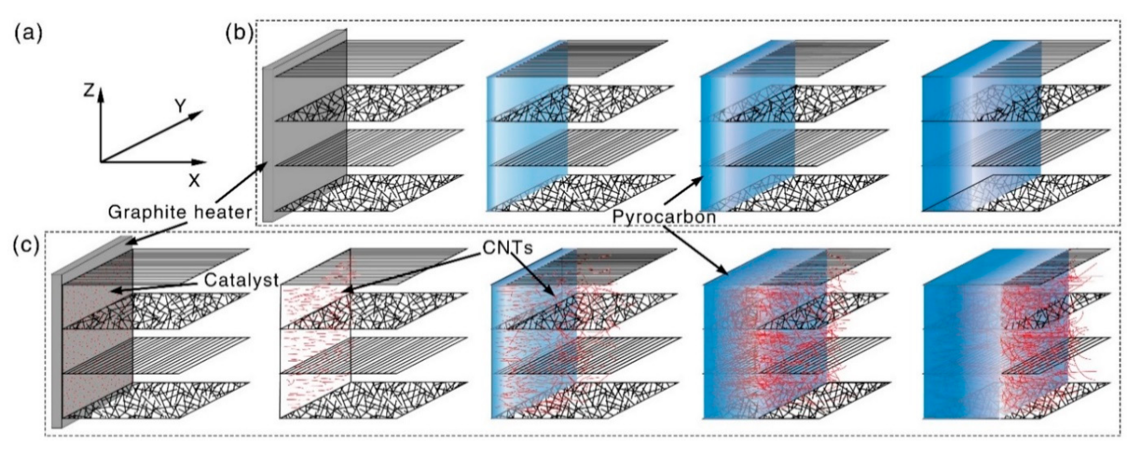
2.1. Preparation of C/C and CC/C Composites

A 2D needle-punched carbon fiber preform with a density of 0.4 g/cm3 was used initially to prepare CC/C composites and traditional C/C composites. The carbon fiber preform was fabricated by over-lapping layers of 0° non-woven carbon fiber cloth, short-cut fiber web and 90° non-woven carbon fiber cloth. These layers were repeated and vertically needle-punched (Z axis), as shown in Figure 1. The catalyst was located at one side of the 2D needle-punched carbon fiber preform adjacent to the graphite heater, as shown in Figure 1c. A controlled temperature gradient was manipulated by the electric current passed through the heater of a thermal gradient chemical vapor deposition machine. Due to the thermal gradient, the temperature decreased along the X axis; therefore, CNTs formed and grew up when the temperature was low and was not high enough to generate pyrocarbon matrix. With the temperature of the heater increasing, the low-temperature zone moved forward along the X axis, and the increased temperature promoted the generation of the pyrocarbon matrix required to densify the 2D needle-punched carbon fiber preform containing the previously grown CNTs. By ensuring the temperature gradually moved along the X axis, the whole 2D needle-punched carbon fiber preform could be densified into fabricated CC/C composites. The densification temperature was 705–1155 °C. Natural gas (with methane content 99%) was entered as the precursor of carbon, and its volume flow rate was 3–15 L/min. The densification process proceeded along the X axis. For comparison, pure C/C composites without CNTs were also prepared utilizing the same process, and the schematic diagram of the densification process is shown in Figure 1b.

2.2. Mechanical Properties

Mechanical properties of the fabricated CC/C composites and C/C composites were determined by a three-point bending test, compression test, and shear test on a SANS universal mechanical machine (CMT5304-30 kN and CMT5304-1 kN) at a constant speed of 0.2 mm/min. Rectangular bars with a dimension of 30 mm × 5 mm × 2 mm were cut from the composites to carry out the three-point bending test, and the span was 20 mm. Meanwhile, cubes of 10 mm × 6 mm × 6 mm and 5 mm × 4 mm × 4 mm were used to implement the compression test and shear test, respectively. The cutting and loading directions were defined as follows: the direction perpendicular to the over-lapping layers of 2D needle-punched carbon felts was labelled Z direction, and the direction parallel to the over-lapping layers of 2D needle-punched carbon felts was labelled X or Y direction.

2.3. Materials Characterizations

The density of the fabricated samples was measured by the Archimedes method in water. A Leica DMLP polarized light microscope (PLM, DMLP) was used to observe the textures of the obtained composites. The fracture surface morphology and microstructure were characterized by scanning with electron microscopes (SEM, Tescan Mira 3, Czech and ZEISS Supra 55) and transmission electron microscopes (TEM, FEI Tecnai F30 G2). Micro residual stress in the composites was analyzed by Raman G peak mapping using Raman spectroscopes (InVia, Renishaw, He-Ne laser, 532 nm).

3. Results

In the fracture morphologies (Figure 2a,b) and polarized light microscope (PLM) image (Figure 2c) of the traditional C/C composites, although the density reached 1.76 g/cm3 (with an open porosity of 6.5%), there were still many gaps that were not fully densified during the fabrication process, which were distributed between carbon fibers. The pyrocarbon matrix had a layered structure (the insert in Figure 2a), and cracks could be found in the annular layers. In Figure 1b, the gap lengths increased to hundreds of microns, representing potential cracks during fracturing. The PLM image (Figure 2c) illustrates that the pyrocarbon matrix in traditional C/C composites showed intense optical activity (high and medium texture), which was different from that of the carbon fibers [20,21,25,26], and indicates very different matrix structures between the fibers. The various structures of carbon usually have different properties. For example, the coefficient of thermal expansion (CTE) of high- and medium-texture pyrocarbon is larger than 10 × 10−6/°C [27], but it is less than 2 × 10⁻⁶/°C for carbon fibers [28]. As a result, the mismatching of CTE, induced by the different structures, could cause numerous cracks to emerge throughout the layered pyrocarbon matrix and between carbon fibers and pyrocarbon matrix [26,29,30], which will significantly influence the properties of C/C composites.
Although the density and open porosity of CC/C composites were less than 1.75 g/cm3 and 3.4%, respectively, there were few pores within them. Carbon fibers were compacted into the matrix, and no cracks or gaps were found in the CNT-reinforced pyrocarbon matrix (Figure 2d–f). No layered structure was found in the CC/C composites, and the matrix showed no growth orientation. In the fiber bundle (Figure 2e), the CNT-reinforced pyrocarbon matrix can completely fill the gaps between carbon fibers, and no cracks or gaps form between the fibers and the matrix. In the magnified fracture morphology (insert in Figure 2d), many micro-nano holes, which can be attributed to the CNT pull-out and the unfilled gaps between CNTs and the carbon matrix, could be found in the CNT-reinforced matrix. They were uniformly distributed throughout the matrix. The PLM image (Figure 2f) shows that the CC/C composites are compact, and both the CNT-reinforced pyrocarbon matrix and carbon fibers displayed low optical activity (low texture and isotropic). Therefore this indicates that they have a similar microstructure, which can reduce the mismatch of CTE between carbon fibers and the matrix.
Benefitting from the synchronous growth of CNTs and a pyrocarbon matrix, the CC/C composites can be fabricated more efficiently than C/C composites, and traditional CNT-reinforced C/C composites. As shown in Figure 3, the density of CC/C composites is much higher than that of C/C composites with the same densification time, and for the same density, the densification time of CC/C composites is shorter than that of C/C composites. In addition, for the traditional CNT-reinforced C/C composites, though the densification time is equal to that of the C/C composites, it is more costly timewise to carry out the growth of CNTs before the densification process. As a result of the impact of CNTs, its densification processing is more difficult than C/C composites, and more pores would be left in the fabricated CNT-reinforced C/C composites. However, the method proposed by this research can minimize the adverse effect of CNTs on the densification process and achieve an increased densification rate. As such, the proposed method is more efficient and low-cost than the traditional densification method. With a prolonged densification time, the fitted limit density of CC/C composites (1.86 g/cm3) is also larger than that of C/C composites (1.83 g/cm3).
In general, C/C composites with a higher density usually exhibit higher mechanical strength [30]. As shown in Figure 4, in this work, CC/C composites with a lower density of 1.75 g/cm3 exhibited a higher mechanical strength than those of C/C composites with a higher density of 1.80 g/cm3. The flexural strength (at X, Z directions), compression strength (at X, Z directions) and shear strength (at X, Z directions) were increased by 15.2%, 13.2%, 16.9%, 9.7%, 41.9%, 5.5%, respectively. This indicates that the CNT-reinforced pyrocarbon matrix, induced by a synchronous growth method, greatly improves the mechanical strength of CC/C composites. The hollow CNTs simultaneously decrease the density. Corresponding to the strength, the modulus of CC/C composites is also higher than that of C/C composites. This illustrates that the CNTs reinforced pyrocarbon matrix has a higher strength and modulus than the pyrocarbon matrix in C/C composites. Moreover, the load-displacement curves show little difference between the two composites, showing similar fracture processing.
Since the fabrication temperature was higher than 1000 °C and the CTE of pyrocarbon is much larger than that of carbon fibers along the radial direction, the intrinsic stress caused by the mismatching of CTE was inevitable between carbon fibers and the pyrocarbon matrix. Usually, Raman spectroscopy is an effective method to analyze the structure of carbon-based materials [31,32], and Raman mapping of the shift in the G peak is used to evaluate the stress distribution in and around carbon fibers [33]. As displayed in Figure 5a, before densification, there was no obvious difference in the Raman spectra of carbon fibers, and no stress was applied to the carbon fiber. After densification, the carbon fibers and matrix suffered the intrinsic stress caused by the mismatching of CTEs of the pyrocarbon matrix and carbon fibers. The G peak could shift toward higher (compressive stress) or lower frequencies (tensile stress) [34,35,36]. Figure 5b shows that the intensity ratio of D and G peaks (ID/IG) of CC/C composites is much larger than that of C/C composites, indicating that carbon atoms in the matrix of CC/C composites are much closer to a short-range order structure. Additionally, a 2D band of around 2700 cm−1 and D + G band of around 2950 cm−1 were detected. I2D/IG+D are usually indicators of texture. A higher I2D/IG+D mean a more ordered in-plane structure. Figure 5b shows that the structure of the carbon matrix of C/CC composites was more ordered than the traditional C/C composites. This indicates that the CNTs in the matrix improve the texture of C/CC composites. The results of the second order bands fit well with the first order bands. However, compared to that of the C/C composites, they have shifted a little and, therefore, could not be used as the reference point to evaluate the intrinsic stress. Therefore, the G peak of carbon fibers before densification (1590.4 cm−1 in Figure 5a) was used as the reference point to evaluate the intrinsic stress within the fabricated composites. Figure 5c,d demonstrates that the carbon fiber in C/C composites shows a significant difference from the matrix and the G peak has increased, indicating that the carbon fiber has suffered strong compressive stress. However, for the CC/C composites (Figure 5e,f), little difference is found between the carbon fiber and the matrix, indicating a smaller shift in the G peak for carbon fiber and low intrinsic stress in the fabricated CC/C composites.
In the thermal shock test, because of the different structures in C/C composites, cracks induced by the mismatching of CTE (carbon fibers: <2 × 10⁻⁶/°C [28] and pyrocarbon matrix: >10 × 10−6/°C [27]) would form in the composites. As shown in Figure 6a, cracks form in the pyrocarbon matrix after the thermal shock test, and carbon fibers are separated from the matrix. In Figure 6b, there is little difference in the shift in the G peak between the carbon fiber and the pyrocarbon matrix. This indicates that the intrinsic stress in carbon fibers is released during the thermal shock test due to of the formation of cracks. However, in CC/C composites (Figure 6c), no cracks form in the CNT-reinforced pyrocarbon matrix, and no obvious gaps form around the carbon fibers. The CTE of the CNT-reinforced pyrocarbon matrix is 6 × 10⁻⁶/°C (Figure 7), which is also higher than that of carbon fibers, but the mismatching of CTE between the two different structures is decreased. The Raman mapping of the shift in the G peak also shows ittle difference between the CNT-reinforced pyrocarbon matrix and carbon fibers in the CC/C composites (Figure 6d). As a result, less intrinsic stress exists in the CC/C composites, and fewer cracks are formed after the thermal shock test.
During the fabrication process of the CC/C composites, the temperature gradient, is not hot enough for pyrocarbon to be generated. Furthermore, due to the catalytic growth of the catalysts, CNTs can initiate and grow prematurely between carbon fibers within a limited area (Figure 8a,b). They randomly distribute within the carbon preform. The CNTs show a bamboo-like microstructure [37,38,39,40], and the typical outer and inner diameter for CNTs is ~200 and 100 nm (Figure 8c). Due to the in-site growth of CNTs, more sites are formed for the deposition of pyrocarbon, which could accelerate the densification rate of C/CC composites. Thus, the densification rate of C/CC composites would be much higher than C/C with the same process. As a result, the density of the fabricated CC/C composites was much higher than that of the traditional C/C composites with the same densification time (Figure 3).
The SEM images (Figure 9a–c) of the fracture show that the pyrocarbon matrix in C/C composites forms layered structures around the carbon fibers, and many gaps separate them. The reason for this is that, perpendicular to the direction of the layered pyrocarbon, the CTE is much higher than that of the parallel direction and carbon fibers. As a result, when it suffers thermal shock, cracks are easily generated in the layered pyrocarbon matrix. For CC/C composites (Figure 9d), many CNTs are pulled out and holes are distributed on the fracture surface. In addition, the pyrocarbon matrix completely fills the space between carbon fibers. The fracture surface of the CNT-reinforced pyrocarbon matrix is much rougher than that of C/C composites. As illustrated in the TEM image (Figure 9e), CNTs display a bamboo-like microstructure and remain intact in the matrix, which results in the mechanical properties of CC/C composites. As shown in the high-resolution TEM (HRTEM) image and the selected area electron diffraction (SAED) pattern (Figure 9f), the pyrocarbon matrix is composed of randomly oriented micro- and nano-crystals and amorphous carbon. In this way, the hollow CNTs in the pyrocarbon matrix can increase the mechanical properties and reduce the density of the C/C composites.

4. Conclusions

In conclusion, we report a novel method of fabricating CNT-reinforced C/C composites by densifying a 2D needle-punched carbon fiber preform with the synchronous growth of CNTs and a pyrocarbon matrix. During the densifying process, CNTs form at the relatively low-temperature zone ahead of the densifying zone, so they have little influence on the gas transmission of carbon sources in a 2D needle-punched carbon fiber preform. The preform ensures that the carbon sources can diffuse into the densifying zone that includes CNTs and carbon fibers, avoiding the densification that occurs in a wide space, which could create many holes in C/C composites. Compared with the fabrication process of traditional C/C and CNT-reinforced C/C composites, the CC/C composites fabricated by the proposed method have low density, low open porosity, and improved mechanical properties, which makes the fabrication of high-performance CNT-reinforced C/C composites more efficient. This research provides an impressive and novel structural design strategy for the highly efficient preparation of high-performance C/C composites, which could potentially be used to manufacture aircraft materials that need to withstand high temperatures.

Author Contributions

Conceptualization, N.L. and G.K.; methodology, N.L.; formal analysis, G.K.; investigation, N.L.; data curation, N.L.; writing—original draft preparation, N.L.; writing—review and editing, X.Y.; supervision, L.G.; project administration, L.G.; funding acquisition, L.G. and Y.L. All authors have read and agreed to the published version of the manuscript.

Funding

This research was funded by the National Natural Science Foundation of China (Grant No. 52072305, 51727804 and 91860203) and Shaanxi Province Postdoctoral Science Foundation (Grant No. 2017BSHEDZZ12).

Institutional Review Board Statement

Not applicable.

Informed Consent Statement

Not applicable.

Data Availability Statement

Data Sharing is not applicable.

Acknowledgments

N.K. Liu and G. Kou contributed equally to this work. We also would like to thank the Analytical & Testing Center of Northwestern Polytechnical University for TEM and SEM.

Conflicts of Interest

The authors declare no conflict of interest.

References

  1. Fu, Q.; Zhang, P.; Zhuang, L.; Zhou, L.; Zhang, J.; Wang, J.; Hou, X.; Riedel, R.; Li, H. Micro/nano multiscale reinforcing strategies toward extreme high-temperature applications: Take carbon/carbon composites and their coatings as the examples. J. Mater. Sci. Technol. 2021, 96, 31–68. [Google Scholar] [CrossRef]
  2. Li, L.; Li, H.; Li, Y.; Yin, X.; Shen, Q.; Fu, Q. A SiC-ZrB2-ZrC coating toughened by electrophoretically-deposited SiC nanowires to protect C/C composites against thermal shock and oxidation. Appl. Surf. Sci. 2015, 349, 465–471. [Google Scholar] [CrossRef]
  3. He, Q.; Li, H.; Yin, X.; Lu, J. Effects of PyC shell thickness on the microstructure, ablation resistance of SiCnws/PyC-C/C-ZrC-SiC composites. J. Mater. Sci. Technol. 2021, 71, 55–66. [Google Scholar] [CrossRef]
  4. Xiao, P.; Lu, X.-f.; Liu, Y.; He, L. Effect of in situ grown carbon nanotubes on the structure and mechanical properties of unidirectional carbon/carbon composites. Mat. Sci. Eng. A Struct. 2011, 528, 3056–3061. [Google Scholar] [CrossRef]
  5. Gong, Q.-M.; Li, Z.; Bai, X.-D.; Li, D.; Liang, J. The effect of carbon nanotubes on the microstructure and morphology of pyrolytic carbon matrices of C-C composites obtained by CVI. Compos. Sci. Technol. 2005, 65, 1112–1119. [Google Scholar] [CrossRef]
  6. Wang, R.; Xie, L.; Hameed, S.; Wang, C.; Ying, Y. Mechanisms and applications of carbon nanotubes in terahertz devices: A review. Carbon 2018, 132, 42–58. [Google Scholar] [CrossRef]
  7. Zhang, S.; Ma, Y.; Suresh, L.; Hao, A.; Bick, M.; Tan, S.C.; Chen, J. Carbon nanotube reinforced strong carbon matrix composites. ACS Nano 2020, 14, 9282–9319. [Google Scholar] [CrossRef] [PubMed]
  8. Feng, L.; Li, K.; Zhao, Z.; Li, H.; Zhang, L.; Lu, J.; Song, Q. Three-dimensional carbon/carbon composites with vertically aligned carbon nanotubes: Providing direct and indirect reinforcements to the pyrocarbon matrix. Mater. Des. 2016, 92, 120–128. [Google Scholar] [CrossRef]
  9. Gong, Q.-M.; Li, Z.; Zhou, X.-W.; Wu, J.-J.; Wang, Y. Synthesis and characterization of in situ grown carbon nanofiber/nanotube reinforced carbon/carbon composites. Carbon 2005, 43, 2426–2429. [Google Scholar] [CrossRef]
  10. Kou, G.; Guo, L.-J.; Li, Z.-Q.; Peng, J.; Tian, J.; Huo, C.-X. Microstructure and flexural properties of C/C-Cu composites strengthened with in-situ grown carbon nanotubes. J. Alloys Compd. 2017, 694, 1054–1060. [Google Scholar] [CrossRef]
  11. Feng, L.; Li, K.-Z.; Si, Z.-S.; Song, Q.; Li, H.-J.; Lu, J.-H.; Guo, L.-J. Compressive and interlaminar shear properties of carbon/carbon composite laminates reinforced with carbon nanotube-grafted carbon fibers produced by injection chemical vapor deposition. Mat. Sci. Eng. A Struct. 2015, 626, 449–457. [Google Scholar] [CrossRef]
  12. González, I.; De Jesus, J.; Cañizales, E. Bamboo-shaped carbon nanotubes generated by methane thermal decomposition using Ni nanoparticles synthesized in water–oil emulsions. Micron 2011, 42, 819–825. [Google Scholar] [CrossRef]
  13. Gao, X.; Liu, L.; Guo, Q.; Shi, J.; Zhai, G. Fabrication and mechanical/conductive properties of multi-walled carbon nanotube (MWNT) reinforced carbon matrix composites. Mater. Lett. 2005, 59, 3062–3065. [Google Scholar] [CrossRef]
  14. Chen, J.; Xiong, X.; Xiao, P. The effect of carbon nanotube growing on carbon fibers on the microstructure of the pyrolytic carbon and the thermal conductivity of carbon/carbon composites. Mater. Chem. Phys. 2009, 116, 57–61. [Google Scholar] [CrossRef]
  15. Kamedulski, P.; Lukaszewicz, J.P.; Witczak, L.; Szroeder, P.; Ziolkowski, P. The Importance of Structural Factors for the Electrochemical Performance of Graphene/Carbon Nanotube/Melamine Powders towards the Catalytic Activity of Oxygen Reduction Reaction. Materials 2021, 14, 2448. [Google Scholar] [CrossRef] [PubMed]
  16. Krieg, A.S.; King, J.A.; Odegard, G.M.; Leftwich, T.R.; Odegard, L.K.; Fraley, P.D.; Miskioglu, I.; Jolowsky, C.; Lundblad, M.; Park, J.G. Mechanical Properties and Characterization of Epoxy Composites Containing Highly Entangled As-Received and Acid Treated Carbon Nanotubes. Nanomaterials 2021, 11, 2445. [Google Scholar] [CrossRef]
  17. Han, L.; Song, Q.; Sun, J.; Li, K.; Lu, Y. The role of CNT in improving the mechanical strength retention rate of C/C composites during heat treatment. Compos. Part B Eng. 2020, 187, 107856. [Google Scholar] [CrossRef]
  18. Fan, W.; Wang, Y.; Wang, C.; Chen, J.; Wang, Q.; Yuan, Y.; Niu, F. High efficient preparation of carbon nanotube-grafted carbon fibers with the improved tensile strength. Appl. Surf. Sci. 2016, 364, 539–551. [Google Scholar] [CrossRef]
  19. Zhao, J.-G.; Li, K.-Z.; Li, H.-J.; Wang, C. The influence of thermal gradient on pyrocarbon deposition in carbon/carbon composites during the CVI process. Carbon 2006, 44, 786–791. [Google Scholar] [CrossRef]
  20. Li, W.; Li, H.-J.; Wang, J.; Zhang, S.-Y.; Xi, Y.; Wei, J.-F. Preparation and mechanical properties of carbon/carbon composites with high textured pyrolytic carbon matrix. T. Nonferr. Metal. Soc. 2013, 23, 2129–2134. [Google Scholar] [CrossRef]
  21. Feng, L.; Li, K.; Sun, J.; Jia, Y.; Li, H.; Zhang, L. Influence of carbon nanotube extending length on pyrocarbon microstructure and mechanical behavior of carbon/carbon composites. Appl. Surf. Sci. 2015, 355, 1020–1027. [Google Scholar] [CrossRef]
  22. Kou, G.; Guo, L.-J.; Li, H.-J. Effect of copper on the heat erosion mechanism of carbon/carbon composites. J. Alloys Compd. 2017, 723, 1132–1141. [Google Scholar] [CrossRef]
  23. Kou, G.; Guo, L.-J.; Liu, N.-K.; Chen, M.-M.; Xu, M.; Zhao, Z.-G. Significant influence of Al2O3 on the flexural properties of C/C composites. Vacuum 2018, 151, 294–297. [Google Scholar] [CrossRef]
  24. Zhang, H.; Guo, L.; Song, Q.; Fu, Q.; Li, H.; Li, K. Microstructure and flexural properties of carbon/carbon composite with in-situ grown carbon nanotube as secondary reinforcement. Prog. Nat. Sci. Mater. 2013, 23, 157–163. [Google Scholar] [CrossRef] [Green Version]
  25. Guellali, M.; Oberacker, R.; Hoffmann, M. Influence of the matrix microstructure on the mechanical properties of CVI-infiltrated carbon fiber felts. Carbon 2005, 43, 1954–1960. [Google Scholar] [CrossRef]
  26. Jia, Y.; Li, K.; Zhang, S.; Li, L.; Ren, J. Microstructure and mechanical properties of multilayer-textured 2D carbon/carbon composites. J. Mater. Sci. Technol. 2014, 30, 1202–1207. [Google Scholar] [CrossRef]
  27. Piat, R.; Schnack, E. Modeling the effect of microstructure on the coefficients of thermal expansion of pyrolytic carbon. Carbon 2003, 41, 2162–2165. [Google Scholar] [CrossRef]
  28. Honjo, K. Fracture toughness of PAN-based carbon fibers estimated from strength–mirror size relation. Carbon 2003, 41, 979–984. [Google Scholar] [CrossRef]
  29. Xia, L.; Huang, B.; Zhang, F.; Liu, Z.; Chen, T. Effect of heat treatment on cracking and strength of carbon/carbon composites with smooth laminar pyrocarbon matrix. Mater. Des. 2016, 107, 33–40. [Google Scholar] [CrossRef]
  30. Cao, W.-F.; Li, H.-J.; Guo, L.-J.; Zhang, S.-Y.; Li, K.-Z.; Deng, H.-L. Fracture mechanism of 2D-C/C composites with pure smooth laminar pyrocarbon matrix under flexural loading. T. Nonferr. Metal. Soc. 2013, 23, 2141–2146. [Google Scholar] [CrossRef]
  31. Yin, X.; Li, H.; Han, L.; Meng, J.; Lu, J.; Zhang, L.; Li, W.; Fu, Q.; Li, K.; Song, Q. Lightweight and flexible 3D graphene microtubes membrane for high-efficiency electromagnetic-interference shielding. Chem. Eng. J. 2020, 387, 124025. [Google Scholar] [CrossRef]
  32. Yin, X.; Li, H.; Han, L.; Meng, J.; Lu, J.; Song, Q. All Si3N4 Nanowires Membrane Based High-Performance Flexible Solid-State Asymmetric Supercapacitor. Small 2021, 17, 2008056. [Google Scholar] [CrossRef] [PubMed]
  33. Pu, J.; Guo, L.; Song, Q.; Zhang, X.; Liu, B.; Zeng, Q.; Li, Y.; Yin, X.; Yan, N.; Meng, J. Orthogonally structured graphene nanointerface for lightweight SiC nanowire-based nanocomposites with enhanced mechanical and electromagnetic-interference shielding properties. Compos. Part B Eng. 2020, 202, 108381. [Google Scholar] [CrossRef]
  34. Taylor, C.A.; Wayne, M.F.; Chiu, W.K. Heat treatment of thin carbon films and the effect on residual stress, modulus, thermal expansion and microstructure. Carbon 2003, 41, 1867–1875. [Google Scholar] [CrossRef]
  35. López-Honorato, E.; Meadows, P.; Shatwell, R.; Xiao, P. Characterization of the anisotropy of pyrolytic carbon by Raman spectroscopy. Carbon 2010, 48, 881–890. [Google Scholar] [CrossRef]
  36. Veres, M.; Tóth, S.; Koós, M. New aspects of Raman scattering in carbon-based amorphous materials. Diamond Relat. Mater. 2008, 17, 1692–1696. [Google Scholar] [CrossRef]
  37. Lu, Y.; Zhu, Z.; Su, D.; Wang, D.; Liu, Z.; Schlögl, R. Formation of bamboo-shape carbon nanotubes by controlled rapid decomposition of picric acid. Carbon 2004, 42, 3199–3207. [Google Scholar] [CrossRef] [Green Version]
  38. Zhao, N.; He, C.; Ding, J.; Zou, T.; Qiao, Z.; Shi, C.; Du, X.; Li, J.; Li, Y. Bamboo-shaped carbon nanotubes produced by catalytic decomposition of methane over nickel nanoparticles supported on aluminum. J. Alloys Compd. 2007, 428, 79–83. [Google Scholar] [CrossRef]
  39. Yin, X.; Li, H.; Han, L.; Yuan, R.; Lu, J. NiCo2O4 nanosheets sheathed SiC@CNTs core-shell nanowires for high-performance flexible hybrid supercapacitors. J. Colloid Interf. Sci. 2020, 577, 481–493. [Google Scholar] [CrossRef] [PubMed]
  40. Han, L.; Song, Q.; Li, K.; Yin, X.; Sun, J.; Li, H.; Zhang, F.; Ren, X.; Wang, X. Hierarchical, seamless, edge-rich nanocarbon hybrid foams for highly efficient electromagnetic-interference shielding. J. Mater. Sci. Technol. 2021, 72, 154–161. [Google Scholar] [CrossRef]
Figure 1. (a) Directions of the layered 2D needle-punched carbon fiber preform, the densification process was along X axis; Densification process of (b) traditional C/C composites and (c) CC/C composites.
Materials 14 06607 g001
Figure 2. SEM images and PLM images of (ac) C/C and (df) CC/C composites: (a,d) SEM images of carbon fibers perpendicular to fracture surface; (b,e) SEM images of carbon fibers parallel to fracture surface; (c,f) PLM images.
Materials 14 06607 g002
Figure 3. (a) Density and fitted limit density of CC/C and traditional C/C composites; (b) Porosity and fitted limit porosity of CC/C and traditional C/C composites.
Materials 14 06607 g003
Figure 4. Mechanical properties of CC/C and traditional C/C composites: (a,b) Three-point bending test; (c,d) Compression test; (e,f) Shear test.
Materials 14 06607 g004
Figure 5. Raman spectra analysis: (a) Carbon fibers in C/C and CC/C composites before densification; (b) Matrix in C/C (Point 1) and CC/C (Point 2) composites after densification process; (c,e) Optical micrographs of C/C and CC/C composites; (d,f) Raman mapping of the shift of G peak, reflecting the stress distribution in carbon fiber in C/C and CC/C composites.
Materials 14 06607 g005
Figure 6. Raman spectra analysis after thermal shock test of (a,c) C/C and (b,d) CC/C composites: (a,b) Optical micrographs; Raman mapping of the shift in G peak, reflecting the stress distribution in carbon fiber.
Materials 14 06607 g006
Figure 7. CTE of the CNTs reinforced pyrocarbon matrix of CC/C composites.
Materials 14 06607 g007
Figure 8. (a,b) SEM and (c) TEM images of CNTs in 2D needle-punched carbon fiber preform.
Materials 14 06607 g008
Figure 9. (ac) Fracture morphology of C/C composites; (d) Fracture morphology of CC/C composites; (e) TEM image of the CNTs reinforced pyrocarbon matrix in CC/C composites; (f) HRTEM image of Pyrocarbon matrix in the CC/C composites (Insert f is the SAED).
Materials 14 06607 g009
Publisher’s Note: MDPI stays neutral with regard to jurisdictional claims in published maps and institutional affiliations.

