Abstract
To investigate the growth kinetics of the reaction layer and mechanical strength of joined materials, we joined beryllium and reduced-activation ferritic–martensitic steel (F82H) by plasma sintering under various conditions and characterized the joined region. Scanning electron microscopy revealed that the thickness of the reaction layer increased with an increase in the joining time and temperature. Line analyses and elemental mapping using an electron microprobe analyser showed that the reaction layer consists of Be–Fe intermetallic compounds, including Be12Fe, Be5Fe, and Be2Fe, with small amounts of chromium and tungsten. Owing to the time and temperature dependence of the reaction-layer thickness, the layer growth of Be–Fe intermetallic compounds obeys the parabolic law, and the activation energy for the reaction-layer growth was 116.2 kJ/mol. The bonding strengths of the joined materials varied inversely with the thickness of the reaction layer.
1. Introduction
Great attention has been paid to technologies for joining materials, including metals, ceramics, polymers, and composites. Joining processes are promising techniques to improve specific properties, such as structural strengths and functional properties; the joined materials show more excellent properties than the individual materials [1,2]. Several techniques have been proposed for joining metals, including metallic brazing [3], welding [4], plasma spraying [5], and coating [6].
For fusion applications, beryllium (Be) is used as an amour for the first wall in an International Thermonuclear Experimental Reactor (ITER) owing to the advantages of low-atomic-number (Z) materials, including reduced impurity content, low loss of plasma radiation, and absence of chemical sputtering. However, Be forms intermetallic compounds with iron (Fe) [7], which may reduce the strength of the joint area since intermetallic compounds are considerably brittle.
Efforts have been made to simplify the blanket design [8] by replacing the pebbles with block-shaped neutron-multiplying materials. This can also reduce the fraction of structural steel, which may contribute to plasma disruption or electromagnetic issues. When neutron-multiplying materials are used as block shapes by partial replacement of structural materials, the obtained material has good bonding strength to structural materials, such as reduced-activation ferritic–martensitic steel. Supposing the operating temperature is not high, Be can be considered the first wall material and as a block-shaped material in the blanket region of the fusion reactor to increase the neutron-multiplying efficiency.
Hot-isostatic-press (HIP) joining Be and F82H (Japanese reduced-activation ferritic–martensitic steel) has been conducted, and the thickness and bonding strengths of the reaction layers, such as thin Cr [9] and Ti films [10] have been investigated. The authors have, for the first time globally, fabricated Be [11,12] and beryllium intermetallic compounds [13,14,15] by plasma sintering, which is an advantageous process including surface activation for cleaning, and rapid heating and cooling speeds.
In this study, to clarify the growth kinetics of reaction layers and investigate the interfacial properties between joint areas, Be and F82H were joined by plasma sintering at various temperatures, and the mechanical properties of the joined materials were tested.
2. Materials and Methods
The starting material was F82H (Fe–8Cr–2W–0.2V–0.04Ta–0.1C), which is a candidate structural material for a Japanese test blanket material and demonstration (DEMO) reactor. The F82H (BA12 heat, ID:BT2-1-4) was treated by normalizing at 1313 K for 40 min and then tempered at 1023 °C for 60 min after hot rolling of an ingot material, and consisted of a tempered martensite structure [16]. The material was machined to a thickness of 17 mm and diameter of 20 mm with cutting accuracy of ±1 μm by an electrical discharge machine (Robocut α-OiD, FANUC, Yamanashi, Japan). Be materials (S65, Materion, Mayfield Heights, OH, USA) of the same thickness and diameter were machined to a cylindrical rod with a diameter of 20 mm and thickness of 17 mm. The joining areas of both F82H and Be samples were polished by up to #4000 silicon carbide (SiC) paper. To perform joining of two cylindrical materials, a plasma sintering (KE-PAS III, KAKEN Co., Ltd., Ibaraki, Japan) process was applied. After the two materials were placed in a graphite punch-and-die system, the Be and F82H samples were joined by plasma sintering at different sintering temperatures (923, 1023, and 1123 K) and at a pressure of 50 MPa for 90 min. To investigate the interfacial difference in the cross-section of the Be–F82H joint and the variation in the composition of the reaction layer, electron probe microscopic analysis (JXA-8530F, JEOL, Tokyo, Japan) with point and line analyses was conducted. In parallel to the point and line analyses, elemental mapping was conducted on the reaction layer with Fe, Cr, W, and Be.
To evaluate the mechanical properties of joined materials, four-point bending tests were conducted by an universal tester (AGX-10kNVD, Shimadzu, Kyoto, Japan), based on JIS R1601 with a crosshead speed of 0.5 mm/min at room temperature using three samples per each condition of dimensions 3 mm × 3 mm × 35 mm, and polished using #1200 SiC paper. Furthermore, the fractural surface was observed by scanning electron microscopy (SEM)/EPMA (JXA-8530F, JEOL, Tokyo, Japan) to clarify the fracture behaviour of the joined samples.
3. Results and Discussion
Figure 1 shows the cross-sectional SEM images of the Be–F82H interfacial region joined by plasma sintering at 1023 K for 30, 60, and 90 min. The reaction layers between Be and F82H joined by plasma sintering under all conditions were observed. The thickness of the reaction layers increased as time increased. For the material joined at 1023 K for 30, 60, and 90 min, the reaction layer thickness was 7.2, 9.3, and 12.8 μm, respectively.

Figure 1.
Cross-sectional SEM images of Be–F82H joints sintered at 1023 K for (a) 30 min, (b) 60 min, and (c) 90 min.
To understand the temperature dependence of the reaction layer, the thicknesses of the reaction layers for the materials joined at 923, 1023, and 1123 K for 90 min were investigated, and the thickness was 6.8, 12.8, and 26.4 μm, respectively (Figure 2).

Figure 2.
Cross-sectional SEM images of Be–F82H joints sintered at (a) 923 K, (b) 1023 K, and (c) 1123 K for 90 min.
The thickness of a reaction layer between Be and F82H fabricated by the HIP process at 1023 K for 2 h was 6 μm [17], which slightly differs from the result herein. We speculate that plasma sintering facilitates the diffusion reaction more effectively than HIP since on–off direct current (DC) pulse promotes the sintering process, including effective discharge between particles of powder which leads to an electric field diffusion effect [18,19].
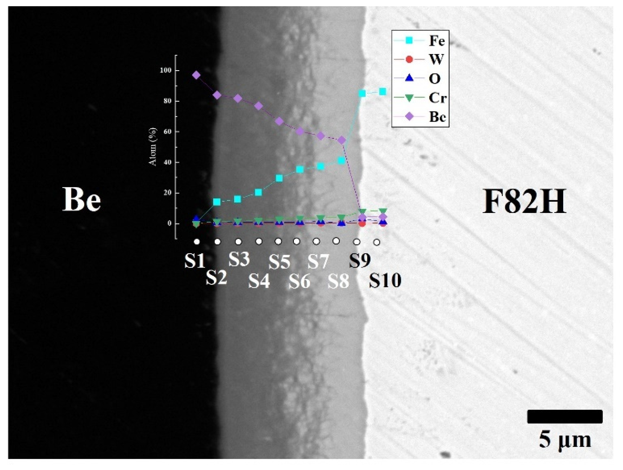
To clarify the chemical composition of the reaction layers, SEM observation with backscattered electrons and point analyses were performed on the layers (Figure 3). The reaction layer consists mainly of Be and Fe elements and small amounts of Cr and W. The concentration gradient of Fe and Be was determined. This concentration gradient is attributed to the formation of different intermetallic compounds, including Be12Fe, Be5Fe, and Be2Fe (Table 1). The Be-enriched compounds detected at the measurement points went into the Be matrix.
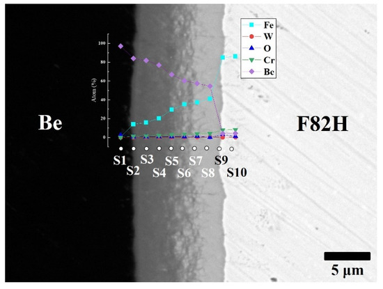
Figure 3.
Cross-sectional SEM image of F82H–Be joints sintered at 1023 K for 60 min with point analyses from S1 to S10 with atomic % of Fe, W, O, Cr and Be.

Table 1.
Chemical composition (at.%) of each point and estimated compounds.
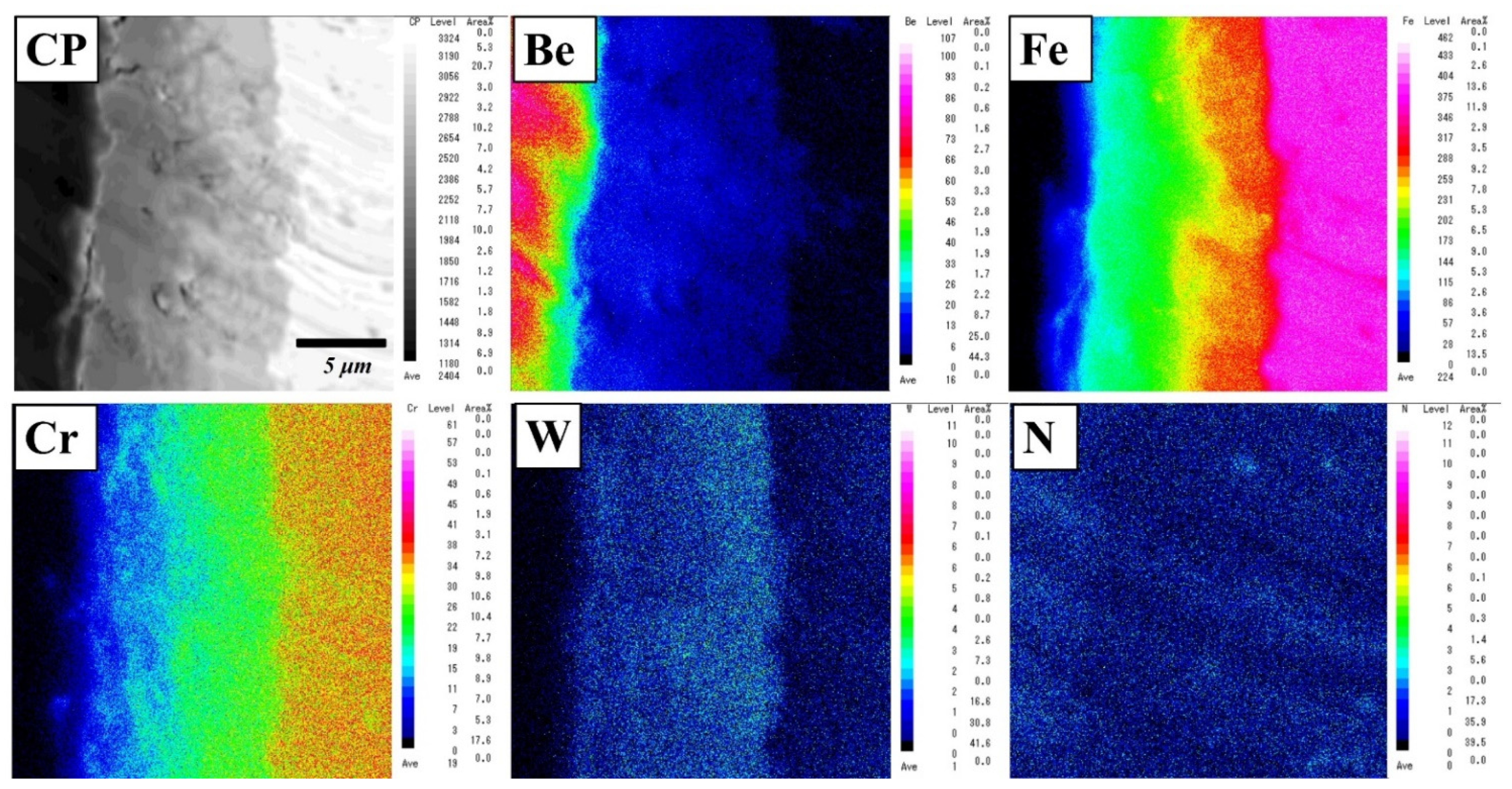
The analytical result is consistent with the elemental mapping of Be, Fe, Cr, W, and N elements using an electron microprobe analyser (EPMA) (Figure 4). The concentration gradient was dependent on the thickness of the layer. In the reaction layer, two or three layers with different compositions were identified. Be12Fe, Be5Fe, and Be2Fe with small amounts of Cr and W were detected (Table 1). Additionally, concentration gradients of Cr and W diffused from F82H were observed on the reaction layer. No remarkable depletion area was observed near the reaction layer.
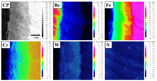
Figure 4.
Elemental mapping of a reaction layer in a Be–F82H joint sintered at 1023 K for 90 min.
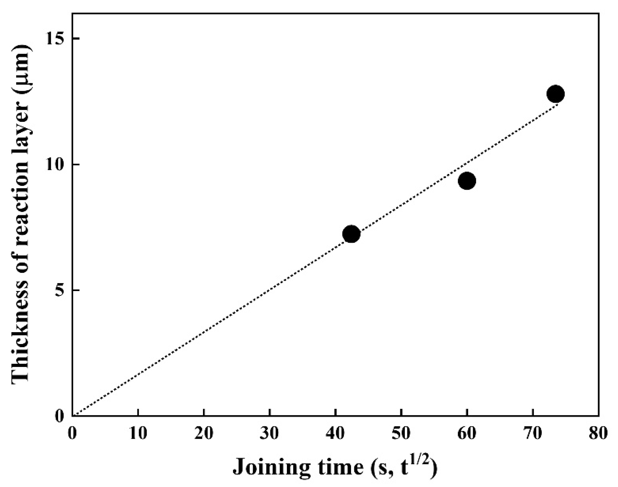
Since diffusion generally depends on time and temperature, it is vital to understand the joining time and temperature effect on the thickness of the reaction layer. Thus, the time dependence of the thickness of the reaction layer at 1023 K was investigated (Figure 5). The thickness of the reaction layer formed by reaction diffusion was proportional to the square root of the diffusion time (s), which is in good agreement with the results of previous studies [20,21]. The fitting result shows good linearity, implying the layer growth obeys the parabolic law, indicative of a diffusion-controlled growth, expressed as l = k·t1/2.
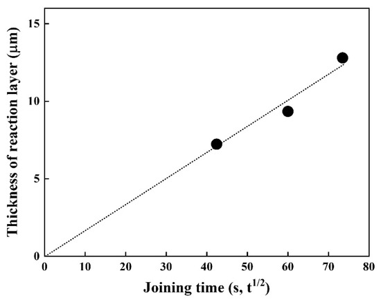
Figure 5.
Thickness of the reaction layer as a function of joining time at 1023 K.
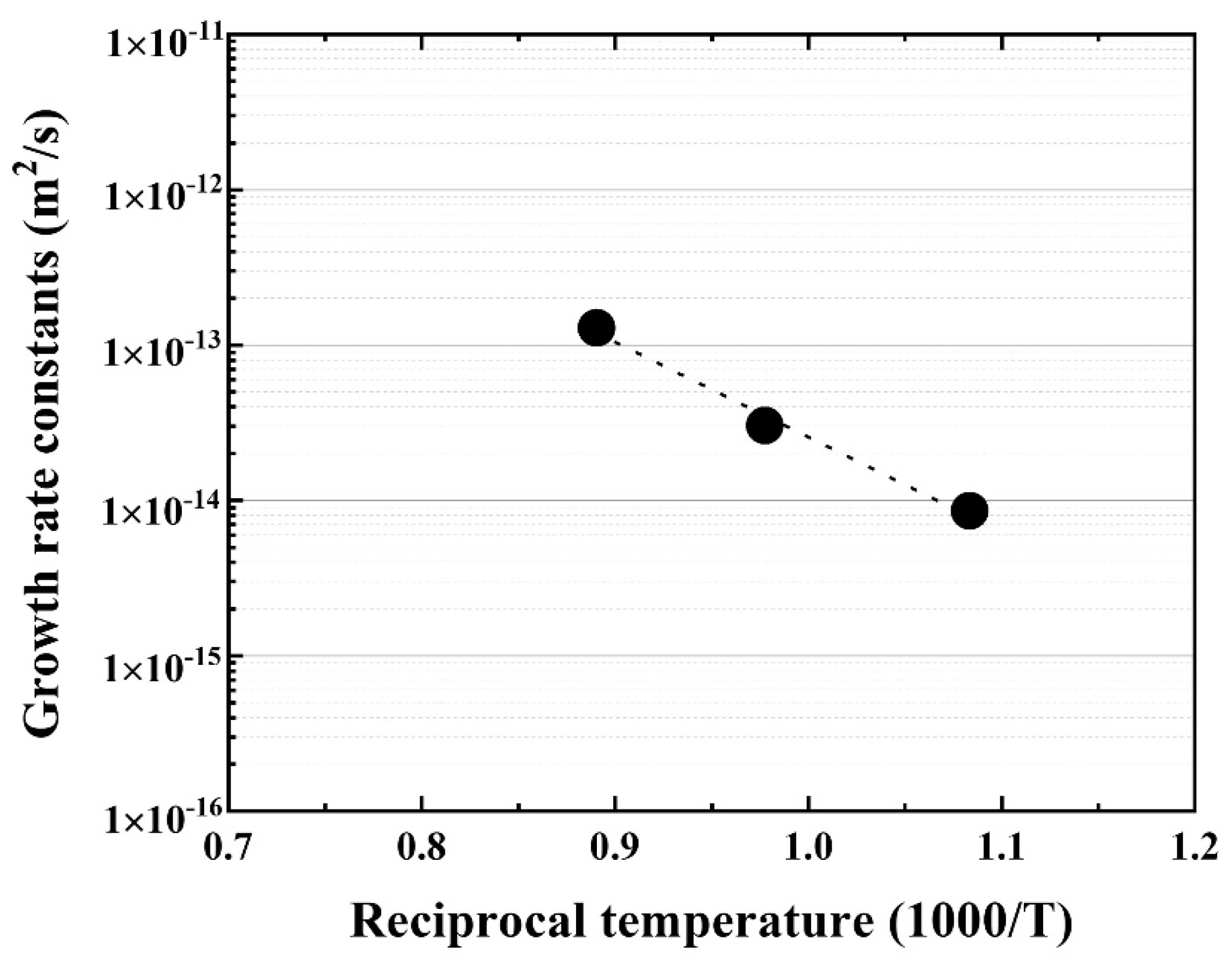
Further, the temperature dependence of the reaction layer was evaluated using the materials joined at 923, 1023, 1123 K for 90 min, and the growth rate constant (m2·s) was calculated. The Arrhenius plot of the growth rate constants for the reaction layer is shown in Figure 6.
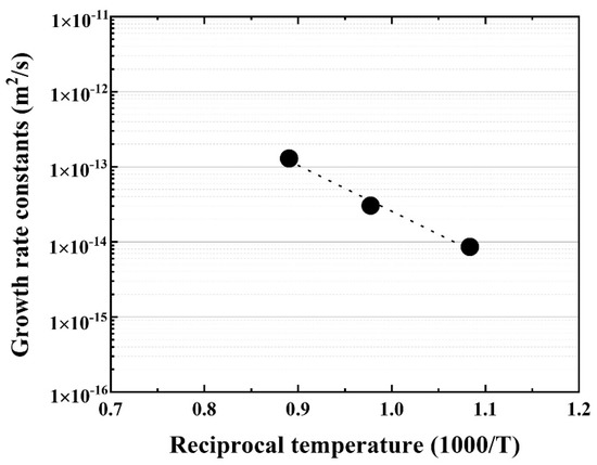
Figure 6.
Arrhenius plot of the reaction layer as a function of reciprocal temperature.
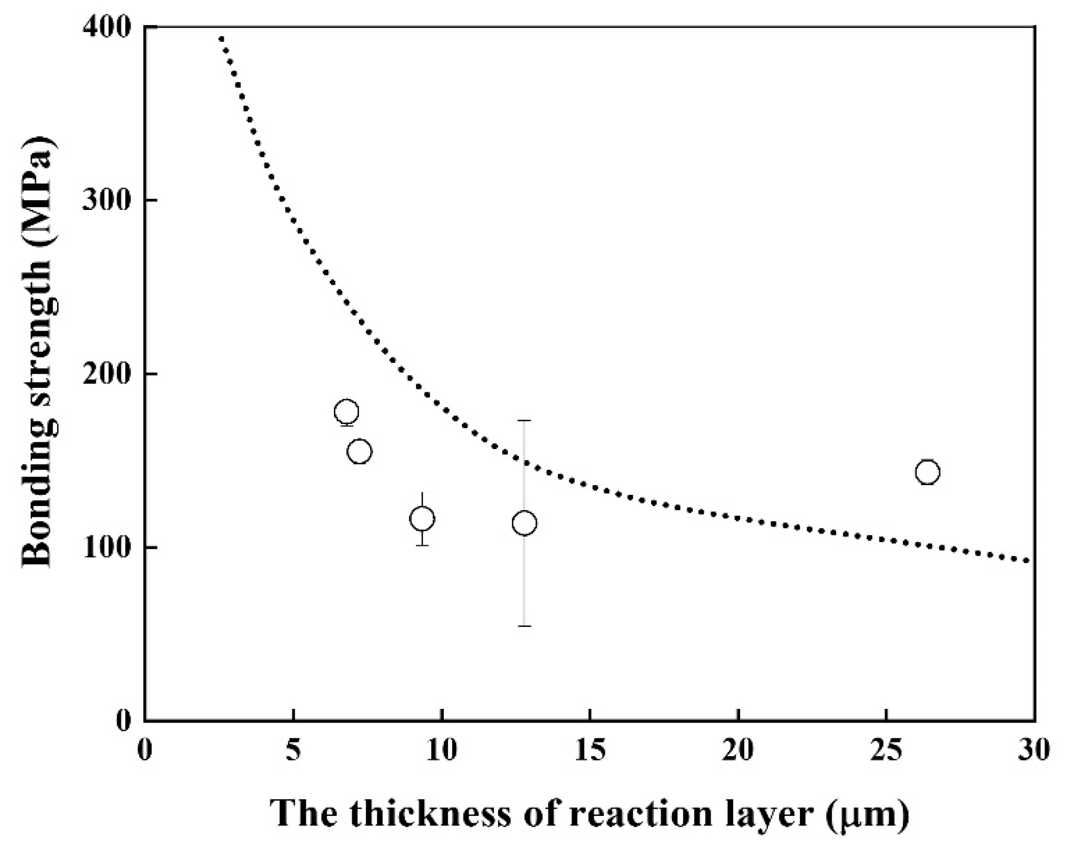
Good linearity was obtained, and the activation energy for the growth rate of the reaction layer was 116.2 kJ/mol, which is similar to that of Cu–Al intermetallic compound [22] and lower than that of β–Ti in Ti alloys [20]. The bonding strength of the Be/F82H joint was evaluated (Figure 7). It indicates that the bonding strength is inversely proportional to the thickness of the joint between Be and F82H. This inverse trend is because the increased thickness of the reaction layer comprising Be12Fe, Be5Fe, and Be2Fe decreased the bonding strength, which is in good agreement with the results in [17]. It is noted that all specimens were fractured at the joined area, in other words, it does not depend on the structure variation of the substrates, F82H and Be, even though those specimens were heat-treated at a temperature higher than the tempering temperature at 1023 K.
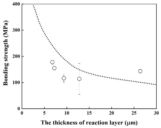
Figure 7.
Bonding strength of joints as a function of the reaction layer thickness (Dot line indicates the result in [17]).
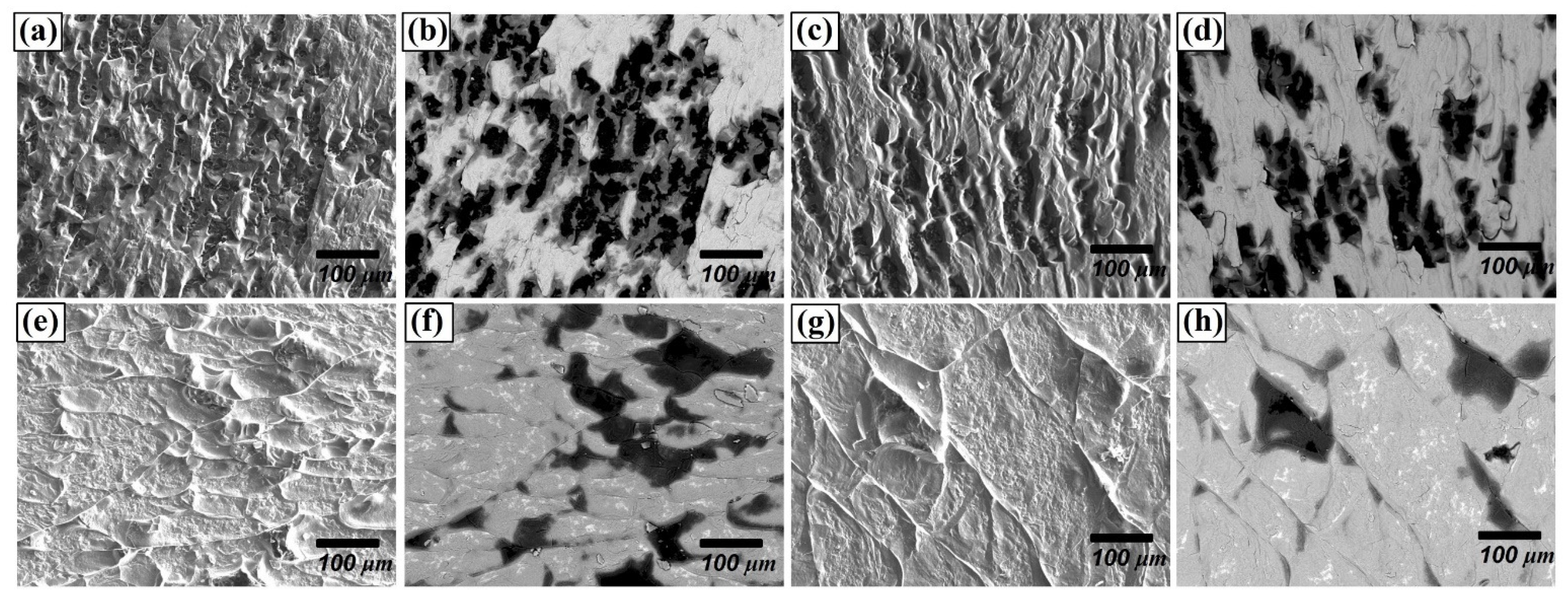
Regarding the fracture surface, for the materials joined for 30 min, many small-size grains were delaminated (Figure 8b) as seen with black colour. However, as the joining time and temperature increased, delaminations along the grain boundaries and the cleavage facets were observed. (Figure 8e,g), whereas the fraction of grain delamination decreased. This difference in delamination behaviour can be attributed to the variation in the bonding strength. It can be concluded that the increased thickness of the reaction layer comprising Be12Fe, Be5Fe, and Be2Fe decreased the bonding strength, since the intermetallic compounds are much more brittle than substrates.
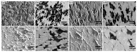
Figure 8.
Fracture surface of F82H–Be joint at 1023 K for (a,b) 30 min, (c,d) 60 min, (e,f) 90 m, and (g,h) 1123 K for 90 min, (a,c,e,g: secondary electron images, b,d,f,h: backscattered electron images).
4. Conclusions
Be and F82H were joined under various conditions to investigate the growth kinetics of the reaction layer and the mechanical strength of joined materials. As the joining time and temperature increased, the thickness of the reaction layer increased. Line analyses and elemental mapping by EPMA revealed that the reaction layer consists of Be–Fe intermetallic compounds, including Be12Fe, Be5Fe, and Be2Fe, with small amounts of Cr and W diffused from the F82H matrix.
Owing to the time dependence of the thickness of the reaction layer, the layer growth of Be–Fe intermetallic compounds predominantly obeys the parabolic law. Furthermore, by evaluating the temperature dependence of the thickness of the reaction layer, we found good linearity, and the activation energy for the growth of the reaction layer was 116.2 kJ/mol.
Finally, the bonding strength of the joined materials was inversely proportional to the thickness of the reaction layer. The difference in the fracture behaviour induced by either the delamination of grains or delamination along grain boundaries is attributed to the difference in the bonding strength.
Author Contributions
Conceptualization, J.-H.K. and T.H.; methodology, J.-H.K. and T.H.; validation, J.-H.K.; formal analysis, T.H.; writing-original draft preparation, J.-H.K.; writing-review and editing, J.-H.K. and T.H.; supervision, M.N. All authors have read and agreed to the published version of the manuscript.
Funding
This work was supported by JSPS KAKENHI Grant Number 21H01071.
Institutional Review Board Statement
Not applicable.
Informed Consent Statement
Not applicable.
Data Availability Statement
Not applicable.
Conflicts of Interest
The authors declare no conflict of interest.
References
- Miriyev, A.; Grutzner, S.; Kruger, L.; Kalabukhov, S.; Frage, N. Bonding of TRIP-steel/Al2O3-(3Y)-TZP composites and (3Y)-TZP ceramic by a spark plasam sintering (SPS) apparatus. Materials 2016, 9, 558. [Google Scholar] [CrossRef] [PubMed] [Green Version]
- Liu, G.; Zhang, X.; Yang, J.; Qiao, G. Recent advances in joining of SiC-based materials (monolithic SiC and SiCf/SiC composites): Joining processs, joint strength, and interfacial behavior. J. Adv. Ceram. 2019, 8, 19–38. [Google Scholar] [CrossRef] [Green Version]
- Ben-Ayoun, D.; Sadia, Y.; Gelbstein, Y. Compatibility between Co-Metallized PbTe thermoelectric legs and an Ag-Cu-In brazing alloy. Materials 2018, 11, 99. [Google Scholar] [CrossRef] [Green Version]
- Kustron, P.; Korzeniowski, M.; Piwowarczyk, T.; Sokolowski, P. Development of resistance spot welding processes of metal-plastic composites. Materials 2021, 14, 3233. [Google Scholar] [CrossRef]
- Jadhav, A.D.; Padture, N.P.; Jordan, E.H.; Gell, M.; Miranzo, P.; Fuller, D.R., Jr. Low-thermal-conductivity plasma-sprayed thermal barrier coatings with engineered microstructures. Acta Mater. 2006, 54, 3343–3349. [Google Scholar] [CrossRef]
- Cao, R.; Chang, J.H.; Huang, Q.; Zhang, X.B.; Yan, Y.J.; Chen, J.H. Behaviors and effects of Zr coating on welding-brazing process of Al-Steel and Mg-steel dissimilar metals. J. Manuf. Process. 2018, 31, 674–688. [Google Scholar] [CrossRef]
- Tanner, L.E.; Okamoto, H. The Be-Fe system. Bull. Alloy. Phase Diagr. 1988, 9, 494–508. [Google Scholar] [CrossRef]
- Hernandez, F.A.; Pereslavtsev, P.; Zhou, G.; Neuberger, H.; Rey, J.; Kang, Q.; Boccaccini, L.V.; Bubelis, E.; Moscato, I.; Dongiovanni, D. An enhanced, near-term HCPB design as driver blanket for the EU DEMO. Fusion Eng. Des. 2019, 146, 1186–1191. [Google Scholar] [CrossRef]
- Hunt, R.M.; Goods, S.H.; Ying, A.; Dorn, C.K.; Abdou, M. Evaluation of Cu as an interlayer in Be/F82H diffusion bonds for ITER TBM. J. Nucl. Mater. 2011, 417, 89–92. [Google Scholar] [CrossRef]
- Hunt, R.M.; Good, S.H.; Ying, A.; Dorn, C.K.; Abdou, M. Diffusion bonding beryllium to reduced activation ferritic martensitic steel: Development of processes and techniques. Fusion Eng. Des. 2012, 87, 1550–1557. [Google Scholar] [CrossRef]
- Kim, J.-H.; Nakamichi, M. Effect of plasma-sintering consolidation on the reactivity of beryllium. Fusion Eng. Des. 2014, 89, 1440–1443. [Google Scholar] [CrossRef]
- Kim, J.-H.; Nakamichi, M. Effect of grain size on the hardness and reactivity of plasma-sintered beryllium. J. Nucl. Mater. 2014, 453, 22–26. [Google Scholar] [CrossRef]
- Kim, J.-H.; Nakamichi, M. Comparative study on arc-melting and plasma-sintered beryllides. J. Alloys Compd. 2013, 546, 171–175. [Google Scholar] [CrossRef]
- Kim, J.-H.; Nakamichi, M. Comparative study of sinterability and tehrmal stability in plasma-sintered niobium and vanadium beryllides. J. Alloys Compd. 2015, 638, 277–281. [Google Scholar] [CrossRef]
- Kim, J.-H.; Nakamichi, M. Effect of grain size on the sinterability and reactivity of vanadium-beryllium intermetallic compounds. Fusion Eng. Des. 2019, 144, 93–96. [Google Scholar] [CrossRef]
- Sakasegawa, H.; Tanigawa, H.; Kano, S.; Abe, H. Material properties of the F82H melted in an electric are furnace. Fusion Eng. Des. 2015, 98–99, 2068–2071. [Google Scholar] [CrossRef]
- Hirose, T.; Ando, M.; Ogiwara, H.; Tanigawa, H.; Enoeda, M.; Akiba, M. Interfacial properties of HIP joints between beryllium and reduced activation ferritic/martensitic steel. Fusion Eng. Des. 2010, 85, 809–812. [Google Scholar] [CrossRef]
- Olevsky, E.A. Impact of thermal diffusion on densification during SPS. J. Am. Ceram. Soc. 2009, 92, S122–S132. [Google Scholar] [CrossRef]
- Lin, D.; Yuan, L.; Zhang, P.; Zuo, F.; Plucknett, K.; Grasso, S.; Wang, H.; Lin, H. Densificiation and phase transformation in multi-layered graded Si3N4-TiN components produced by field-assisted sintering. Materials 2019, 12, 2900. [Google Scholar] [CrossRef] [PubMed] [Green Version]
- Taguchi, O.; Tiwari, G.P.; Iijima, Y. Growth kinetic of β-Ti Solid Solution in Reaction Diffusion. Mater. Trans. 2003, 44, 83–88. [Google Scholar] [CrossRef] [Green Version]
- Cooke, K.O.; Richardson, A.; Khan, T.I.; Shar, M.A. High-temperature diffusion bonding of Ti-6Al-4V and super duplex stainless steel using a Cu interlayer embedded with alumina nanoparticles. J. Manuf. Mater. Process. 2020, 4, 3. [Google Scholar] [CrossRef] [Green Version]
- Xu, H.; Liu, C.; Silberschmidt, V.V.; Chen, Z. Growth of Intermetallic Compounds in Thermosonic Copper Wire Bonding on Aluminum Metallization. J. Electron. Mater. 2010, 39, 124–131. [Google Scholar] [CrossRef]
Publisher’s Note: MDPI stays neutral with regard to jurisdictional claims in published maps and institutional affiliations. |
© 2021 by the authors. Licensee MDPI, Basel, Switzerland. This article is an open access article distributed under the terms and conditions of the Creative Commons Attribution (CC BY) license (https://creativecommons.org/licenses/by/4.0/).


