
Computer-Aided Reengineering towards Plastic Part Failure Minimization


Abstract
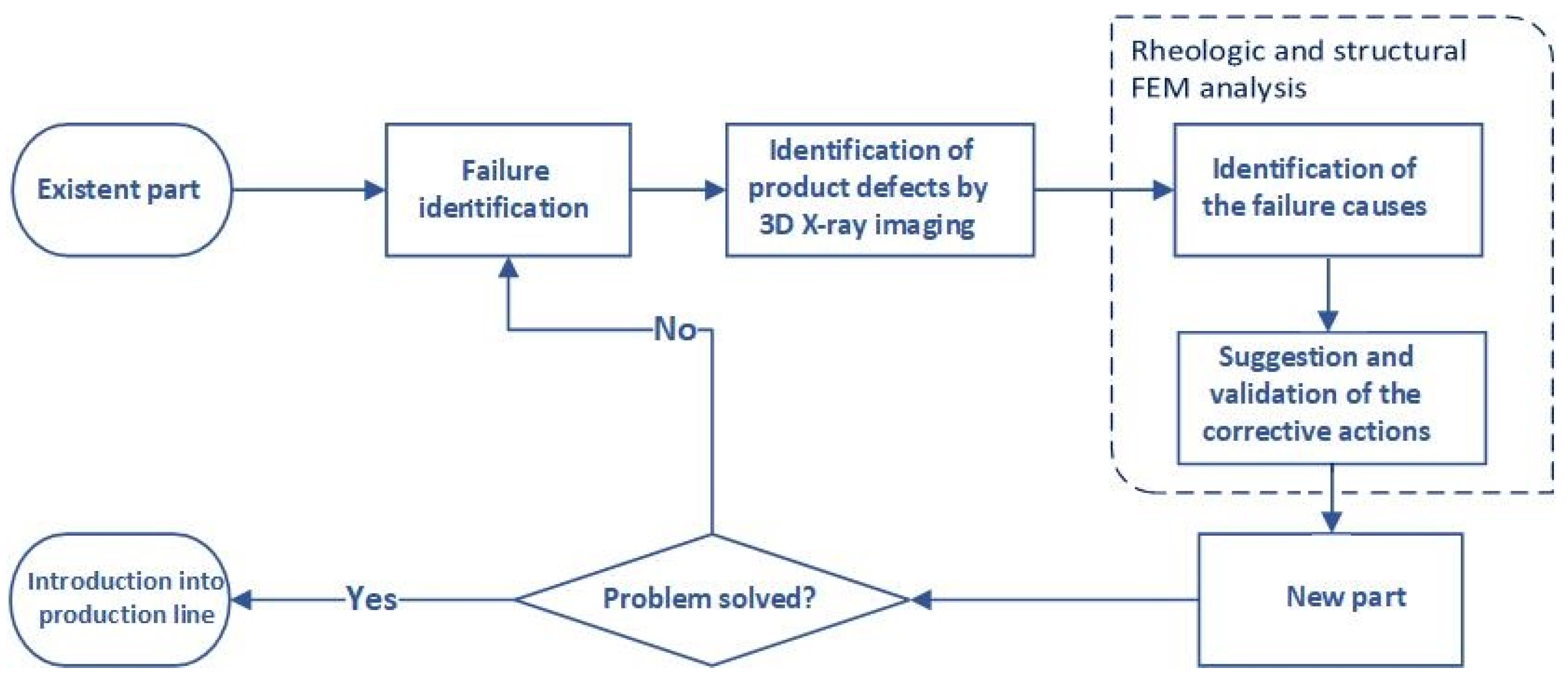
:1. Introduction
- Identification of product defects and their probable causes with the aid of numerical simulation;
- Identification of product defects and their probable causes by 3D X-ray imaging;
- Proposed solutions and their evaluation.
2. Materials and Methods
2.1. Equipment and Materials
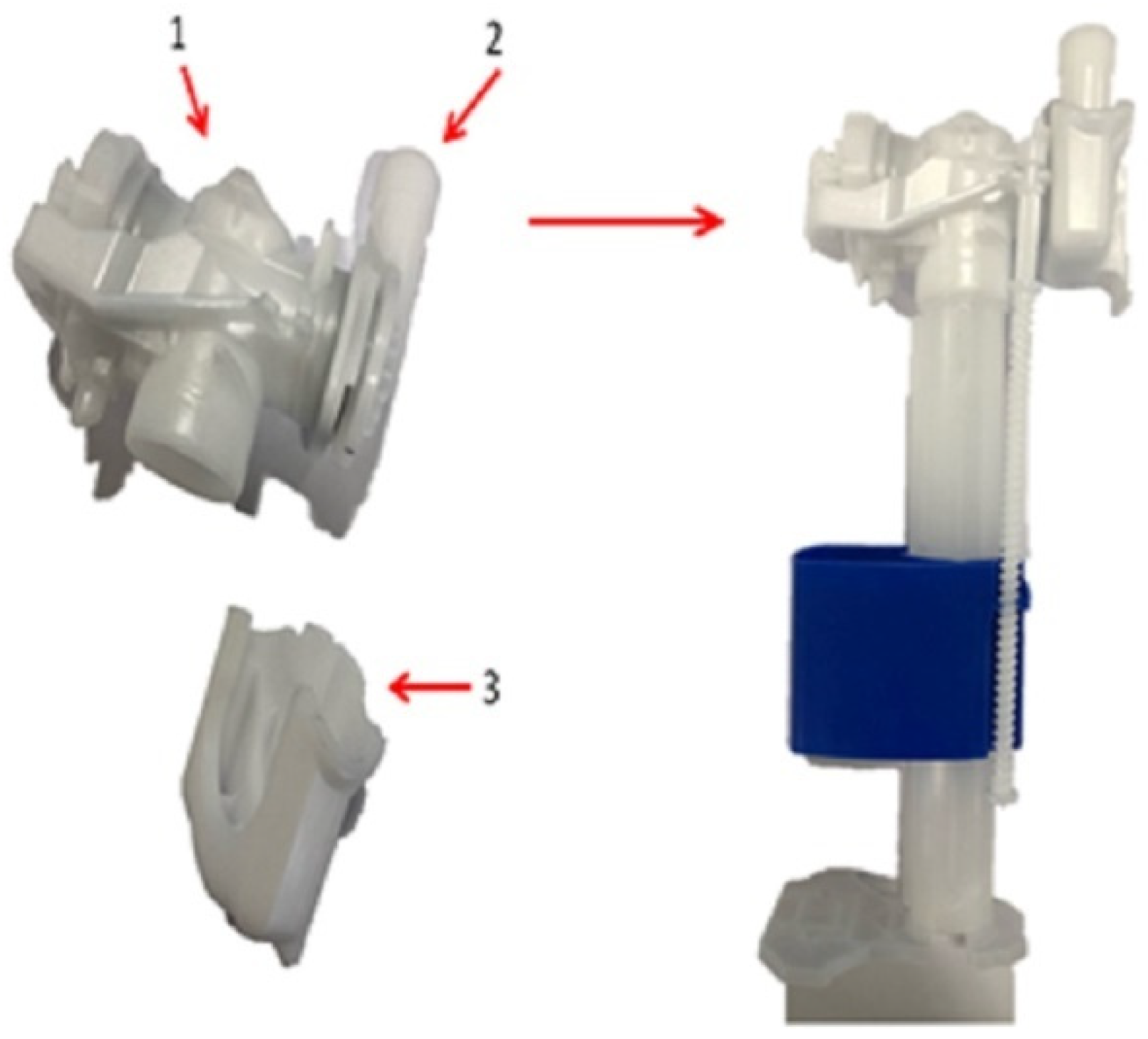
2.1.1. Plastic Part
2.1.2. Plastic Material, Injection Moulding Machine, and Processing Conditions
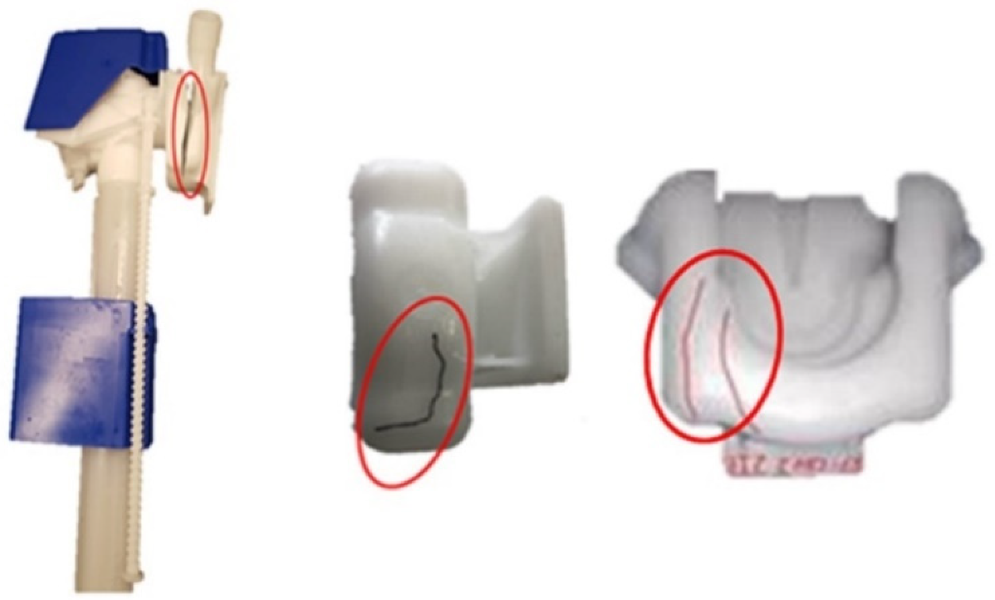
2.1.3. Identification of the Defects
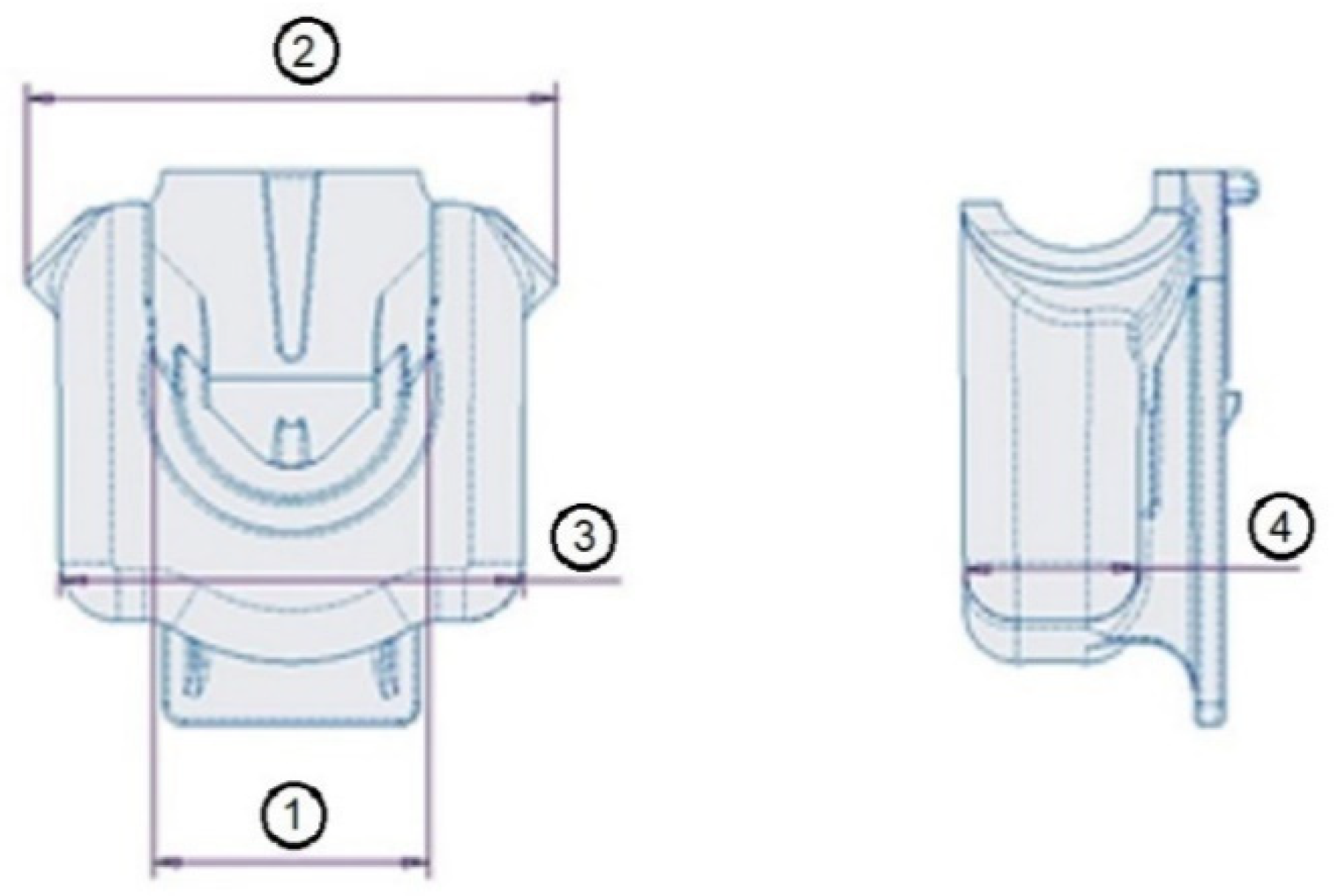
2.1.4. Assessment of the FH Parts Dimensional Tolerances
2.1.5. Microscopy
2.2. Modelling and Simulation of FH Processing and Performance
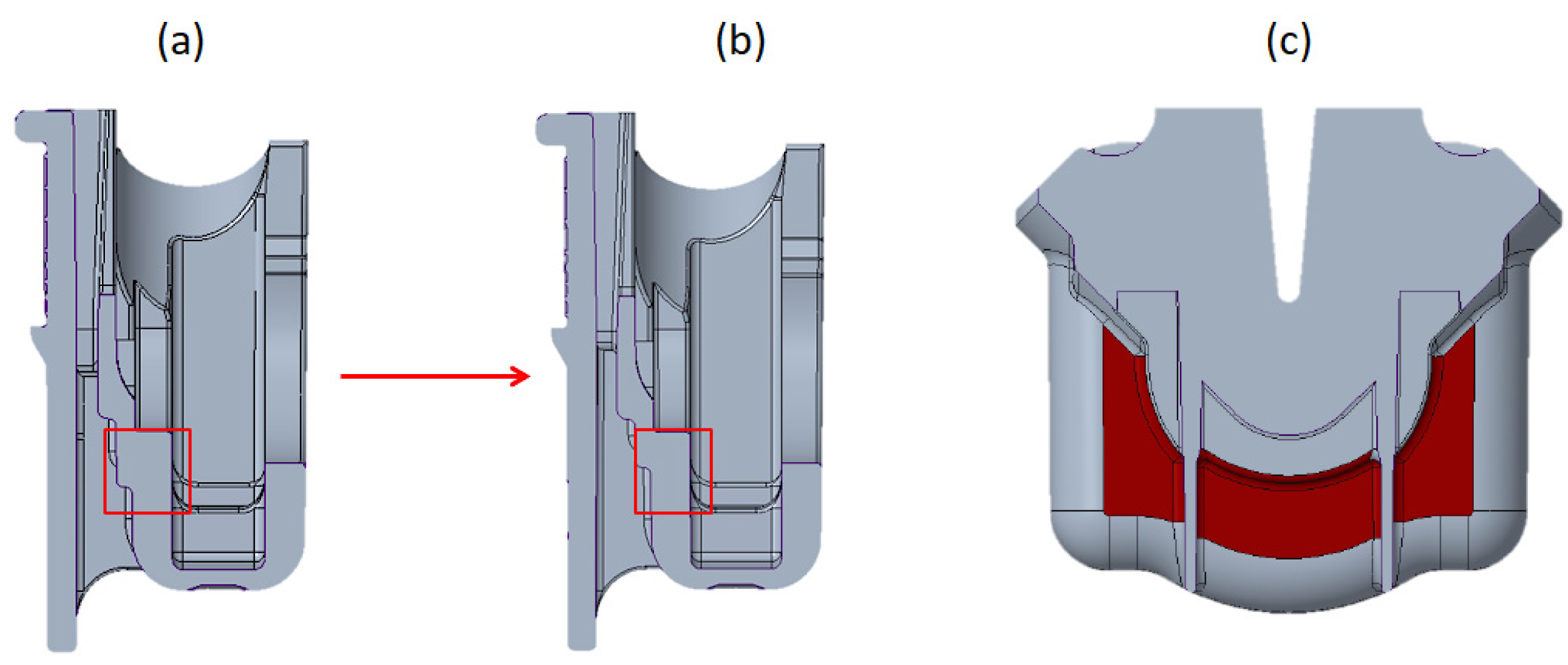
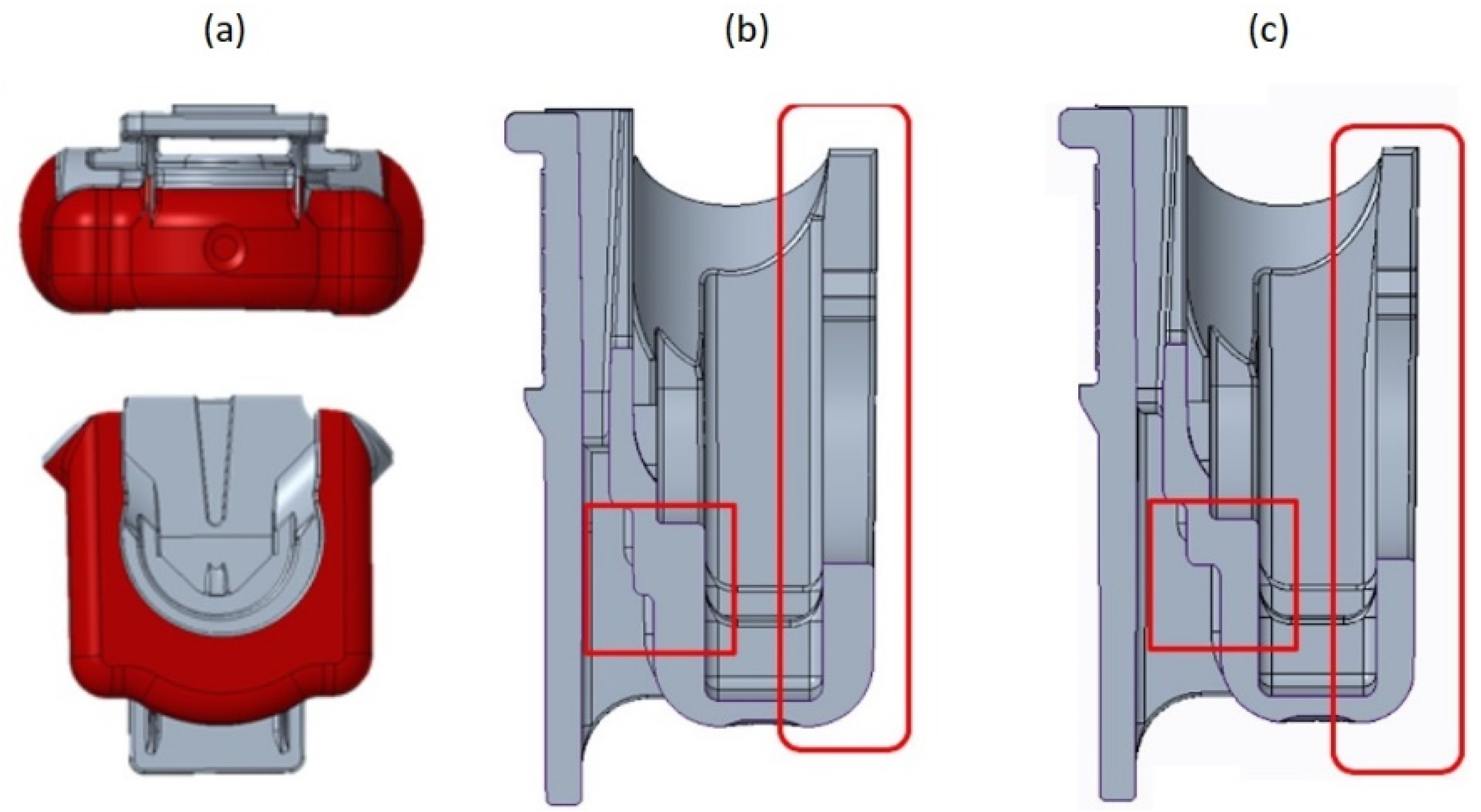
2.2.1. FH Part Redesign
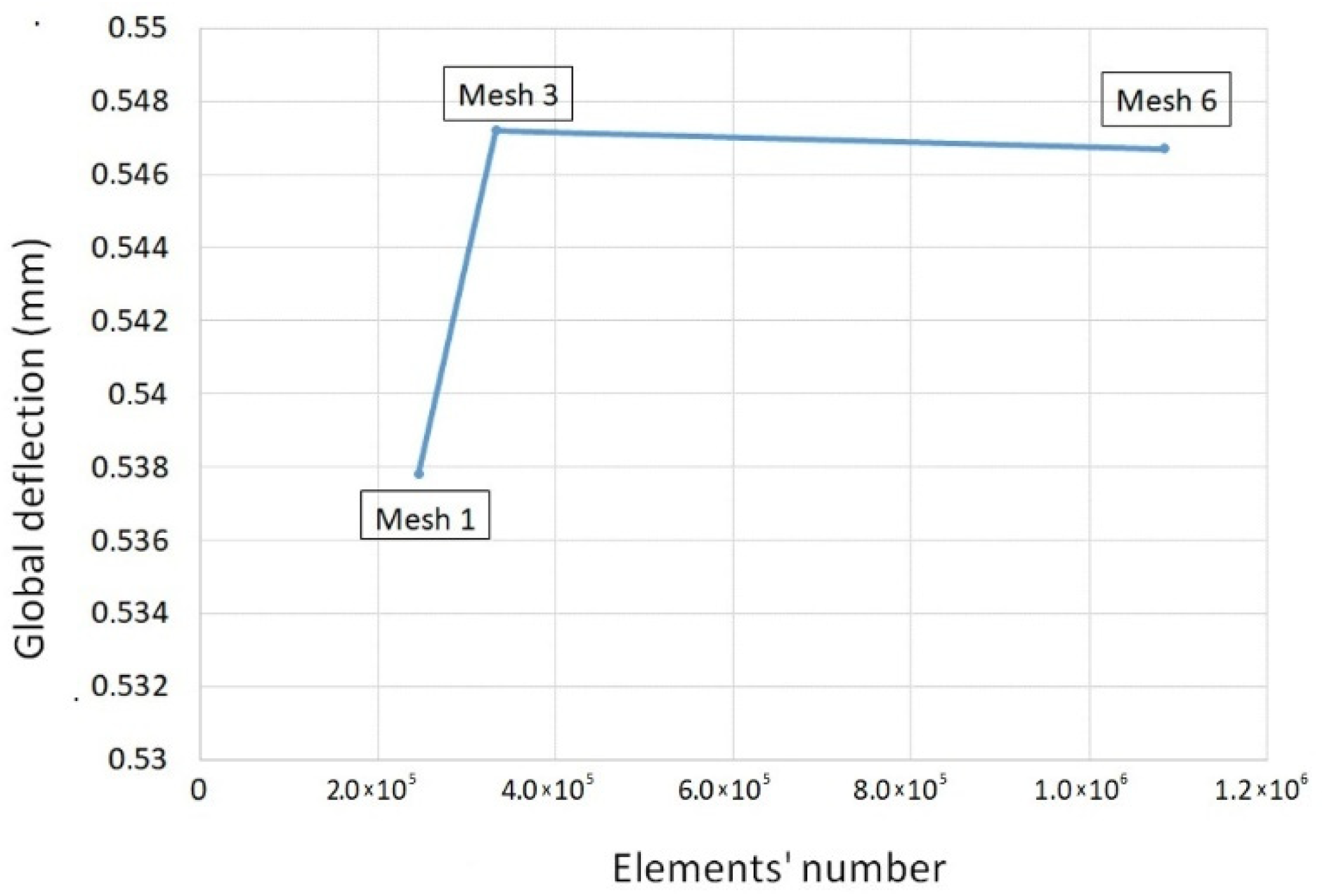
2.2.2. Mesh Independence Study
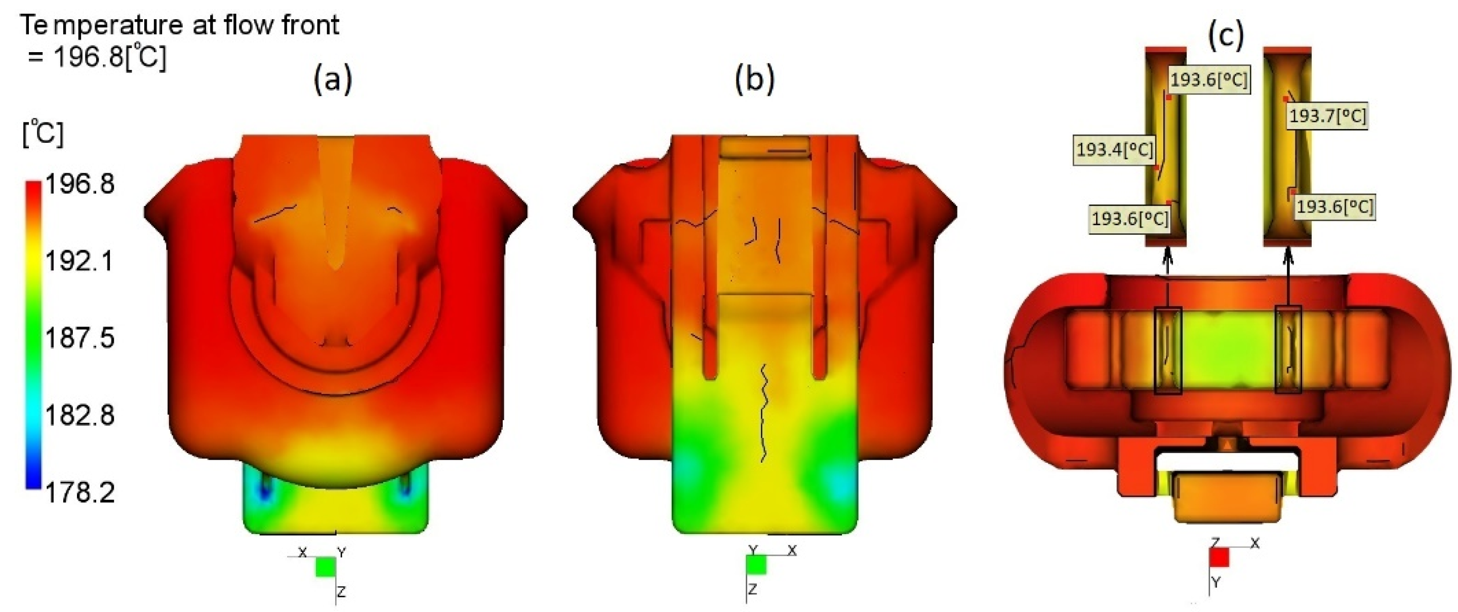
2.2.3. Injection Moulding Simulation of FH Parts
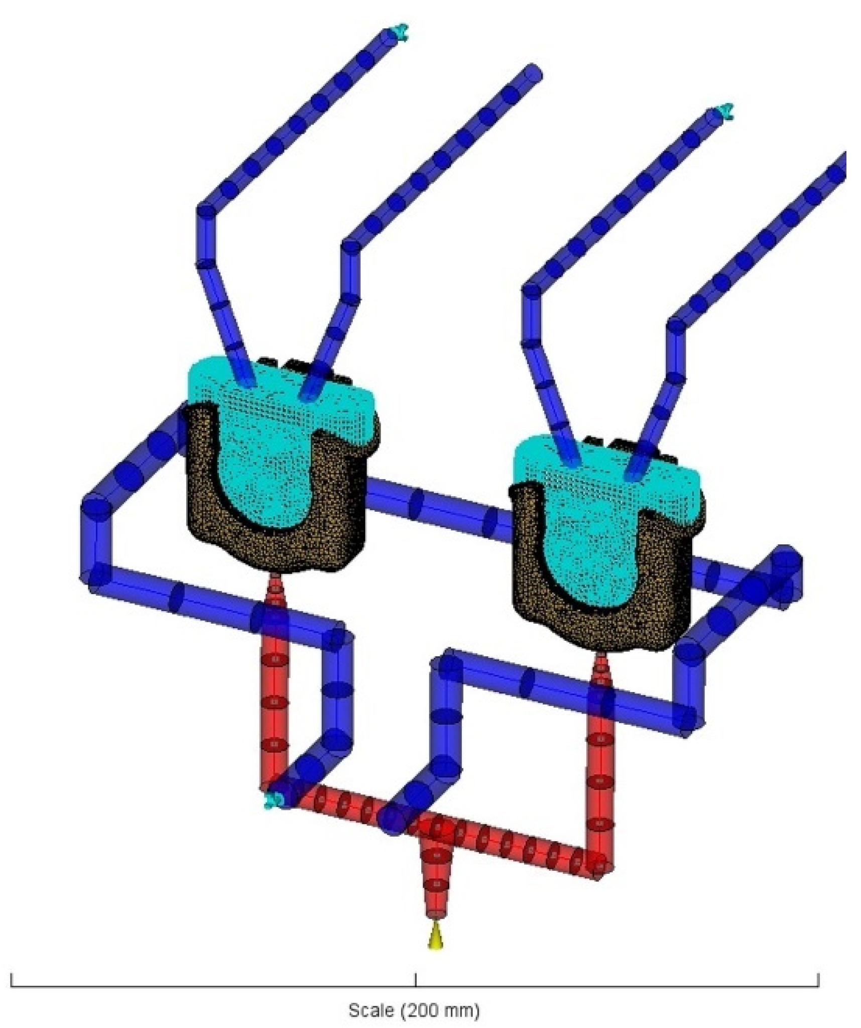
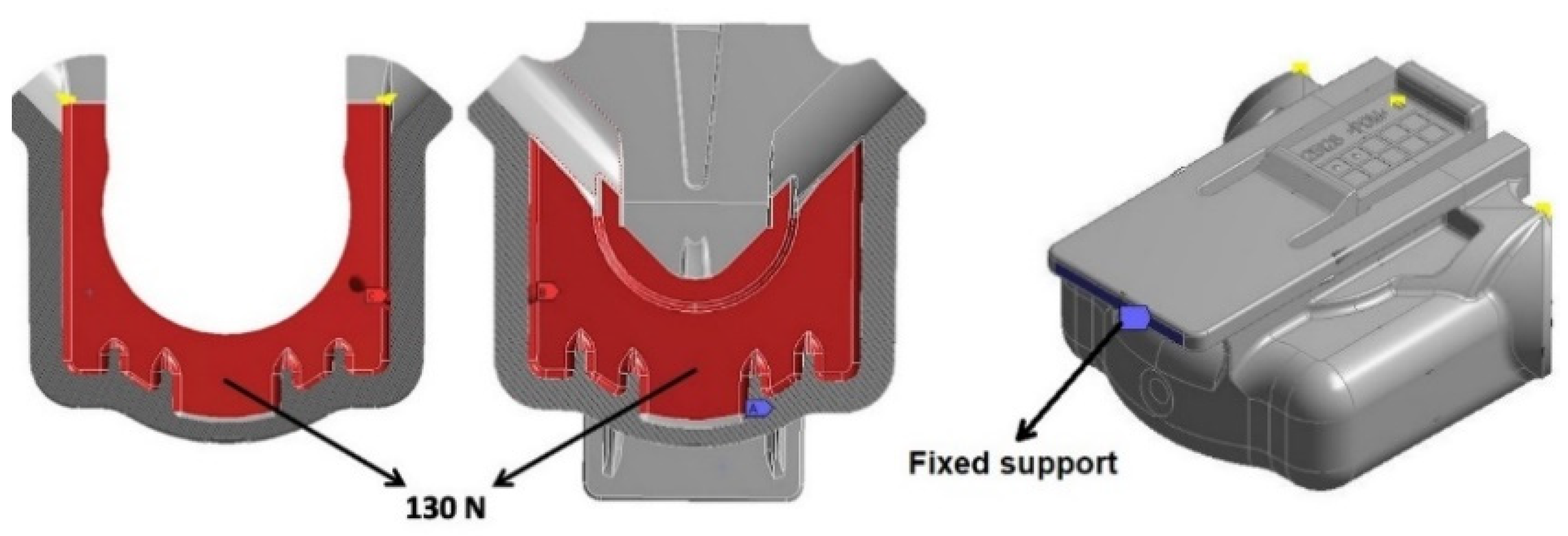
2.2.4. Structural Simulation
3. Results and Discussion
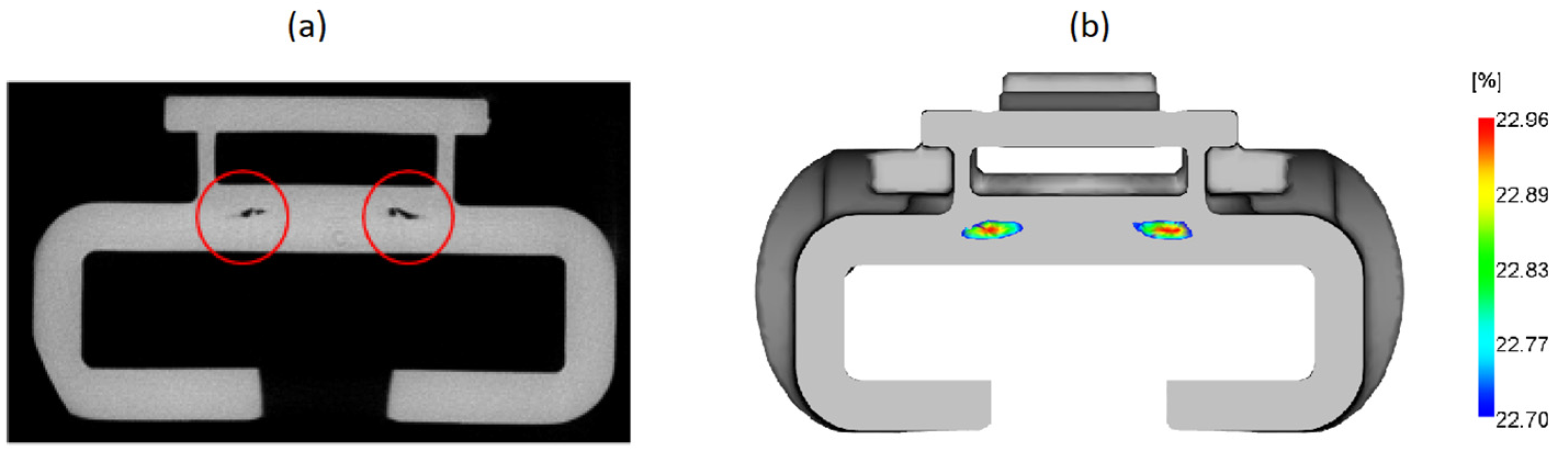
3.1. Diagnostic of the Potential Problems in FH Parts
3.2. Influence of the Redesigns on the Probability of Fracture
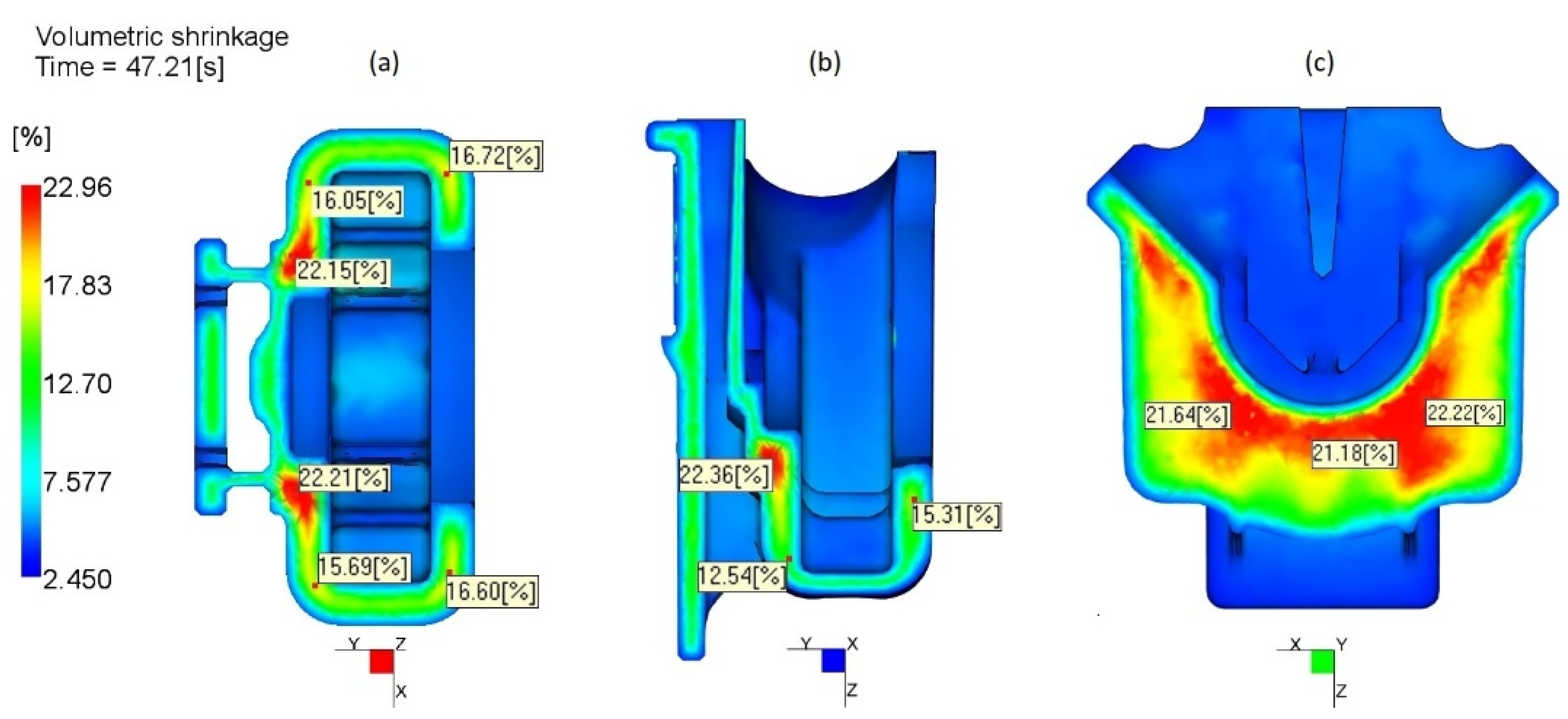
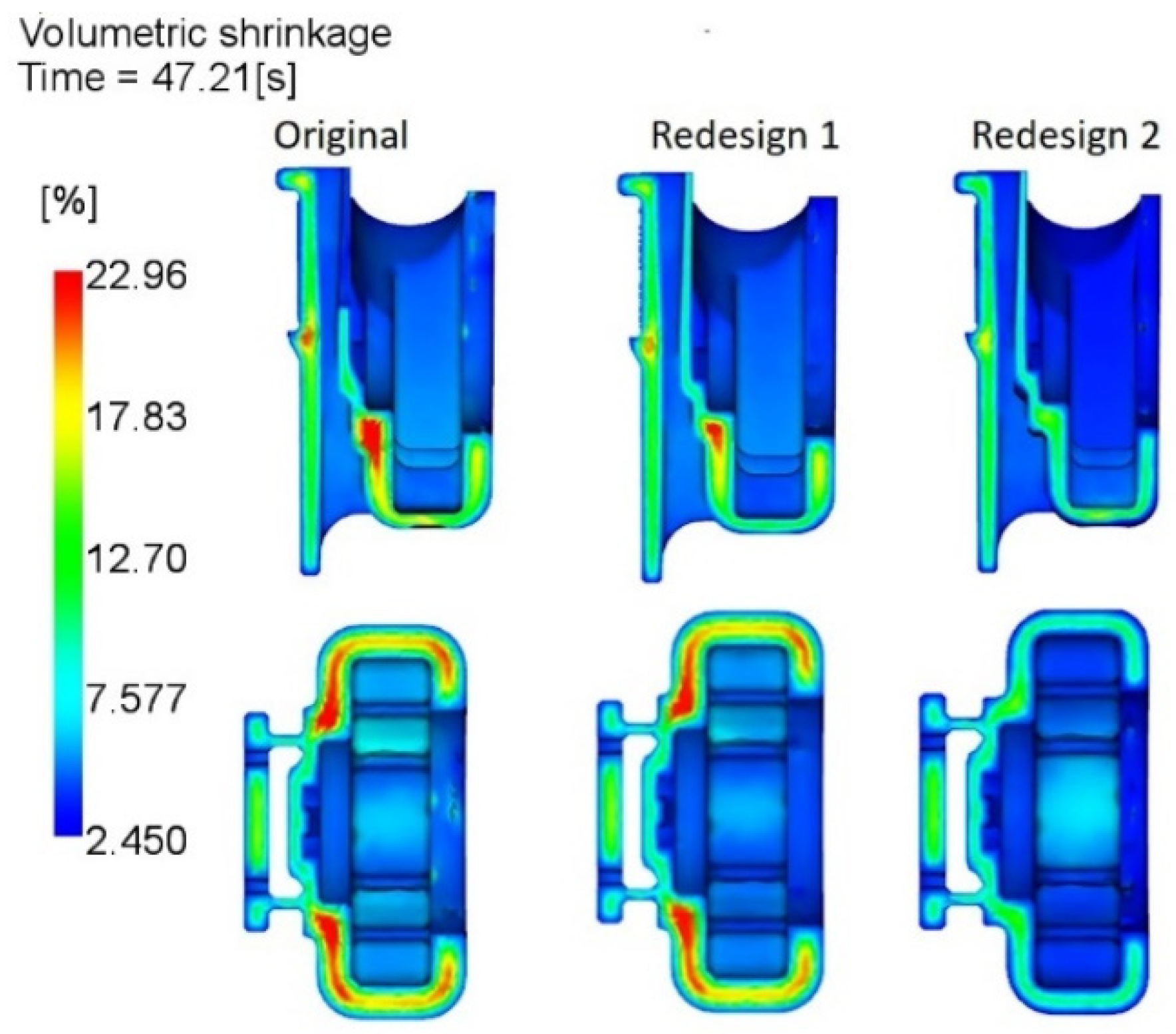
3.2.1. Impact of the Design Modification on Volumetric Shrinkage
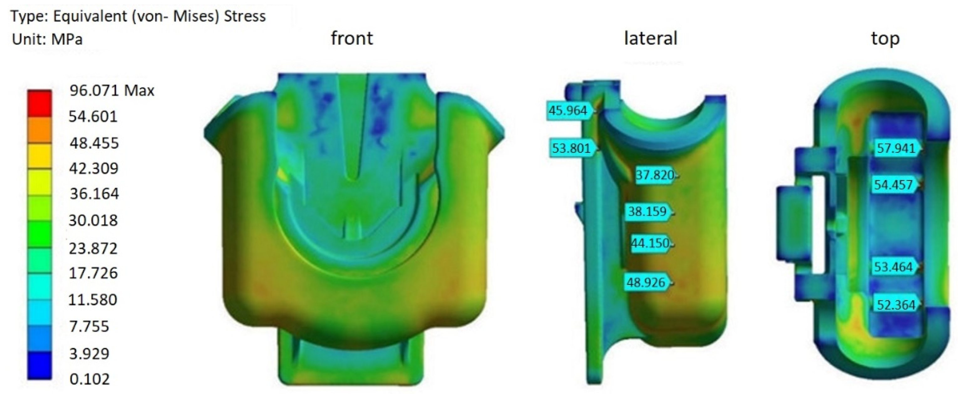
3.2.2. Structural Simulation, without Accounting for Residual Stresses Generated during Processing
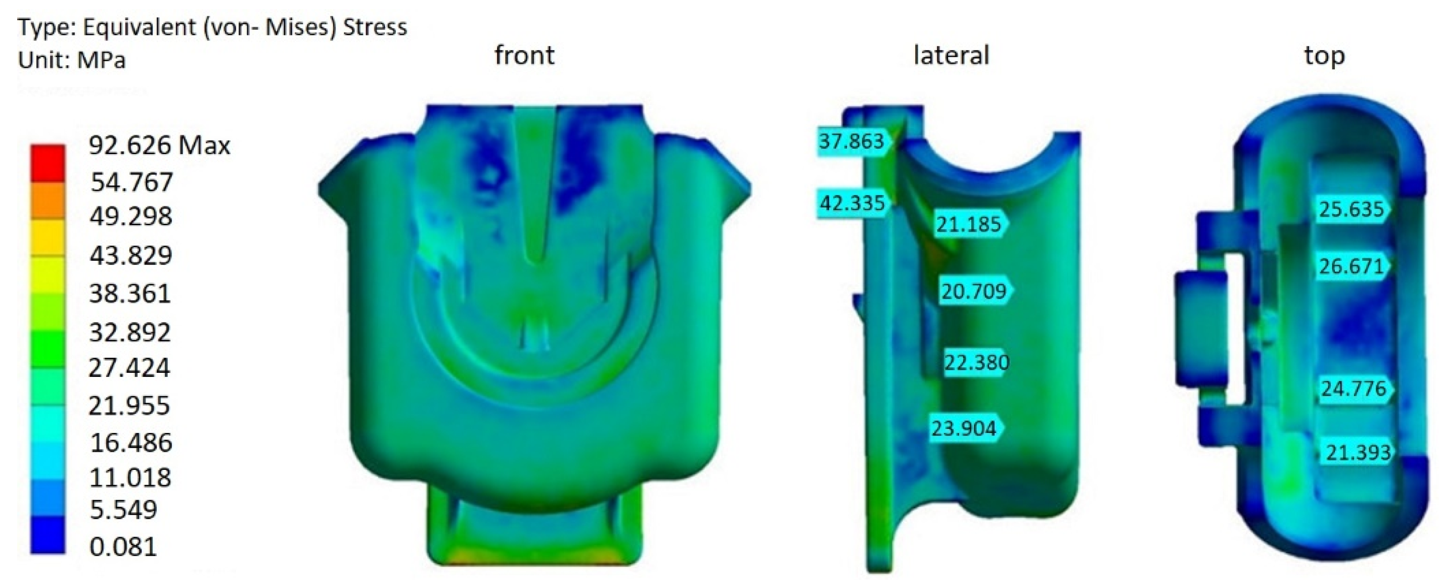
3.2.3. Structural Simulation Accounting for Residual Stresses Generated during Processing
4. Conclusions
Author Contributions
Funding
Institutional Review Board Statement
Informed Consent Statement
Data Availability Statement
Acknowledgments
Conflicts of Interest
References
- MacLean-Blevins, M.T. Designing Successful Products with Plastics: Fundamentals of Plastic Part Design; Elsevier Science: Oxford, UK, 2017. [Google Scholar]
- Torres-Alba, A.; Mercado-Colmenero, J.M.; Caballero-Garcia, J.D.D.; Martin-Doñate, C. Application of New Triple Hook-Shaped Conformal Cooling Channels for Cores and Sliders in Injection Molding to Reduce Residual Stress and Warping in Complex Plastic Optical Parts. Polymers 2021, 13, 2944. [Google Scholar] [CrossRef] [PubMed]
- Hayes, M.; Edwards, D.; Shah, A. Fractography in Failure Analysis of Polymers; Elsevier Science: Oxford, UK, 2015. [Google Scholar]
- Alvarado-Iniesta, A.; Cuate, O.; Schütze, O. Multi-objective and many objective design of plastic injection molding process. Int. J. Adv. Manuf. Technol. 2019, 102, 3165–3180. [Google Scholar] [CrossRef]
- Khosravani, M.R.; Nasiri, S. Injection molding manufacturing process: Review of case-based reasoning applications. J. Intell. Manuf. 2020, 31, 847–864. [Google Scholar] [CrossRef]
- Jin, K.; Jeong, T.; Kim, T.; Kim, N.; Kim, B. Analysis and design for reducing residual stress and distortion after ejection of injection molded part with metal-insert. Int. J. Precis. Eng. Manuf. 2014, 15, 2533–2542. [Google Scholar] [CrossRef]
- Yasin, S.B.M.; Mohd, N.F.; Mahmud, J.; Whashilah, N.S.; Razak, Z. A reduction of protector cover warpage via topology optimization. Int. J. Adv. Manuf. Technol. 2018, 98, 2531–2537. [Google Scholar] [CrossRef]
- Roslan, N.; Abd Rahim, S.Z.; Abdellah, A.E.H.; Abdullah, M.M.A.B.; Błoch, K.; Pietrusiewicz, P.; Nabiałek, M.; Szmidla, J.; Kwiatkowski, D.; Correia Vasco, J.O.; et al. Optimisation of Shrinkage and Strength on Thick Plate Part Using Recycled LDPE Materials. Materials 2021, 14, 1795. [Google Scholar] [CrossRef] [PubMed]
- Bai, L.; Zhang, H.Y.; Liu, W. Influence of injection molding process parameters on sink marks of injection parts based on Moldflow. Appl. Mech. Mater. 2013, 347, 1163–1167. [Google Scholar] [CrossRef]
- Rosato, D.V.; Di Mattia, P. Designing with Plastics and Composites: A Handbook; Springer: New York, NY, USA, 2013. [Google Scholar]
- Sanchez-Caballero, S.; Selles, M.A.; Ferrandiz, S.; Peydro, M.A.; Oliver, B.A. Failure analysis of a plastic modular belt in-service. Eng. Fail. Anal. 2018, 93, 13–25. [Google Scholar] [CrossRef]
- Francis, D.K.; Deang, J.; Florea, R.S.; Gaston, D.R.; Lee, N.; Nouranian, S.; Permann, C.J.; Rudd, J.; Seely, D.; Whittington, W.R.; et al. Characterization and failure analysis of a polymeric clamp hanger component. Eng. Fail. Anal. 2012, 26, 230–239. [Google Scholar] [CrossRef]
- Kleindel, S.; Salaberger, D.; Eder, R.; Schretter, H.; Hochenauer, C. Measurement and Numerical Simulation of Void and Warpage in Glass Fiber Reinforced Molded Chunky Parts. Int. Polym. Process. 2015, 30, 100–112. [Google Scholar] [CrossRef]
- Vaxman, A.; Narkis, M.; Siegmann, A.; Kenig, S. Void formation in short-fiber thermoplastic composites. Polym. Compos. 1989, 10, 449–453. [Google Scholar] [CrossRef]
- International Plastics Database CAMPUS. Datasheet of HOSTAFORM® C 27021 from Celanese. Available online: https://www.campusplastics.com/campus/en/datasheet/HOSTAFORM®+C+27021/Celanese/163/b5554489 (accessed on 11 May 2021).
- Brinson, H.F.; Brinson, L.C. Polymer Engineering Science and Viscoelasticity: An Introduction; Springer: New York, NY, USA, 2008. [Google Scholar]
- Autodesk Knowledge Network. Helius PFA 2019. Available online: https://help.autodesk.com/view/ACMPAN/2019/ENU/?guid=GUID-63DBAFC6-05FD-4827-BED3-F5C93A759234 (accessed on 13 May 2021).
- Autodesk Moldflow Insight 2019. Volumetric Shrinkage Result. Available online: https://help.autodesk.com/view/MFIA/2019/ENU/?guid=GUID-5980B07E-A80A-4A35-901E-76E56959F6A6 (accessed on 15 May 2021).
- Filho, A.; Atolino, W. Mitigating the cost of automotive injected parts or Advances on injection molding of semi-crystalline engineering plastics. In Proceedings of the SAE Brasil Congress and Exhibit 2008, São Paulo, Brazil, 7–9 October 2008. [Google Scholar]
- Kleindel, S.; Eder, R.; Schretter, H.; Hochenauer, C. Experimental and Numerical Investigation of Shrinkage and Warpage of a U-Shaped Injection Molded Part. Int. Polym. Process. 2016, 31, 68–81. [Google Scholar] [CrossRef]
- Geyer, A.; Bonten, C. Enhancing the weld line strength of injection molded components. In AIP Conference Proceedings; AIP Publishing: College Park, MD, USA, 2019; Volume 2055. [Google Scholar]
- Navidi, W. Principles of Statistics for Engineers and Scientists; McGraw-Hill Higher Education: Columbus, OH, USA, 2010. [Google Scholar]
- Mohan, M.; Ansari, M.N.M.; Shanks, R.A. Review on the Effects of Process Parameters on Strength, Shrinkage, and Warpage of Injection Molding Plastic Component. Polym. Plast. Technol. Eng. 2017, 56, 1–12. [Google Scholar] [CrossRef]
- Margolis, J.M. Engineering Thermoplastics: Properties and Applications; CRC Press: New York, NY, USA, 2020. [Google Scholar]
- Autodesk Moldflow Insight 2019. 3D Residual Stress Model. Available online: https://help.autodesk.com/view/MFIA/2019/ENU/?guid=GUID-0B462903-CBB5-42D2-8DD8-7BB93551159C (accessed on 2 October 2021).
- Kim, C.H.; Youn, J.R. Determination of residual stresses in injection-moulded flat plate: Simulation and experiments. Polym. Test. 2007, 26, 862–868. [Google Scholar] [CrossRef]
- Kabanemi, K.K.; Vaillancourt, H.; Wang, H.; Salloum, G. Residual stresses, shrinkage, and warpage of complex injection molded products: Numerical simulation and experimental validation. Polym. Eng. Sci. 1998, 38, 21–37. [Google Scholar] [CrossRef]
- Saint-Martin, G.; Schmidt, F.; Devos, P.; Levaillant, C. Voids in short fibre-reinforced injection-moulded parts: Density control vs. mass control. Polym. Test. 2003, 22, 947–953. [Google Scholar] [CrossRef] [Green Version]
- He, X.; Wu, W. A Practical Numerical Approach to Characterizing Non-Linear Shrinkage and Optimizing Dimensional Deviation of Injection-Molded Small Module Plastic Gears. Polymers 2021, 13, 2092. [Google Scholar] [CrossRef] [PubMed]
- Thornburg, H. Overview of the PETTT Workshop on Mesh Quality/Resolution, Practice, Current Research, and Future Directions. In Proceedings of the 50th AIAA Aerospace Sciences Meeting including the New Horizons Forum and Aerospace Exposition, Nashville, TN, USA, 9–12 January 2012. [Google Scholar]
- ANSYS, Inc. ANSYS Meshing User’s Guide; ANSYS, Inc.: Southpointe, PA, USA, 2018. [Google Scholar]


| Processing Condition | Value |
|---|---|
| Melt temperature (°C) | 190 |
| Cooling water temperature (°C) | 80 |
| Injection time (s) | 1.6 |
| Packing time (s) | 16 |
| Packing pressure (MPa) | 28 |
| Cooling time (s) | 27 |
| Density Ρ (kg/m3) | Coefficient of Thermal Expansion A (10−6/K) | Young’s Modulus E (MPa) | Poisson Coefficient ν | Bulk Modulus K * (MPa) | Shear Modulus G * (MPa) | Yield Stress (MPa) | Tensile Strength (Mpa) |
|---|---|---|---|---|---|---|---|
| 1410 | 110 | 2900 | 0.4 | 4833 | 1036 | 65 | 55 |
| Mesh nº | Global Edge Length | Max. Aspect Ratio | Elements’ Number |
|---|---|---|---|
| 1 | 1.5 | 59 | 245,650 |
| 2 | 1.3 | 64 | 299,727 |
| 3 | 1.2 | 55 | 332,678 |
| 4 | 1.0 | 58 | 441,818 |
| 5 | 0.8 | 65 | 611,380 |
| 6 | 0.5 | 49 | 1,083,970 |
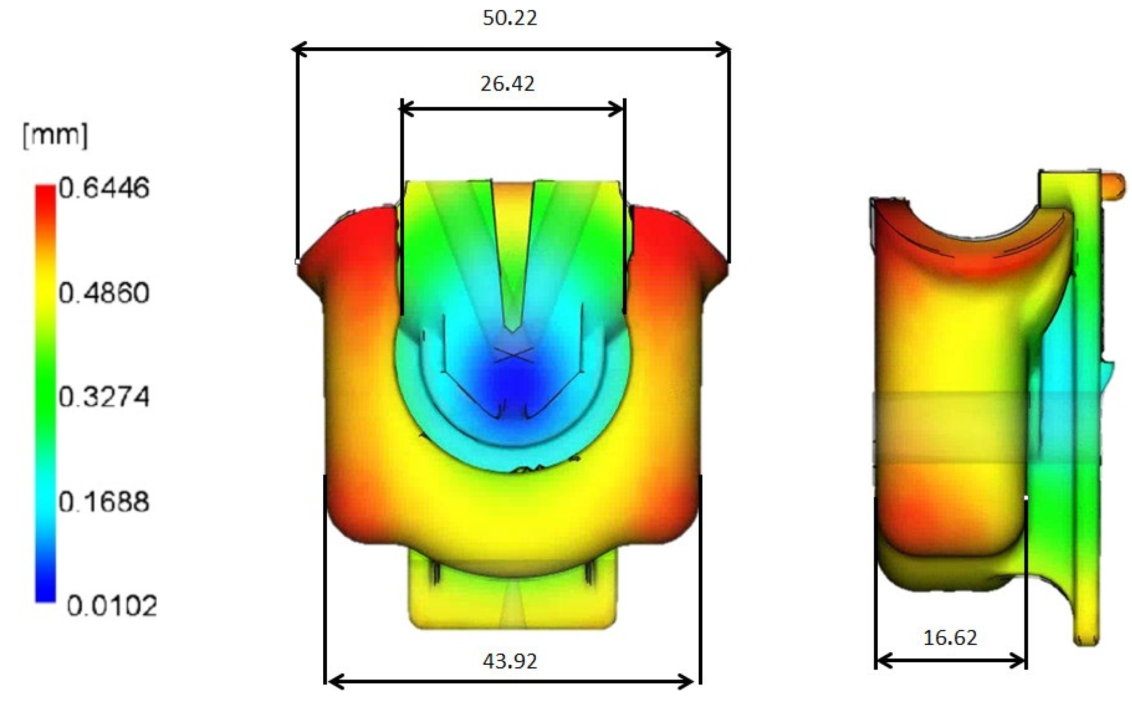
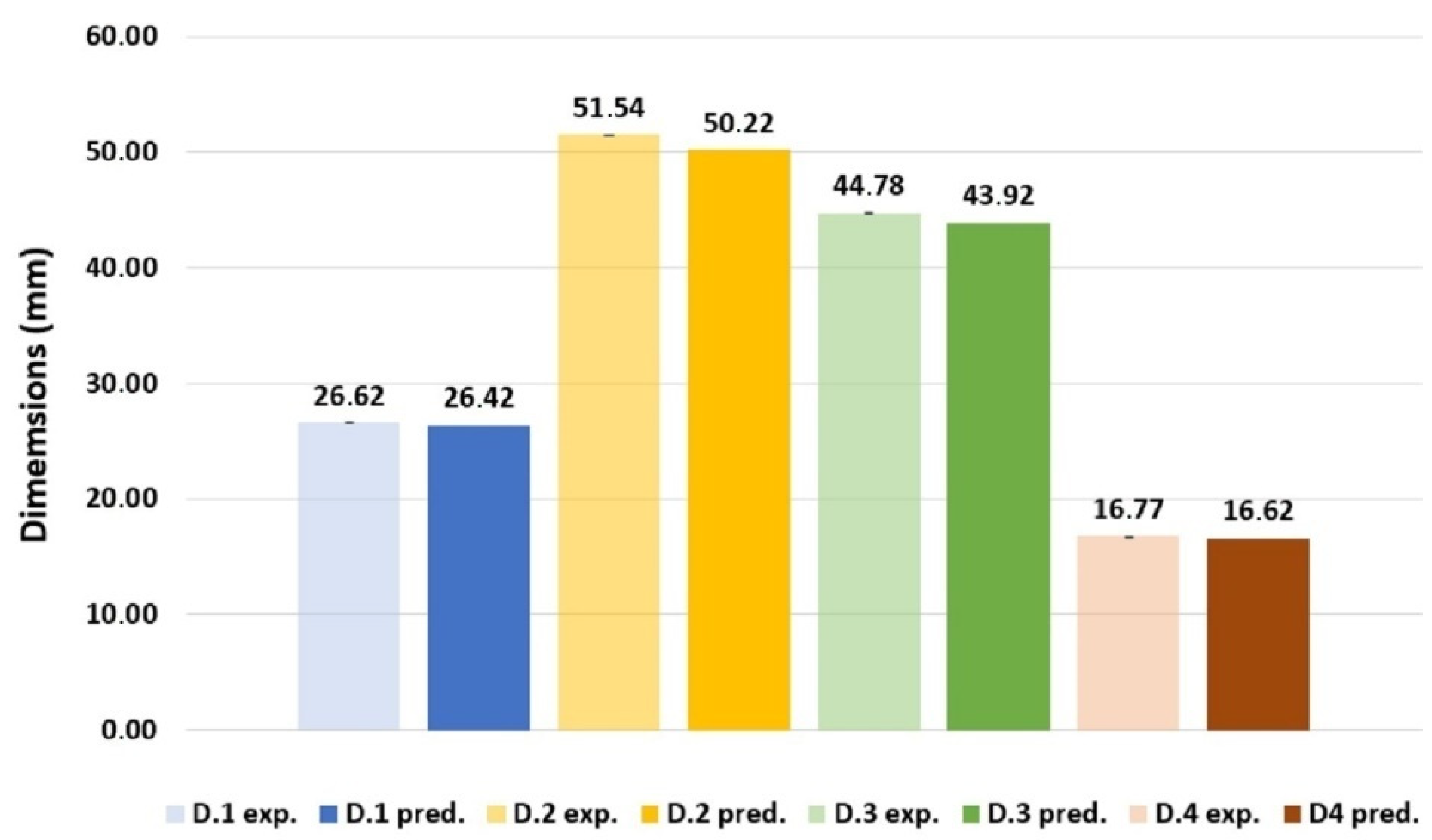
| D.1 (mm) | D.2 (mm) | D.3 (mm) | D.4 (mm) | |
|---|---|---|---|---|
| Predicted by AMI | 26.42 | 50.22 | 43.92 | 16.62 |
| Experimental average | 26.62 | 51.54 | 44.78 | 16.77 |
| Standard Deviation | 0.0214 | 0.0295 | 0.0168 | 0.0207 |
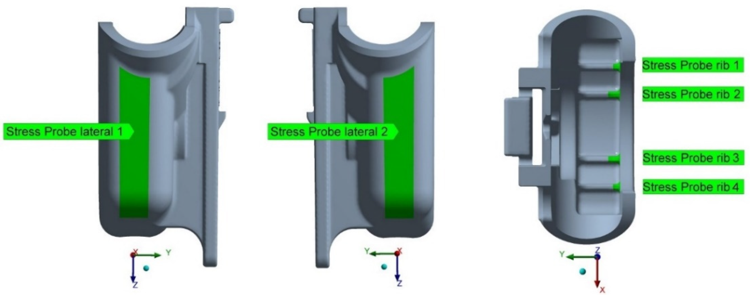
| Stress Probe Locations | σor. (MPa) | σr1 (MPa) | σr2 (MPa) | Δσvr11 % | Δσvr22 % |
|---|---|---|---|---|---|
| Lateral 1 | 1.62 | 1.61 | 2.15 | 0.62 | 33.54 |
| Lateral 2 | 1.60 | 1.62 | 2.09 | 1.25 | 29.01 |
| Rib 1 | 6.08 | 6.15 | 8.46 | 1.15 | 37.56 |
| Rib 2 | 8.03 | 8.11 | 10.90 | 1.00 | 34.40 |
| Rib 3 | 8.07 | 8.11 | 10.89 | 0.50 | 34.28 |
| Rib 4 | 6.44 | 6.58 | 8.42 | 2.17 | 27.96 |
| Stress Probe Locations | σor. (MPa) | σor.p.h.1 (MPa) | σr.2 (MPa) | σr.2p.h.2 % | Δσp.h. % |
|---|---|---|---|---|---|
| Lateral 1 | 1.62 | 52.61 | 2.15 | 27.79 | 47 |
| Lateral 2 | 1.60 | 50.1 | 2.09 | 28.14 | 44 |
| Rib 1 | 6.08 | 61.83 | 8.46 | 32.73 | 47 |
| Rib 2 | 8.03 | 57.71 | 10.90 | 28.17 | 51 |
| Rib 3 | 8.07 | 60.34 | 10.89 | 27.87 | 54 |
| Rib 4 | 6.44 | 60.63 | 8.42 | 28.61 | 53 |
Publisher’s Note: MDPI stays neutral with regard to jurisdictional claims in published maps and institutional affiliations. |
© 2021 by the authors. Licensee MDPI, Basel, Switzerland. This article is an open access article distributed under the terms and conditions of the Creative Commons Attribution (CC BY) license (https://creativecommons.org/licenses/by/4.0/).
Share and Cite
Pinho, T.; Zhiltsova, T.; Oliveira, M.; Costa, A. Computer-Aided Reengineering towards Plastic Part Failure Minimization. Materials 2021, 14, 6303. https://doi.org/10.3390/ma14216303
Pinho T, Zhiltsova T, Oliveira M, Costa A. Computer-Aided Reengineering towards Plastic Part Failure Minimization. Materials. 2021; 14(21):6303. https://doi.org/10.3390/ma14216303
Chicago/Turabian StylePinho, Tiago, Tatiana Zhiltsova, Mónica Oliveira, and Andreia Costa. 2021. "Computer-Aided Reengineering towards Plastic Part Failure Minimization" Materials 14, no. 21: 6303. https://doi.org/10.3390/ma14216303
APA StylePinho, T., Zhiltsova, T., Oliveira, M., & Costa, A. (2021). Computer-Aided Reengineering towards Plastic Part Failure Minimization. Materials, 14(21), 6303. https://doi.org/10.3390/ma14216303