
Carbon Electrodes in Perovskite Photovoltaics


Abstract
:
1. Introduction
2. Features of Carbon Electrodes in Perovskite Photovoltaics
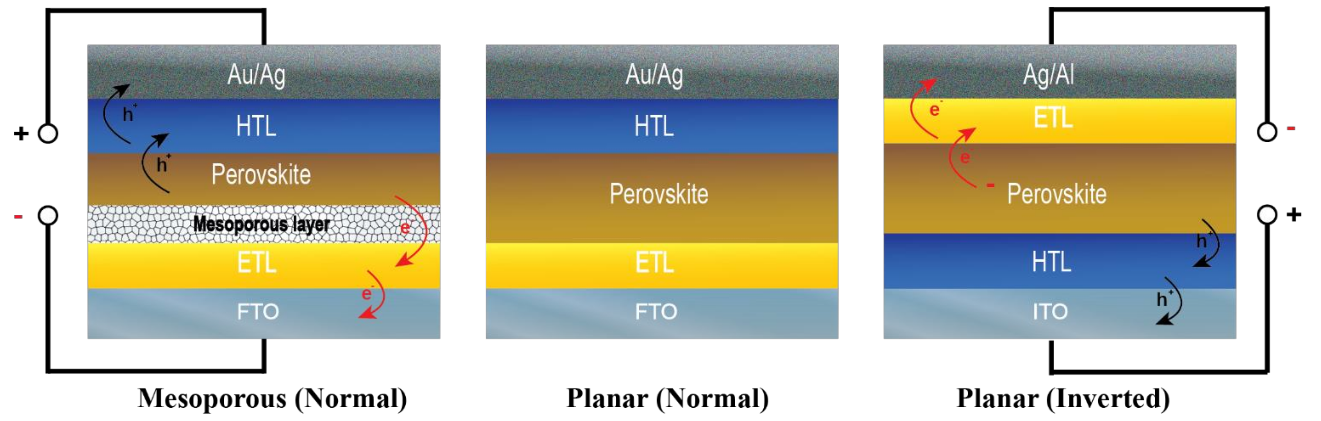
2.1. Structure of Carbon Electrode-Based Perovskite Photovoltaics
2.2. Benefits of Carbon Electrodes in Perovskite Photovoltaics
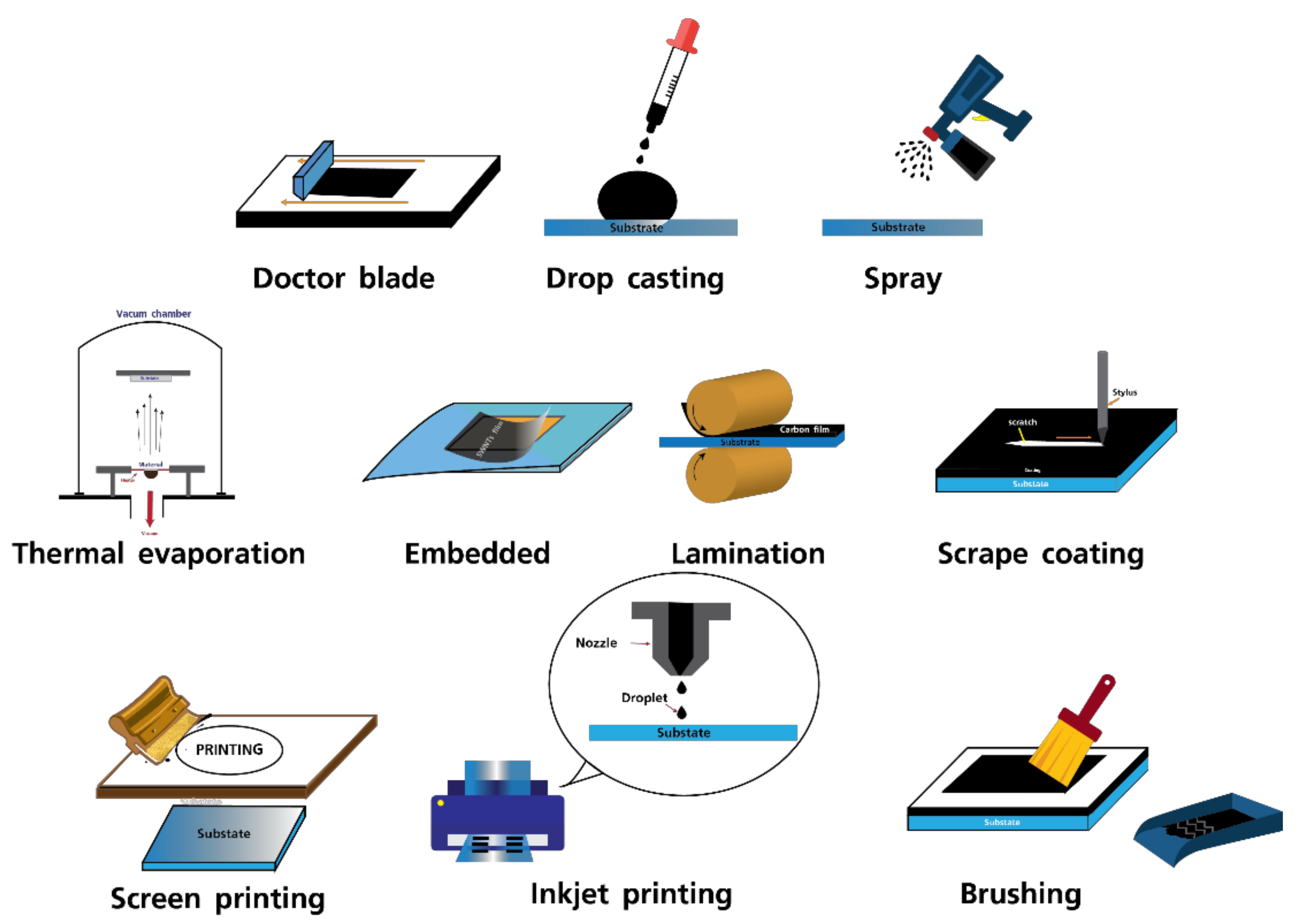
3. Fabrication Methods for Carbon Electrodes in Perovskite Photovoltaics and Their Performances
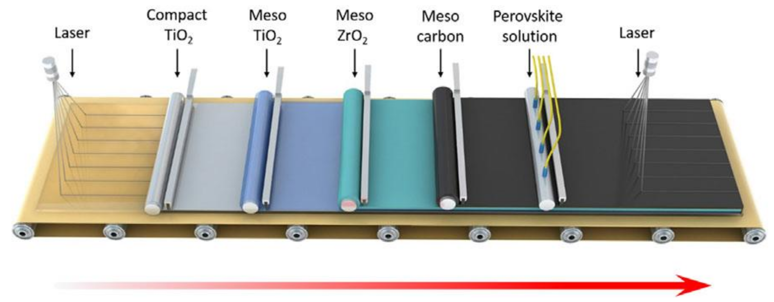
4. Substrates, Stabilities, and Performances of Large-Area Perovskite Photovoltaics Made of Carbon Electrodes
5. Conclusions and Outlook
Author Contributions
Funding
Institutional Review Board Statement
Informed Consent Statement
Data Availability Statement
Acknowledgments
Conflicts of Interest
References
- Loi, M.A.; Hummelen, J.C. Perovskites under the Sun. Nat. Mater. 2013, 12, 1087–1089. [Google Scholar] [PubMed]
- Saliba, M.; Matsui, T.; Seo, J.Y.; Domanski, K.; Correa-Baena, J.P.; Nazeeruddin, M.K.; Zakeeruddin, S.M.; Tress, W.; Abate, A.; Hagfeldtd, A.; et al. Cesium-containing triple cation perovskite solar cells: Improved stability, reproducibility and high efficiency. Energy Environ. Sci. 2016, 9, 1989–1997. [Google Scholar] [CrossRef] [PubMed] [Green Version]
- Wehrenfennig, C.; Eperon, G.E.; Johnston, M.B.; Snaith, H.J.; Herz, L.M. High charge carrier mobilities and lifetimes in organolead trihalide perovskites. Adv. Mater. 2014, 26, 1584–1589. [Google Scholar] [CrossRef] [PubMed] [Green Version]
- Kojima, A.; Teshima, K.; Shirai, Y.; Miyasaka, T. Organometal halide perovskites as visible-light sensitizers for photovoltaic cells. J. Am. Chem. Soc. 2009, 131, 6050–6051. [Google Scholar] [CrossRef] [PubMed]
- Snaith, H.J. Perovskites: The emergence of a new era for low-cost, high-efficiency solar cells. J. Phys. Chem. Lett. 2013, 4, 3623–3630. [Google Scholar] [CrossRef]
- National Renewable Energy Laboratory (NREL). Available online: https://www.nrel.gov/pv/assets/pdfs/best-research-cell-efficiencies.20200104.pdf (accessed on 31 March 2021).
- Azmi, R.; Hwang, S.; Yin, W.; Kim, T.W.; Ahn, T.K.; Jang, S.Y. High efficiency low-temperature processed perovskite solar cells integrated with alkali metal doped ZnO electron transport layers. ACS Energy Lett. 2018, 3, 1241–1246. [Google Scholar] [CrossRef]
- Su, H.; Xiao, J.; Li, Q.; Peng, C.; Zhang, X.; Mao, C.; Yao, Q.; Lu, Y.; Ku, Z.; Zhong, J.; et al. Carbon film electrode based square-centimeter scale planar perovskite solar cells exceeding 17% efficiency. Mater. Sci. Semicond. Process. 2020, 107, 104809. [Google Scholar] [CrossRef]
- Bai, S.H.; Cheng, N.A.; Yu, Z.H.; Liu, P.; Wang, C.L.; Zhao, X.Z. Cubic: Column composite structure (NH2CH=NH2)x(CH3NH3)1-xPbI3 for efficient hole-transport material-free and insulation. Electrochim. Acta 2016, 190, 775–779. [Google Scholar] [CrossRef]
- Zhao, Q.; Wu, R.; Zhang, Z.; Xiong, J.; He, Z.; Fan, B.; Dai, Z.; Yang, B.; Xue, X.; Cai, P.; et al. Achieving efficient inverted planar perovskite solar cells with nondoped PTAA as a hole transport layer. Org. Electron. 2019, 71, 106–112. [Google Scholar] [CrossRef]
- Yang, Y.; Hoang, M.T.; Yao, D.; Pham, N.D.; Tiong, V.T.; Wang, X.; Wang, H. Spiro-OMeTAD or CuSCN as a preferable hole transport material for carbon-based planar perovskite solar cells. J. Mater. Chem. A 2020, 8, 12723–12734. [Google Scholar] [CrossRef]
- Lee, D.S.; Kim, W.; Cha, B.G.; Kwon, J.; Kim, S.J.; Kim, M.; Kim, J.; Wang, D.H.; Park, J.H. Self-position of Au NPs in perovskite solar cells: Optical and electrical contribution. ACS Appl. Mater. Interfaces 2016, 8, 449–454. [Google Scholar] [CrossRef]
- Frackowiak, E. Carbon materials for supercapacitor application. Phys. Chem. Chem. Phys. 2007, 9, 1774–1785. [Google Scholar] [CrossRef] [PubMed]
- Kalita, G.; Adhikari, S.; Aryal, H.R.; Afre, R.; Soga, T.; Sharon, M.; Umeno, M. Functionalization of multi-walled carbon nanotubes (MWCNTs) with nitrogen plasma for photovoltaic device application. Curr. Appl. Phys. 2009, 9, 346–351. [Google Scholar] [CrossRef]
- Raoof, J.B.; Ojani, R.; Baghayeri, M.; Amiri-Aref, M. Application of a glassy carbon electrode modified with functionalized multi-walled carbon nanotubes as a sensor device for simultaneous determination of acetaminophen and tyramine. Anal. Methods 2012, 4, 1579–1587. [Google Scholar] [CrossRef]
- Phillips, C.; Al-Ahmadi, A.; Potts, S.J.; Claypole, T.; Deganello, D. The effect of graphite and carbon black ratios on conductive ink performance. J. Mater. Sci. 2017, 52, 9520–9530. [Google Scholar] [CrossRef] [Green Version]
- Ji, A.; Chen, Y.; Wang, X.; Xu, C. Inkjet printed flexible electronics on paper substrate with reduced graphene oxide/carbon black ink. J. Mater. Sci. Mater. Electron. 2018, 29, 13032–13042. [Google Scholar] [CrossRef]
- Zhang, T.; Ran, F. Design Strategies of 3D Carbon-Based Electrodes for Charge/Ion Transport in Lithium Ion Battery and Sodium Ion Battery. Adv. Funct. Mater. 2021, 31, 2010041. [Google Scholar] [CrossRef]
- Zhang, H.; Chen, N.; Sun, C.; Luo, X. Investigations on physicochemical properties and electrochemical performance of graphite felt and carbon felt for iron-chromium redox flow battery. Int. J. Energy Res. 2020, 44, 3839–3853. [Google Scholar] [CrossRef]
- Tortorich, R.P.; Choi, J.W. Inkjet printing of carbon nanotubes. Nanomaterials 2013, 3, 453–468. [Google Scholar] [CrossRef] [Green Version]
- Wu, Z.; Liu, Z.; Hu, Z.; Hawash, Z.; Qiu, L.; Jiang, Y.; Ono, L.K.; Qi, Y. Highly efficient and stable perovskite solar cells via modification of energy levels at the perovskite/carbon electrode interface. Adv. Mater. 2019, 31, 1804284. [Google Scholar] [CrossRef]
- He, R.; Huang, X.; Chee, M.; Hao, F.; Dong, P. Carbon-based perovskite solar cells: From single-junction to modules. Carbon Energy 2019, 1, 109–123. [Google Scholar] [CrossRef] [Green Version]
- Chu, Q.-Q.; Ding, B.; Li, Y.; Gao, L.-L.; Qiu, Q.; Li, C.-X.; Li, C.-J.; Yang, G.-J.; Fang, B. Fast drying boosted performance improvement of low-temperature paintable carbon-based perovskite solar cell. ACS Sustain. Chem. Eng. 2017, 5, 9758–9765. [Google Scholar] [CrossRef]
- Burchell, T.D. (Ed.) Carbon Materials for Advanced Technologies; Elsevier Science: Oxford, UK, 1999; p. 540. [Google Scholar]
- Pierson, H.O. Handbook of Carbon, Graphite, Diamonds and Fullerenes: Processing, Properties and Applications; William Andrew: Norwich, NY, USA, 2012. [Google Scholar]
- Pandolfo, A.G.; Hollenkamp, A.F. Carbon properties and their role in supercapacitors. J. Power Sources 2006, 157, 11–27. [Google Scholar] [CrossRef]
- Gao, L.; Zhou, Y.; Meng, F.; Li, Y.; Liu, A.; Li, Y.; Zhang, C.; Fan, M.; Wei, G.; Ma, T. Several economical and eco-friendly bio-carbon electrodes for highly efficient perovskite solar cells. Carbon 2020, 162, 267–272. [Google Scholar] [CrossRef]
- Selvakumar, D.; Murugadoss, G.; Alsalme, A.; Alkathiri, A.M.; Jayavel, R. Heteroatom doped reduced graphene oxide paper for large area perovskite solar cells. Sol. Energy 2018, 163, 564–569. [Google Scholar] [CrossRef]
- Wang, X.; Li, Z.; Xu, W.; Kulkarni, S.A.; Batabyal, S.K.; Zhang, S.; Cao, A.; Wong, L.H. TiO2 nanotube arrays based flexible perovskite solar cells with transparent carbon nanotube electrode. Nano Energy 2015, 11, 728–735. [Google Scholar] [CrossRef]
- Tiwari, S.K.; Kumar, V.; Huczko, A.; Oraon, R.; De Adhikari, A.; Nayak, G.C. Magical Allotropes of Carbon: Prospects and Applications. Crit. Rev. Solid State Mater. Sci. 2016, 41, 257–317. [Google Scholar] [CrossRef]
- Hirsch, A. The era of carbon allotropes. Nat. Mater 2010, 9, 868–871. [Google Scholar] [CrossRef]
- Sun, X.; Xue, Q.; Zhu, Z.; Xiao, Q.; Jiang, K.; Yip, H.L.; Yan, H.; Li, Z. Fluoranthene-based dopant-free hole transporting materials for efficient perovskite solar cells. Chem. Sci. 2018, 9, 2698–2704. [Google Scholar] [CrossRef] [PubMed] [Green Version]
- Yang, L.; Yang, P.; Wang, J.; Hao, Y.; Li, Y.; Lin, H.; Zhao, X. Low-temperature preparation of crystallized graphite nanofibers for high performance perovskite solar cells. Sol. Energy 2019, 193, 205–211. [Google Scholar] [CrossRef]
- Habisreutinger, S.N.; Nicholas, R.J.; Snaith, H.J. Carbon nanotubes in perovskite solar cells. Adv. Energy Mater. 2017, 7, 1601839. [Google Scholar] [CrossRef]
- Parida, B.; Singh, A.; Oh, M.; Jeon, M.; Kang, J.W.; Kim, H. Effect of compact TiO2 layer on structural, optical, and performance characteristics of mesoporous perovskite solar cells. Mater. Today Commun. 2019, 18, 176–183. [Google Scholar] [CrossRef]
- Zhao, Y.; Nardes, A.M.; Zhu, K. Mesoporous perovskite solar cells: Material composition, charge-carrier dynamics, and device characteristics. Faraday Discuss. 2015, 176, 301–312. [Google Scholar] [CrossRef] [PubMed]
- Zhang, H.; Xiao, J.; Shi, J.; Su, H.; Luo, Y.; Li, D.; Wu, H.; Chen, Y.-B.; Meng, Q. Self-adhesive macroporous carbon electrodes for efficient and stable perovskite solar cells. Adv. Funct. Mater. 2018, 28, 1802985. [Google Scholar] [CrossRef]
- Raminafshar, C.; Dracopoulos, V.; Mohammadi, M.R.; Lianos, P. Carbon based perovskite solar cells constructed by screen-printed components. Electrochim. Acta 2018, 276, 261–267. [Google Scholar] [CrossRef]
- Aitola, K.; Domanski, K.; Correa-Baena, J.P.; Sveinbjörnsson, K.; Saliba, M.; Abate, A.; Grätzel, M.; Kauppinen, E.; Johansson, E.M.J.; Tress, W.; et al. High temperature-stable perovskite solar cell based on low-cost carbon nanotube hole contact. Adv. Mater. 2017, 29, 1606398. [Google Scholar] [CrossRef]
- Ahn, N.; Jeon, I.; Yoon, J.; Kauppinen, E.I.; Matsuo, Y.; Maruyama, S.; Choi, M. Carbon-sandwiched perovskite solar cell. J. Mater. Chem. A 2018, 6, 1382–1389. [Google Scholar] [CrossRef]
- Aitola, K.; Sveinbjörnsson, K.; Correa-Baena, J.P.; Kaskela, A.; Abate, A.; Tian, Y.; Johansson, E.M.J.; Grätzel, M.; Kauppinen, E.I.; Hagfeldt, A.; et al. Carbon nanotube-based hybrid hole-transporting material and selective contact for high efficiency perovskite solar cells. Energy Environ. Sci. 2016, 9, 461–466. [Google Scholar] [CrossRef]
- Ferguson, V.; Silva, S.R.P.; Zhang, W. Carbon materials in perovskite solar cells: Prospects and future challenges. Energy Environ. Mater. 2019, 2, 107–118. [Google Scholar] [CrossRef] [Green Version]
- Liu, Z.; You, P.; Xie, C.; Tang, G.; Yan, F. Ultrathin and flexible perovskite solar cells with graphene transparent electrodes. Nano Energy 2016, 28, 151–157. [Google Scholar] [CrossRef]
- Bouclé, J.; Herlin-Boime, N. The benefits of graphene for hybrid perovskite solar cells. Synth. Met. 2016, 222, 3–16. [Google Scholar] [CrossRef]
- Wei, H.; Xiao, J.; Yang, Y.; Lv, S.; Shi, J.; Xu, X.; Dong, J.; Luo, Y.; Li, D.; Meng, Q. Free-standing flexible carbon electrode for highly efficient hole-conductor-free perovskite solar cells. Carbon 2015, 93, 861–868. [Google Scholar] [CrossRef]
- Zhou, H.; Shi, Y.; Dong, Q.; Zhang, H.; Xing, Y.; Wang, K.; Du, Y.; Ma, T. Hole-conductor-free, metal-electrode-free TiO2/CH3NH3PbI3 heterojunction solar cells based on a low-temperature carbon electrode. J. Phys. Chem. Lett. 2014, 5, 3241–3246. [Google Scholar] [CrossRef]
- He, S.; Qiu, L.; Son, D.Y.; Liu, Z.; Juarez-Perez, E.J.; Ono, L.K.; Stecker, C.; Qi, Y. Carbon-based electrode engineering boosts the efficiency of all low-temperature-processed perovskite solar cells. ACS Energy Lett. 2019, 4, 2032–2039. [Google Scholar] [CrossRef]
- Vijayaraghavan, S.N.; Wall, J.; Li, L.; Xing, G.; Zhang, Q.; Yan, F. Low-temperature processed highly efficient hole transport layer free carbon-based planar perovskite solar cells with SnO2 quantum dot electron transport layer. Mater. Today Phys. 2020, 13, 100204. [Google Scholar] [CrossRef]
- Yang, Y.; Hoang, M.T.; Yao, D.; Pham, N.D.; Tiong, V.T.; Wang, X.; Sun, W.; Wang, H. High performance carbon-based planar perovskite solar cells by hot-pressing approach. Sol. Energy Mater. Sol. Cells 2020, 210, 110517. [Google Scholar] [CrossRef]
- Cheng, N.; Liu, P.; Bai, S.; Yu, Z.; Liu, W.; Guo, S.; Zhao, X. Application of mesoporous SiO2 layer as an insulating layer in high performance hole transport material free CH3NH3PbI3 perovskite solar cells. J. Power Sources 2016, 321, 71–75. [Google Scholar] [CrossRef]
- Cao, K.; Zuo, Z.; Cui, J.; Shen, Y.; Moehl, T.; Zakeeruddin, S.M.; Grätzel, M.; Wang, M. Efficient screen printed perovskite solar cells based on mesoscopic TiO2/Al2O3/NiO/carbon architecture. Nano Energy 2015, 17, 171–179. [Google Scholar] [CrossRef]
- Chu, Q.Q.; Ding, B.; Qiu, Q.; Liu, Y.; Li, C.X.; Li, C.J.; Yang, G.-J.; Fang, B. Cost effective perovskite solar cells with a high efficiency and open-circuit voltage based on a perovskite-friendly carbon electrode. J. Mater. Chem. A 2018, 6, 8271–8279. [Google Scholar] [CrossRef]
- Wu, X.; Xie, L.; Lin, K.; Lu, J.; Wang, K.; Feng, W.; Fan, B.; Yin, P.; Wei, Z. Efficient and stable carbon-based perovskite solar cells enabled by the inorganic interface of CuSCN and carbon nanotubes. J. Mater. Chem. A 2019, 7, 12236–12243. [Google Scholar] [CrossRef]
- Yang, Y.; Chen, H.; Zheng, X.; Meng, X.; Zhang, T.; Hu, C.; Bai, Y.; Xiao, S.; Yang, S. Ultrasound-spray deposition of multi-walled carbon nanotubes on NiO nanoparticles-embedded perovskite layers for high-performance carbon-based perovskite solar cells. Nano Energy 2017, 42, 322–333. [Google Scholar] [CrossRef]
- Chen, R.; Feng, Y.; Zhang, C.; Wang, M.; Jing, L.; Ma, C.; Bian, J.; Shi, Y. Carbon-based HTL-free modular perovskite solar cells with improved contact at perovskite/carbon interfaces. J. Mater. Chem. C 2020, 8, 9262–9270. [Google Scholar] [CrossRef]
- Zheng, X.; Chen, H.; Li, Q.; Yang, Y.; Wei, Z.; Bai, Y.; Qiu, Y.; Zhou, D.; Wong, K.S.; Yang, S. Boron doping of multiwalled carbon nanotubes significantly enhances hole extraction in carbon-based perovskite solar cells. Nano Lett. 2017, 17, 2496–2505. [Google Scholar] [CrossRef] [PubMed]
- Jeon, I.; Yoon, J.; Ahn, N.; Atwa, M.; Delacou, C.; Anisimov, A.; Kauppinen, E.I.; Choi, M.; Maruyama, S.; Matsuo, Y. Carbon nanotubes versus graphene as flexible transparent electrodes in inverted perovskite solar cells. J. Phys. Chem. Lett. 2017, 8, 5395–5401. [Google Scholar] [CrossRef] [PubMed]
- Yoon, J.; Kim, U.; Yoo, Y.; Byeon, J.; Lee, S.-K.; Nam, J.-S.; Kim, K.; Zhang, Q.; Kauppinen, E.I.; Maruyama, S.; et al. Foldable Perovskite Solar Cells Using Carbon Nanotube-Embedded Ultrathin Polyimide Conductor. Adv. Sci. 2021, 8, 2004092. [Google Scholar] [CrossRef] [PubMed]
- Jeon, I.; Shawky, A.; Seo, S.; Qian, Y.; Anisimov, A.; Kauppinen, E.I.; Matsuo, Y.; Maruyama, S. Carbon nanotubes to outperform metal electrodes in perovskite solar cells via dopant engineering and hole-selectivity enhancement. J. Mater. Chem. A 2020, 8, 11141–11147. [Google Scholar] [CrossRef]
- Lee, J.W.; Jeon, I.; Lin, H.S.; Seo, S.; Han, T.H.; Anisimov, A.; Kauppinen, E.I.; Matsuo, Y.; Maruyama, S.; Yang, Y. Vapor-assisted ex-situ doping of carbon nanotube toward efficient and stable perovskite solar cells. Nano Lett. 2018, 19, 2223–2230. [Google Scholar] [CrossRef]
- Tian, M.; Woo, C.Y.; Choi, J.W.; Seo, J.Y.; Kim, J.M.; Kim, S.H.; Song, M.; Lee, H.W. Printable free-standing hybrid graphene/dry-spun carbon nanotube films as multifunctional electrodes for highly stable perovskite solar cells. ACS Appl. Mater. Interfaces 2020, 12, 54806–54814. [Google Scholar] [CrossRef] [PubMed]
- Zong, B.; Fu, W.; Guo, Z.A.; Wang, S.; Huang, L.; Zhang, B.; Bala, H.; Cao, J.; Wang, X.; Sun, G.; et al. Highly stable hole-conductor-free perovskite solar cells based upon ammonium chloride and a carbon electrode. J. Colloid Interface Sci. 2019, 540, 315–321. [Google Scholar] [CrossRef]
- Ryu, J.; Lee, K.; Yun, J.; Yu, H.; Lee, J.; Jang, J. Paintable carbon-based perovskite solar cells with engineered perovskite/carbon interface using carbon nanotubes dripping method. Small 2017, 13, 1701225. [Google Scholar] [CrossRef]
- Duan, M.; Tian, C.; Hu, Y.; Mei, A.; Rong, Y.; Xiong, Y.; Xu, M.; Sheng, Y.; Jiang, P.; Hou, X.; et al. Boron-doped graphite for high work function carbon electrode in printable hole-conductor-free mesoscopic perovskite solar cells. ACS Appl. Mater. Interfaces 2017, 9, 31721–31727. [Google Scholar] [CrossRef]
- Wei, Z.; Chen, H.; Yan, K.; Yang, S. Inkjet printing and instant chemical transformation of a CH3NH3PbI3/nanocarbon electrode and interface for planar perovskite solar cells. Angew. Chem. Int. Ed. 2014, 53, 13239–13243. [Google Scholar] [CrossRef]
- Chen, H.; Wei, Z.; He, H.; Zheng, X.; Wong, K.S.; Yang, S. Solvent engineering boosts the efficiency of paintable carbon-based perovskite solar cells to beyond 14%. Adv. Energy Mater. 2016, 6, 1502087. [Google Scholar] [CrossRef]
- Hu, Y.; Si, S.; Mei, A.; Rong, Y.; Liu, H.; Li, X.; Han, H. Stable large-area (10×10 cm2) printable mesoscopic perovskite module exceeding 10% efficiency. Sol. RRL 2017, 1, 1600019. [Google Scholar] [CrossRef]
- Cai, L.; Liang, L.; Wu, J.; Ding, B.; Gao, L.; Fan, B. Large area perovskite solar cell module. J. Semicond. 2017, 38, 014006. [Google Scholar] [CrossRef]
- Bashir, A.; Shukla, S.; Lew, J.H.; Shukla, S.; Bruno, A.; Gupta, D.; Baikie, T.; Patidar, R.; Akhter, Z.; Priyadarshi, A.; et al. Spinel Co3O4 nanomaterials for efficient and stable large area carbon-based printed perovskite solar cells. Nanoscale 2018, 10, 2341–2350. [Google Scholar] [CrossRef]
- Mali, S.S.; Kim, H.; Kim, H.H.; Park, G.R.; Shim, S.E.; Hong, C.K. Large area, waterproof, air stable and cost effective efficient perovskite solar cells through modified carbon hole extraction layer. Mater. Today Chem. 2017, 4, 53–63. [Google Scholar] [CrossRef]
- Liu, Z.; Shi, T.; Tang, Z.; Sun, B.; Liao, G. Using a low-temperature carbon electrode for preparing hole-conductor-free perovskite heterojunction solar cells under high relative humidity. Nanoscale 2016, 8, 7017–7023. [Google Scholar] [CrossRef] [PubMed]
- Chang, X.; Li, W.; Chen, H.; Zhu, L.; Liu, H.; Geng, H.; Xiang, S.; Liu, J.; Zheng, X.; Yan, Y.; et al. Colloidal precursor-induced growth of ultra-even CH3NH3PbI3 for high-performance paintable carbon-based perovskite solar cells. ACS Appl. Mater. Interfaces 2016, 8, 30184–30192. [Google Scholar] [CrossRef] [PubMed]
- Wei, Y.; Li, W.; Xiang, S.; Liu, J.; Liu, H.; Zhu, L.; Chen, H. Precursor effects on methylamine gas-induced CH3NH3PbI3 films for stable carbon-based perovskite solar cells. Sol. Energy 2018, 174, 139–148. [Google Scholar] [CrossRef]
- Babu, V.; Fuentes Pineda, R.; Ahmad, T.; Alvarez, A.O.; Castriotta, L.A.; Di Carlo, A.; Fabregat-Santiago, F.; Wojciechowski, K. Improved stability of inverted and flexible perovskite solar cells with carbon electrode. ACS Appl. Energy Mater. 2020, 3, 5126–5134. [Google Scholar] [CrossRef]


| Technique | Type of Carbon | Device Structure | Jsc (mA/cm2) | Voc (V) | FF | PCE (%) | Ref. |
|---|---|---|---|---|---|---|---|
| Doctor blade coating | CuPc-doped Carbon | FTO/TiO2/Perovskite/ Carbon | 21.40 | 1.02 | 0.68 | 14.80 | [47] |
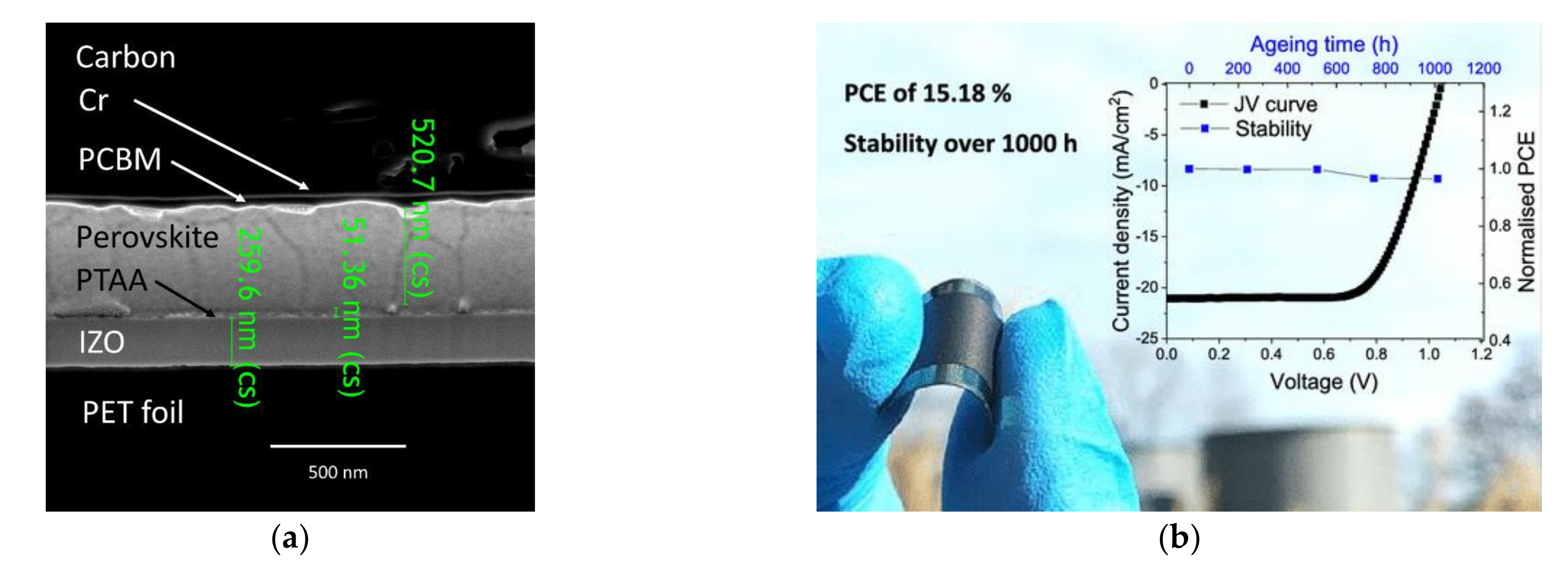
| Carbon paste | FTO/SnO2/Perovskite/ Spiro-OMeTAD/Al foil/ Carbon | 19.72 | 1.09 | 0.70 | 15.38 | [8] | |
| FTO/TiO2/Perovskite/ Carbon | 22.15 | 0.87 | 0.67 | 13.03 | [9] | ||
| ITO/SnO2/Perovskite/ Carbon | 22.19 | 1.08 | 0.57 | 13.64 | [48] | ||
| FTO/SnO2/Perovskite/CuSCN/ Carbon | 20.40 | 1.08 | 0.66 | 14.60 | [49] | ||
| FTO/TiO2/SiO2/Perovskite/ Carbon | 20.30 | 0.89 | 0.65 | 11.9 | [50] | ||
| Carbon black and graphite | FTO/TiO2/Al2O3/NiO/Perovskite/ Carbon | 21.62 | 0.92 | 0.76 | 15.03 | [51] | |
| FTO/TiO2/Perovskite/ Carbon | 20.25 | 1.05 | 0.63 | 13.50 | [52] | ||
| Drop casting | MWNTs | FTO/TiO2/Perovskite/ CuSCN/Carbon | 23.70 | 1.01 | 0.73 | 17.58 | [53] |
| FTO/ c-TiO2/ m-TiO2/ Perovskite/Carbon | 19.31 | 0.88 | 0.71 | 12.08 | [54] | ||
| Spray coating | O-MWNTs | FTO/SnO2/Perovskite/ O-MWNTs/Carbon | 21.96 | 0.99 | 0.41 | 8.99 | [55] |
| Thermal evaporation | B-MWNTs | FTO/c-TiO2/m-TiO2/ Perovskite/B-MWNTs | 21.35 | 0.90 | 0.76 | 14.60 | [56] |
| Al2O3-B-MWNTs | FTO/ TiO2/Al2O3-B-MWNTs-Perovskite | 21.50 | 0.92 | 0.77 | 15.23 | [56] | |
| Graphene | ITO/graphene/MoO3 (2 nm)/ PEDOT:PSS/Perovskite/ C60/BCP/Al/LiF | 21.20 | 0.96 | 0.70 | 1420 | [57] | |
| PEN/graphene/MoO3 (2 nm)/ PEDOT:PSS/Perovskite/ C60/BCP/Al/LiF | 20.00 | 0.97 | 0.69 | 13.30 | [57] | ||
| SWNTs | ITO/SWNT/MoO3 (2 nm)/ PEDOT:PSS/Perovskite/ C60/BCP/Al/LiF | 17.50 | 0.96 | 0.76 | 12.80 | [57] | |
| PEN/SWNT/MoO3 (2 nm)/ PEDOT:PSS/Perovskite/ C60/BCP/Al/LiF | 18.80 | 0.90 | 0.65 | 11.00 | [57] | ||
| Embedded | SWNTs | SWNT-PI/MoOx/ poly(triarylamine) (PTAA)/ Perovskite/C60/BCP/Cu | 19.00 | 1.05 | 0.76 | 15.20 | [58] |
| Laminated | TFMS-doped SWNTs | ITO/PEDOT:PSS/Perovskite/ SWNT/Spiro-MeOTAD | 22.70 | 1.12 | 0.73 | 18.80 | [59] |
| TFMS-doped SWNTs | ITO/SnO2/Perobskite/ SWNT/Spiro-MeOTAD | 24.21 | 1.00 | 0.72 | 17.60 | [60] | |
| Graphene/Carbon nanotube | FTO/TiO2/Perovskite/ Spiro-OMeTAD/ graphene/CNT | 21.88 | 1.07 | 0.45 | 15.36 | [61] | |
| Scrape coating | Carbon ink | FTO/TiO2/ZrO2/Perovskite/ Carbon | 22.38 | 0.87 | 0.50 | 9.89 | [62] |
| Screen printing | Carbon paste | FTO/TiO2/ZrO2/Perovskite/ Carbon | 21.40 | 0.88 | 0.57 | 10.70 | [38] |
| FTO/TiO2 /Perovskite (CNT drip)/Carbon | 18.97 | 1.99 | 0.71 | 13.57 | [63] | ||
| Graphite paste | FTO/TiO2/ZrO2/Perovskite/ Graphite | 22.82 | 0.90 | 0.60 | 12.40 | [64] | |
| Boron dope graphite paste | FTO/TiO2/ZrO2/Perovskite/ B-Graphite | 22.87 | 0.94 | 0.63 | 13.60 | [64] | |
| Inkjet printing | Carbon paste | FTO/TiO2/Perovskite/Carbon | 15.00 | 0.90 | 0.63 | 8.51 | [65] |
| FTO/TiO2/Perovskite/ Carbon+CH3NH3I ink | 17.20 | 0.95 | 0.71 | 11.60 | [65] | ||
| Brushing | Carbon paste | FTO/TiO2/Perovskite/Carbon | 21.27 | 1.04 | 0.65 | 14.38 | [66] |
| Substrate | PSCs Structure | Active Area (cm2) | Test Condition | Stability | PCE (%) | Humidity | Ref. |
|---|---|---|---|---|---|---|---|
| Glass | FTO/m-TiO2/ Perovskite/ Carbon | 1 | A 500 W xenon lamp (XIL model 05A50KS source units) | - | 12.63 | 80% | [63] |
| FTO/m-TiO2/ Perovskite/Carbon | 1 | The solar light simulator (Newport solar simulator, model number 6255, 150 W Xe lamp, AM 1.5 global filter) was calibrated to 1 sun (100 mW cm−2) | - | 9.72 | - | [66] | |
| FTO/ZnO/ Perovskite/ Carbon | 1 | Illumination of 100 mW/cm2 by a 450 W class AAA solar simulator equipped with an AM1.5G filter (Sol2A, Oriel Instruments) | 140 d | 15.1 | - | [68] | |
| FTO/ZnO/ Perovskite/ Carbon | 17.6 | Illumination of 100 mW/cm2 by a 450 W class AAA solar simulator equipped with an AM1.5G filter (Sol2A, Oriel Instruments) | 140 d | 10.6 | - | [68] | |
| FTO/TiO2/ZrO2/ Perovskite/ Carbon | 49 | AM1.5 illumination, without any additional UV filter and under simulated AM 1.5 100mW/cm2 sunlight. | 1000 h | 10.4 | 65–70% | [67] | |
| FTO/m-TiO2/ (Perovskite/ ZrO2/Co3O4)/ Carbon | 70 | AM 1.5G without any maskin | 2500 h | 11.39 | 70% | [69] | |
| Glass | FTO/m-TiO2/ Perovskitex/ Carbon+MAI/ Carbon | >1.1 | Illumination of 100 mAcm2, AM 1.5 illumination | 160 d | 13.04 | - | [70] |
| FTO/TiO2/ Perovskite/ Carbon | 1 | Illumination of one sun illumination | 2000 h | 6.21 | ~20% | [71] | |
| FTO/TiO2/ Perovskite/ Carbon | 0.05 | A solar light simulator (Newport solar simulator, model number 6255, 150 W Xe lamp, AM 1.5 global filter) was calibrated to 1 sun (100 mW cm−2) | - | 14.58 | - | [72] | |
| FTO/m-TiO2/ Perovskite/Carbon | 0.05 | Newport solar simulator, model number 6255, 150 W Xe lamp, AM 1.5 global filter | 120 d | 11.64 | 10–20% | [73] | |
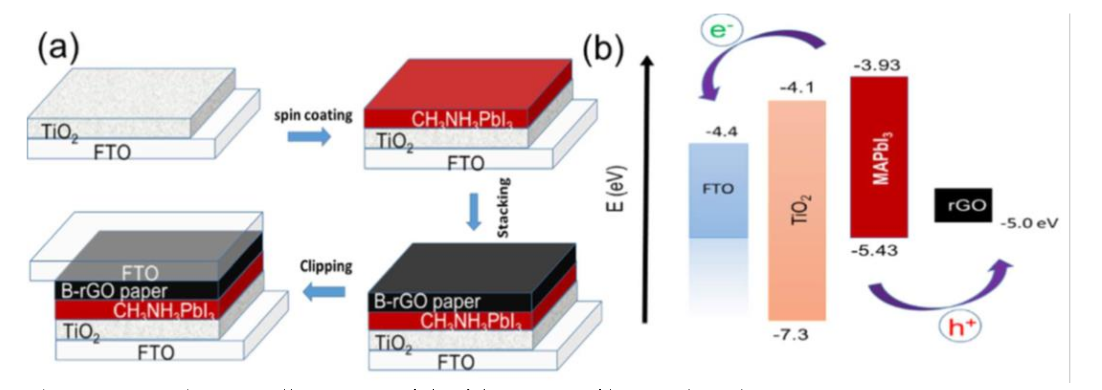
| Paper | FTO/ TiO2/ Perovskite/ B-rGO/FTO | 1 | The standard AM 1.5G conditions | 250 h | 8.96 | 60% | [28] |
Publisher’s Note: MDPI stays neutral with regard to jurisdictional claims in published maps and institutional affiliations. |
© 2021 by the authors. Licensee MDPI, Basel, Switzerland. This article is an open access article distributed under the terms and conditions of the Creative Commons Attribution (CC BY) license (https://creativecommons.org/licenses/by/4.0/).
Share and Cite
Pradid, P.; Sanglee, K.; Thongprong, N.; Chuangchote, S. Carbon Electrodes in Perovskite Photovoltaics. Materials 2021, 14, 5989. https://doi.org/10.3390/ma14205989
Pradid P, Sanglee K, Thongprong N, Chuangchote S. Carbon Electrodes in Perovskite Photovoltaics. Materials. 2021; 14(20):5989. https://doi.org/10.3390/ma14205989
Chicago/Turabian StylePradid, Preawpun, Kanyanee Sanglee, Non Thongprong, and Surawut Chuangchote. 2021. "Carbon Electrodes in Perovskite Photovoltaics" Materials 14, no. 20: 5989. https://doi.org/10.3390/ma14205989
APA StylePradid, P., Sanglee, K., Thongprong, N., & Chuangchote, S. (2021). Carbon Electrodes in Perovskite Photovoltaics. Materials, 14(20), 5989. https://doi.org/10.3390/ma14205989