
Review of Organic Photorefractive Materials and Their Use for Updateable 3D Display


Abstract
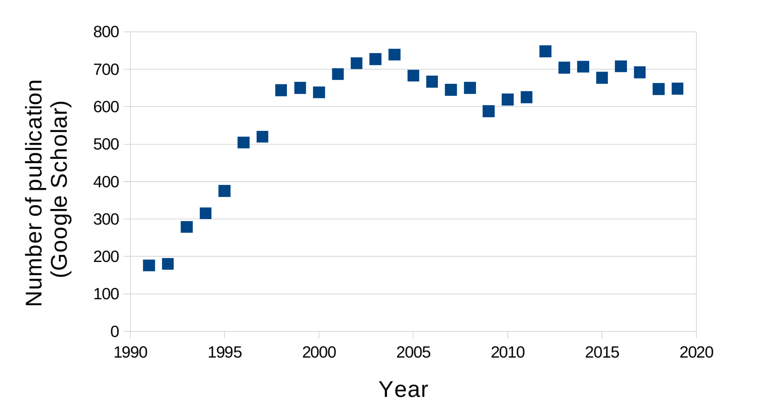
1. Introduction
2. Overview of the Photorefractive Effect
3. Photorefractive Effect in Polymers
3.1. Electronic Behavior in Molecules
- Charge photo-generation ↔ sensitizer molecules.
- Charge transport ↔ polymer chains.
- Charge trapping ↔ conformational traps.
- Space-charge field ↔ electron and hole differential relocation.
- Index modulation ↔ chromophore molecules.
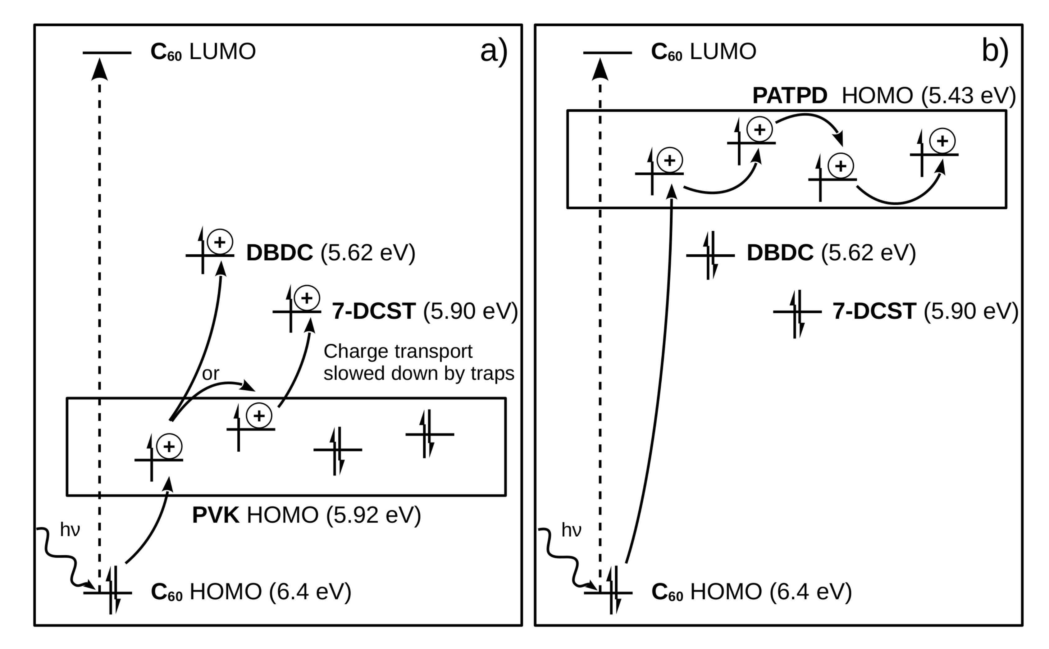
3.2. Matching Energy Levels
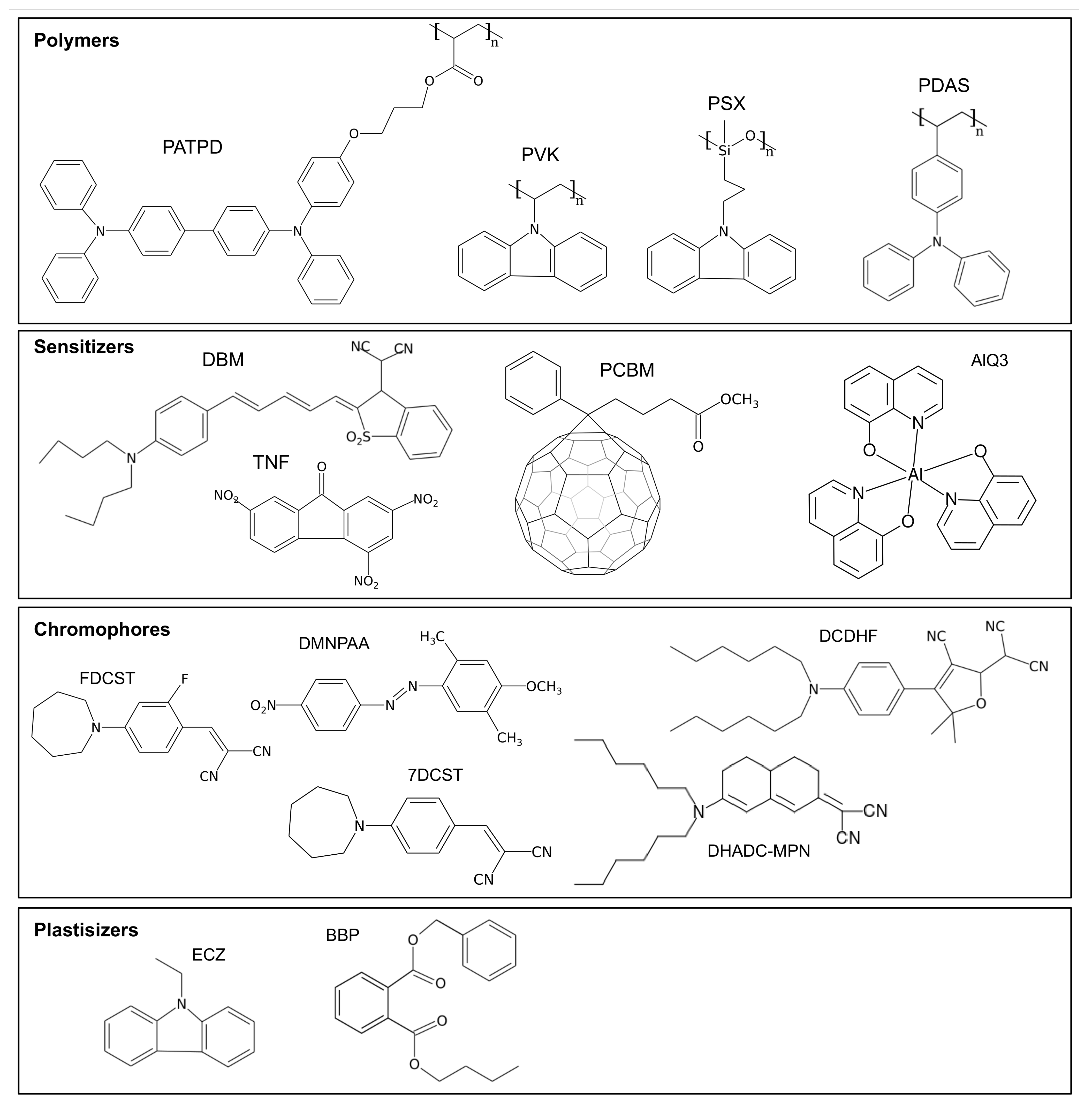
3.3. Molecular Species in Photorefractive Polymers
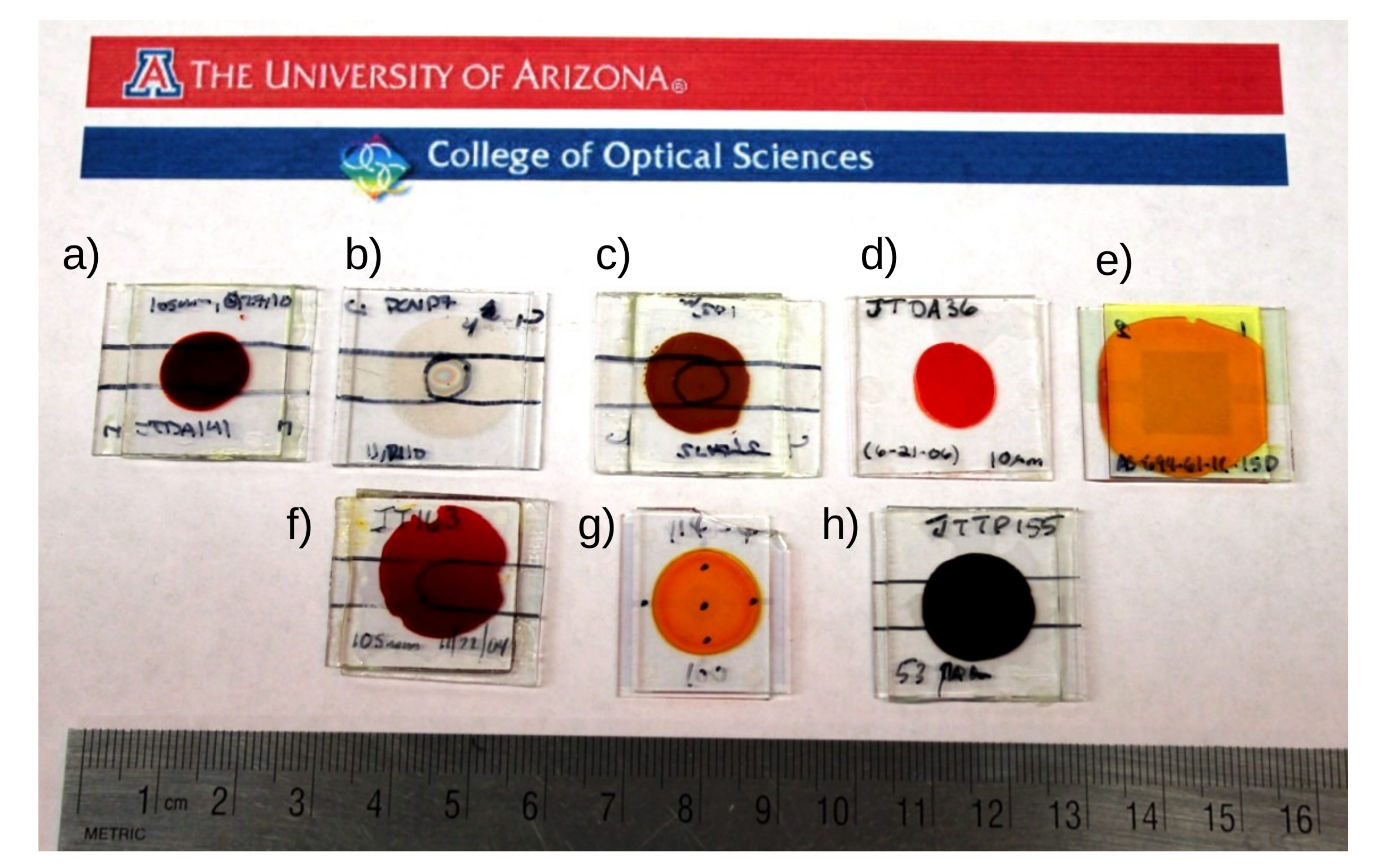
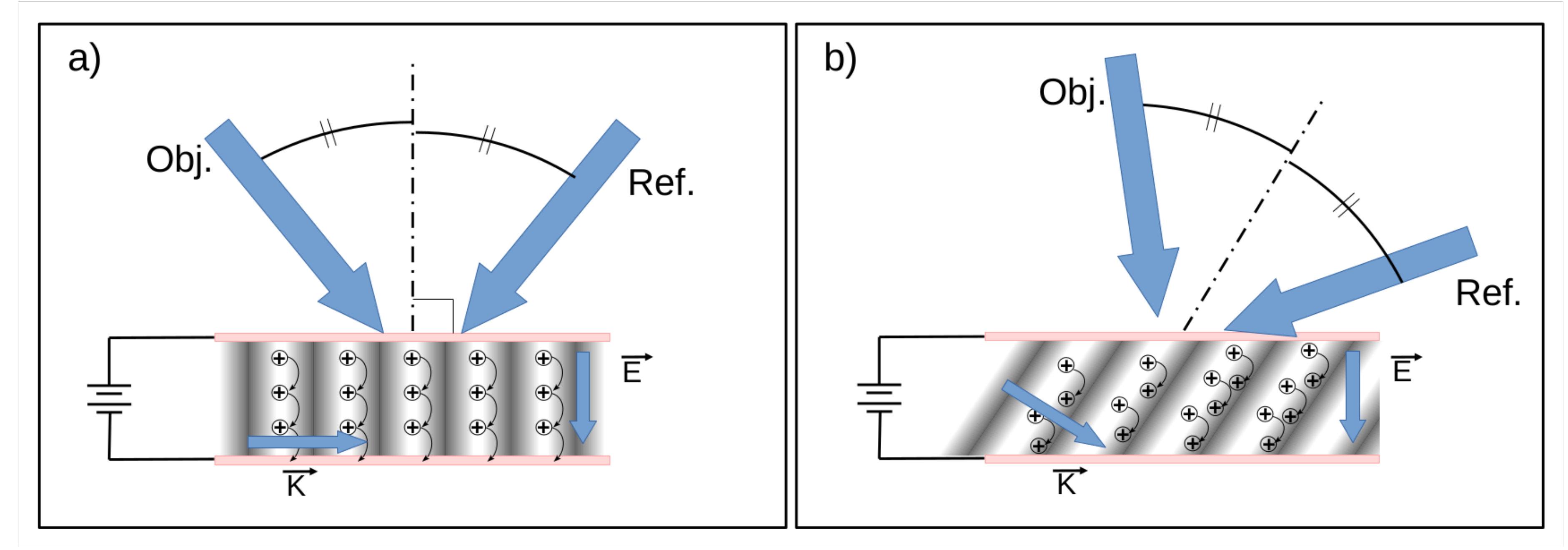
4. External Field and Sample Geometry
5. Photorefractive-Based 3D Display
5.1. Early Works and Rational
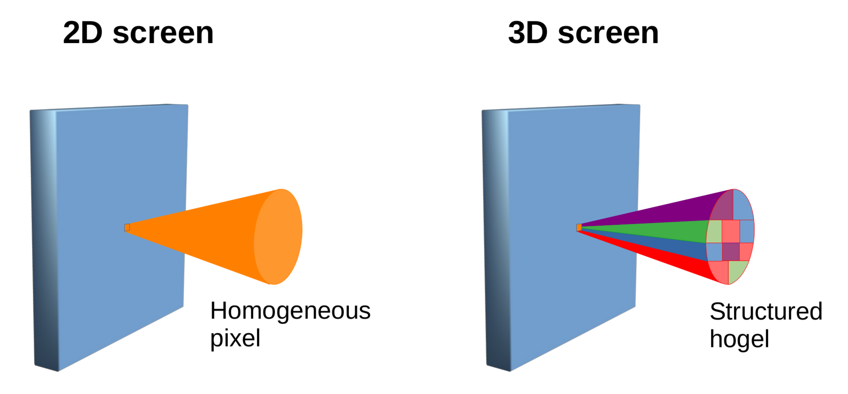
5.2. Holographic Stereograms
5.3. Display Engineering: Ever Faster
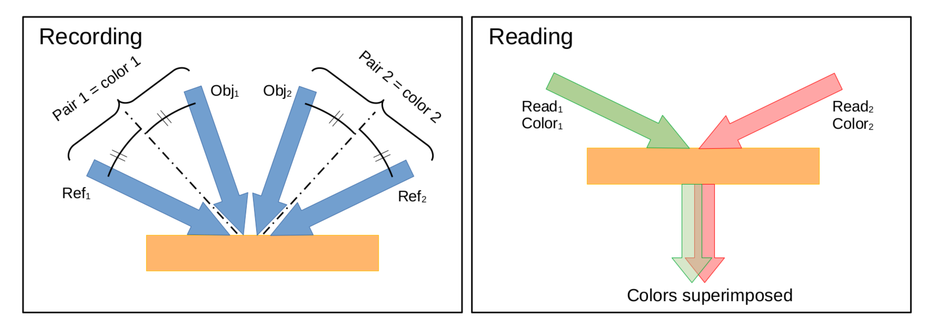
5.4. Full Color Holograms: Angular and Polarization Multiplexing
6. Conclusions
Author Contributions
Funding
Institutional Review Board Statement
Informed Consent Statement
Data Availability Statement
Conflicts of Interest
References
- Leith, E.N.; Upatnieks, J. New techniques in wavefront reconstruction. J. Opt. Soc. Am 1961, 51, 1469–1473. [Google Scholar]
- Denisyuk, Y.N. On the reflection of optical properties of an object in a wave field of light scattered by it. Dokl. Akad. Nauk SSSR 1962, 144, 1275–1278. [Google Scholar]
- Dunn, D.; Tursun, O.; Yu, H.; Didyk, P.; Myszkowski, K.; Fuchs, H. Stimulating the Human Visual System Beyond Real World Performance in Future Augmented Reality Displays. In Proceedings of the 2020 IEEE International Symposium on Mixed and Augmented Reality (ISMAR), Porto de Galinhas, Brazil, 9–13 November 2020; pp. 90–100. [Google Scholar]
- Howard, I.P. Perceiving in Depth, Volume 1: Basic Mechanisms; Oxford University Press: Oxford, UK, 2012. [Google Scholar]
- Park, M.C.; Mun, S. Overview of measurement methods for factors affecting the human visual system in 3D displays. J. Disp. Technol. 2015, 11, 877–888. [Google Scholar] [CrossRef]
- Blanche, P.A. Toward the Ultimate 3-D Display. Inf. Disp. 2012, 28, 32–37. [Google Scholar] [CrossRef]
- Matsushima, K. Introduction to Computer Holography: Creating Computer-Generated Holograms as the Ultimate 3D Image; Springer Nature: Basingstoke, UK, 2020. [Google Scholar]
- Bjelkhagen, H.; Brotherton-Ratcliffe, D. Ultra-Realistic Imaging: Advanced Techniques in Analogue and Digital Colour Holography; CRC Press: Boca Raton, FL, USA, 2013. [Google Scholar]
- Upatnieks, J.; Marks, J.; Fedorowicz, R. Color holograms for white light reconstruction. Appl. Phys. Lett. 1966, 8, 286–287. [Google Scholar] [CrossRef]
- Bjelkhagen, H. Colour holography: The ultimate 3D imaging technique. Imaging Sci. J. 2011, 59, 83–89. [Google Scholar] [CrossRef]
- Siebert, L. Large-scene front-lighted hologram of a human subject. Proc. IEEE 1968, 56, 1242–1243. [Google Scholar] [CrossRef]
- Benton, S.A. Hologram reconstruction with extended incoherent sources. J. Opt. Soc. Am. 1969, 59, 1545. [Google Scholar]
- Sarakinos, A.; Lembessis, A. Color Holography for the Documentation and Dissemination of Cultural Heritage: OptoClonesTM from Four Museums in Two Countries. J. Imaging 2019, 5, 59. [Google Scholar] [CrossRef]
- Gentet, P.; Gentet, Y.; Choi, P.H.; Lee, S.H. Evaluation of the realism of a full-color reflection H2 analog hologram recorded on ultra-fine-grain silver-halide material. Open Phys. 2019, 17, 449–457. [Google Scholar] [CrossRef]
- De Bitetto, D. A holographic motion picture film with constant velocity transport. Appl. Phys. Lett. 1968, 12, 295–297. [Google Scholar] [CrossRef]
- Jacobson, A.; Evtuhov, V.; Neeland, J. Motion picture holography. Appl. Phys. Lett. 1969, 14, 120–122. [Google Scholar] [CrossRef]
- Bove, V.M., Jr. Holographic television. In Optical Holography; Elsevier: Amsterdam, The Netherlands, 2020; pp. 73–82. [Google Scholar]
- Slinger, C.; Cameron, C.; Stanley, M. Computer-generated holography as a generic display technology. Computer 2005, 38, 46–53. [Google Scholar] [CrossRef]
- An, J.; Won, K.; Kim, Y.; Hong, J.Y.; Kim, H.; Kim, Y.; Song, H.; Choi, C.; Kim, Y.; Seo, J.; et al. Slim-panel holographic video display. Nat. Commun. 2020, 11, 1–7. [Google Scholar] [CrossRef] [PubMed]
- Jolly, S.; Savidis, N.; Datta, B.; Smalley, D.; Bove, V.M., Jr. Progress in transparent flat-panel holographic displays enabled by guided-wave acousto-optics. In Practical Holography XXXII: Displays, Materials, and Applications; International Society for Optics and Photonics: Bellingham, DC, USA, 2018; Volume 10558, p. 105580L. [Google Scholar]
- Ashkin, A.; Boyd, G.; Dziedzic, J.I.; Smith, R.; Ballman, A.; Levinstein, J.; Nassau, K. Optically-induced refractive index inhomogeneities in LiNbO3 and LiTaO3. Appl. Phys. Lett. 1966, 9, 72–74. [Google Scholar] [CrossRef]
- Sutter, K.; Hulliger, J.; Günter, P. Photorefractive effects observed in the organic crystal 2-cyclooctylamino-5-nitropyridine doped with 7, 7, 8, 8-tetracyanoquinodimethane. Solid State Commun. 1990, 74, 867–870. [Google Scholar] [CrossRef]
- Ducharme, S.P.; Scott, J.; Twieg, R.; Moerner, W. Observation of the photorefractive effect in a polymer. Phys. Rev. Lett. 1991, 66, 1846. [Google Scholar] [CrossRef]
- Chen, F. A Laser-Induced Inhomogeneity of Refractive Indices in KTN. J. Appl. Phys. 1967, 38, 3418–3420. [Google Scholar] [CrossRef]
- Christodoulides, D.N.; Coskun, T.H.; Mitchell, M.; Segev, M. Theory of incoherent self-focusing in biased photorefractive media. Phys. Rev. Lett. 1997, 78, 646. [Google Scholar] [CrossRef]
- Feinberg, J. Asymmetric self-defocusing of an optical beam from the photorefractive effect. JOSA 1982, 72, 46–51. [Google Scholar] [CrossRef]
- Walsh, C.; Moerner, W. Two-beam coupling measurements of grating phase in a photorefractive polymer. JOSA B 1992, 9, 1642–1647. [Google Scholar] [CrossRef]
- Cronin-Golomb, M.; Fischer, B.; White, J.; Yariv, A. Theory and applications of four-wave mixing in photorefractive media. IEEE J. Quantum Electron. 1984, 20, 12–30. [Google Scholar] [CrossRef]
- Poga, C.; Lundquist, P.; Lee, V.; Shelby, R.; Twieg, R.; Burland, D. Polysiloxane-based photorefractive polymers for digital holographic data storage. Appl. Phys. Lett. 1996, 69, 1047–1049. [Google Scholar] [CrossRef]
- Kippelen, B.; Peyghambarian, N.; Lyon, S.; Padias, A.; Hall, H. New highly efficient photorefractive polymer composite for optical-storage and image-processing applications. Electron. Lett. 1993, 29, 1873–1874. [Google Scholar] [CrossRef]
- Steele, D.; Volodin, B.; Savina, O.; Kippelen, B.; Peyghambarian, N.; Röckel, H.; Marder, S. Transillumination imaging through scattering media by use of photorefractive polymers. Opt. Lett. 1998, 23, 153–155. [Google Scholar] [CrossRef][Green Version]
- Blanche, P.A.; Bablumian, A.; Voorakaranam, R.; Christenson, C.; Lin, W.; Gu, T.; Flores, D.; Wang, P.; Hsieh, W.Y.; Kathaperumal, M.; et al. Holographic three-dimensional telepresence using large-area photorefractive polymer. Nature 2010, 468, 80–83. [Google Scholar] [CrossRef] [PubMed]
- Günter, P.; Huignard, J.P. Photorefractive Materials and Their Applications; Springer: Berlin/Heidelberg, Germany, 2007; Volume 114. [Google Scholar]
- Blanche, P.A. Photorefractive Organic Materials and Applications; Springer: Berlin/Heidelberg, Germany, 2016; Volume 240. [Google Scholar]
- Fuentes-Hernandez, C.; Suh, D.J.; Kippelen, B.; Marder, S.R. High-performance photorefractive polymers sensitized by cadmium selenide nanoparticles. Appl. Phys. Lett. 2004, 85, 534–536. [Google Scholar] [CrossRef]
- Tay, S.; Thomas, J.; Eralp, M.; Li, G.; Norwood, R.A.; Schülzgen, A.; Yamamoto, M.; Barlow, S.; Walker, G.A.; Marder, S.R. High-performance photorefractive polymer operating at 1550 nm with near-video-rate response time. Appl. Phys. Lett. 2005, 87, 171105. [Google Scholar] [CrossRef]
- Marder, S.R.; Kippelen, B.; Jen, A.K.Y.; Peyghambarian, N. Design and synthesis of chromophores and polymers for electro-optic and photorefractive applications. Nature 1997, 388, 845–851. [Google Scholar] [CrossRef]
- Thomas, J.; Eralp, M.; Tay, S.; Li, G.; Yamamoto, M.; Norwood, R.A.; Marder, S.R.; Peyghambarian, N.N. Photorefractive polymers with superior performance. Opt. Photonics News 2005, 16, 31. [Google Scholar]
- Fuentes-Hernandez, C.; Thomas, J.; Termine, R.; Meredith, G.; Peyghambarian, N.; Kippelen, B.; Barlow, S.; Walker, G.; Marder, S.R.; Yamamoto, M.; et al. Video-rate compatible photorefractive polymers with stable dynamic properties under continuous operation. Appl. Phys. Lett. 2004, 85, 1877–1879. [Google Scholar] [CrossRef]
- Eralp, M.; Thomas, J.; Tay, S.; Li, G.; Schülzgen, A.; Norwood, R.; Yamamoto, M.; Peyghambarian, N. Submillisecond response of a photorefractive polymer under single nanosecond pulse exposure. Appl. Phys. Lett. 2006, 89, 114105. [Google Scholar] [CrossRef]
- Kippelen, B.; Meyers, F.; Peyghambarian, N.; Marder, S.R. Chromophore design for photorefractive applications. J. Am. Chem. Soc. 1997, 119, 4559–4560. [Google Scholar] [CrossRef]
- Kippelen, B.; Marder, S.; Hendrickx, E.; Maldonado, J.; Guillemet, G.; Volodin, B.; Steele, D.; Enami, Y.; Yao, Y.; Wang, J.; et al. Infrared photorefractive polymers and their applications for imaging. Science 1998, 279, 54–57. [Google Scholar] [CrossRef]
- Eralp, M.; Thomas, J.; Tay, S.; Li, G.; Meredith, G.; Schülzgen, A.; Peyghambarian, N.; Walker, G.A.; Barlow, S.; Marder, S.R. High-performance photorefractive polymer operating at 975 nm. Appl. Phys. Lett. 2004, 85, 1095–1097. [Google Scholar] [CrossRef]
- Thomas, J.; Fuentes-Hernandez, C.; Yamamoto, M.; Cammack, K.; Matsumoto, K.; Walker, G.A.; Barlow, S.; Kippelen, B.; Meredith, G.; Marder, S.R.; et al. Bistriarylamine Polymer-Based Composites for Photorefractive Applications. Adv. Mater. 2004, 16, 2032–2036. [Google Scholar] [CrossRef]
- Kippelen, B.; Blanche, P.A.; Schülzgen, A.; Fuentes-Hernandez, C.; Ramos-Ortiz, G.; Wang, J.F.; Peyghambarian, N.; Marder, S.R.; Leclercq, A.; Beljonne, D.; et al. Photorefractive Polymers with Non-Destructive Readout. Adv. Funct. Mater. 2002, 12, 615–620. [Google Scholar] [CrossRef]
- Kippelen, B.; Golemme, A.; Hendrickx, E.; Wang, J.F.; Marder, S.R.; Peyghambarian, N. Photorefractive Polymers and Polymer-Dispersed Liquid Crystals. In Field Responsive Polymers; ACS: Washington, DC, USA, 1999; Chapter 14; pp. 204–225. [Google Scholar] [CrossRef]
- Herlocker, J.; Fuentes-Hernandez, C.; Wang, J.; Peyghambarian, N.; Kippelen, B.; Zhang, Q.; Marder, S. Photorefractive polymer composites fabricated by injection molding. Appl. Phys. Lett. 2002, 80, 1156–1158. [Google Scholar] [CrossRef]
- Hendrickx, E.; Herlocker, J.; Maldonado, J.; Marder, S.; Kippelen, B.; Persoons, A.; Peyghambarian, N. Thermally stable high-gain photorefractive polymer composites based on a tri-functional chromophore. Appl. Phys. Lett. 1998, 72, 1679–1681. [Google Scholar] [CrossRef]
- Herlocker, J.; Fuentes-Hernandez, C.; Ferrio, K.; Hendrickx, E.; Blanche, P.A.; Peyghambarian, N.; Kippelen, B.; Zhang, Y.; Wang, J.; Marder, S. Stabilization of the response time in photorefractive polymers. Appl. Phys. Lett. 2000, 77, 2292–2294. [Google Scholar] [CrossRef]
- Onsager, L. Initial recombination of ions. Phys. Rev. 1938, 54, 554. [Google Scholar] [CrossRef]
- Mozumder, A. Effect of an external electric field on the yield of free ions. I General results from the Onsager theory. J. Chem. Phys. 1974, 60, 4300–4304. [Google Scholar] [CrossRef]
- Blanche, P.A.; Kippelen, B.; Schülzgen, A.; Fuentes-Hernandez, C.; Ramos-Ortiz, G.; Wang, J.; Hendrickx, E.; Peyghambarian, N.; Marder, S. Photorefractive polymers sensitized by two-photon absorption. Opt. Lett. 2002, 27, 19–21. [Google Scholar] [CrossRef]
- Tay, S.; Thomas, J.; Eralp, M.; Li, G.; Kippelen, B.; Marder, S.R.; Meredith, G.; Schülzgen, A.; Peyghambarian, N. Photorefractive polymer composite operating at the optical communication wavelength of 1550 nm. Appl. Phys. Lett. 2004, 85, 4561–4563. [Google Scholar] [CrossRef][Green Version]
- Moharam, M.; Young, L. Hologram writing by the photorefractive effect. J. Appl. Phys. 1977, 48, 3230–3236. [Google Scholar] [CrossRef]
- Moharam, M.; Gaylord, T.; Magnusson, R.; Young, L. Holographic grating formation in photorefractive crystals with arbitrary electron transport lengths. J. Appl. Phys. 1979, 50, 5642–5651. [Google Scholar] [CrossRef]
- Kukhtarev, N.V.; Markov, V.; Odulov, S. Transient energy transfer during hologram formation in LiNbO3 in external electric field. Opt. Commun. 1977, 23, 338–343. [Google Scholar] [CrossRef]
- Kukhtarev, N.; Markov, V.; Odulov, S.; Soskin, M.; Vinetskii, V. Holographic storage in electrooptic crystals. i. steady state. Ferroelectrics 1978, 22, 949–960. [Google Scholar] [CrossRef]
- Hendrickx, E.; Kippelen, B.; Thayumanavan, S.; Marder, S.R.; Persoons, A.; Peyghambarian, N. High photogeneration efficiency of charge-transfer complexes formed between low ionization potential arylamines and C60. J. Chem. Phys. 2000, 112, 9557–9561. [Google Scholar] [CrossRef]
- Masumura, K.; Nakanishi, I.; Khuat, K.V.T.; Kinashi, K.; Sakai, W.; Tsutsumi, N. Optimal composition of the poly (triarylamine)-based polymer composite to maximize photorefractive performance. Sci. Rep. 2019, 9, 1–9. [Google Scholar] [CrossRef]
- Giang, H.N.; Sassa, T.; Fujihara, T.; Tsujimura, S.; Kinashi, K.; Sakai, W.; Wada, S.; Tsutsumi, N. Triphenylamine-Based Plasticizer in Controlling Traps and Photorefractivity Enhancement. ACS Appl. Electron. Mater. 2021, 3, 2170–2177. [Google Scholar] [CrossRef]
- Chantharasupawong, P.; Christenson, C.W.; Philip, R.; Zhai, L.; Winiarz, J.; Yamamoto, M.; Tetard, L.; Nair, R.R.; Thomas, J. Photorefractive performances of a graphene-doped PATPD/7-DCST/ECZ composite. J. Mater. Chem. C 2014, 2, 7639–7647. [Google Scholar] [CrossRef]
- Hales, J.M.; Barlow, S.; Kim, H.; Mukhopadhyay, S.; Brédas, J.L.; Perry, J.W.; Marder, S.R. Design of organic chromophores for all-optical signal processing applications. Chem. Mater. 2014, 26, 549–560. [Google Scholar] [CrossRef]
- Moerner, W.E.; Silence, S.; Hache, F.; Bjorklund, G.C. Orientationally enhanced photorefractive effect in polymers. JOSA B 1994, 11, 320–330. [Google Scholar] [CrossRef]
- Hendrickx, E.; Guenther, B.; Zhang, Y.; Wang, J.; Staub, K.; Zhang, Q.; Marder, S.; Kippelen, B.; Peyghambarian, N. Ellipsometric determination of the electric-field-induced birefringence of photorefractive dyes in a liquid carbazole derivative. Chem. Phys. 1999, 245, 407–415. [Google Scholar] [CrossRef]
- Ribierre, J.C.; Cheval, G.; Huber, F.; Mager, L.; Fort, A.; Muller, R.; Mery, S.; Nicoud, J. Direct comparison of mechanical and electro-optic responses of a low T g photorefractive doped polymer. J. Appl. Phys. 2002, 91, 1710–1712. [Google Scholar] [CrossRef]
- Han, J.; Xu, Q.; Chen, J.; Zhu, L. Nonlinear super-resolution imaging via orientationally enhanced photorefractive effect in polymer. Opt. Lett. 2021, 46, 2441–2444. [Google Scholar] [CrossRef]
- Lynn, B.; Miles, A.; Mehravar, S.; Blanche, P.A.; Kieu, K.; Norwood, R.A.; Peyghambarian, N. Real-time imaging of chromophore alignment in photorefractive polymer devices through multiphoton microscopy. MRS Commun. 2015, 5, 243–250. [Google Scholar] [CrossRef][Green Version]
- Marder, S.R.; Perry, J.W. Molecular materials for second-order nonlinear optical applications. Adv. Mater. 1993, 5, 804–815. [Google Scholar] [CrossRef]
- Volodin, B.; Kippelen, B.; Meerholz, K.; Javidi, B.; Peyghambarian, N. A polymeric optical pattern-recognition system for security verification. Nature 1996, 383, 58–60. [Google Scholar] [CrossRef]
- Kim, W.S.; Lee, J.W.; Park, J.K. Enhancement of the recording stability of a photorefractive polymer composite by the introduction of a trapping layer. Appl. Phys. Lett. 2003, 83, 3045–3047. [Google Scholar] [CrossRef]
- Christenson, C.W.; Thomas, J.; Blanche, P.A.; Voorakaranam, R.; Norwood, R.A.; Yamamoto, M.; Peyghambarian, N. Complementary grating dynamics in photorefractive polymers with Alq3. In Organic Photonic Materials and Devices XII; International Society for Optics and Photonics: Bellingham, DC, USA, 2010; Volume 7599, p. 759905. [Google Scholar]
- Wang, K.L.; Jiang, J.C.; Jhu, C.H.; Wada, S.; Sassa, T.; Horie, M. High-performance organic photorefractive materials containing 2-ethylhexyl plasticized poly (triarylamine). J. Mater. Chem. C 2020, 8, 13357–13367. [Google Scholar] [CrossRef]
- Masumura, K.; Oka, T.; Kinashi, K.; Sakai, W.; Tsutsumi, N. Photorefractive dynamics in poly (triarylamine)-based polymer composite: An approach utilizing a second electron trap to reduce the photoconductivity. Opt. Mater. Express 2018, 8, 401–412. [Google Scholar] [CrossRef]
- Choi, J.; Moon, J.S.; Kim, F.S.; Oh, J.W. Fast photorefractive response in polymeric composites enabled by the control of chromophore free volume. Opt. Lett. 2018, 43, 3289–3292. [Google Scholar] [CrossRef]
- Choi, J.; Kim, M.I.; Kim, F.S.; Kim, N.; Oh, J.W.; Moon, J.S. Enhancement of the response time in organic photorefractive composites using alkoxy-substituted PDCST as a nonlinear optical chromophore. Opt. Lett. 2020, 45, 6767–6770. [Google Scholar] [CrossRef] [PubMed]
- Moon, I.K.; Choi, C.S.; Kim, N. Synthesis and characterization of a low-Tg photorefractive composite. J. Photochem. Photobiol. A Chem. 2009, 202, 57–62. [Google Scholar] [CrossRef]
- Tay, S.; Blanche, P.A.; Voorakaranam, R.; Tunç, A.; Lin, W.; Rokutanda, S.; Gu, T.; Flores, D.; Wang, P.; Li, G.; et al. An updatable holographic three-dimensional display. Nature 2008, 451, 694–698. [Google Scholar] [CrossRef]
- Zhang, K.; Yang, H.; Li, M.; Li, J.; Wu, W.; Xu, S.; Liu, Y.; Cao, S. A hyperbranched polymer with enhanced photorefractive effect at low and zero applied electric field. Dyes Pigment. 2020, 180, 108473. [Google Scholar] [CrossRef]
- Chen, B.; Yu, Y.; Liu, Q.; Chen, S.; Luo, X.; Wang, F.; Zhang, Q.; Wu, W. Photorefractive polymeric composites with high two-beam coupling gain without external electric field. Optik 2019, 179, 895–900. [Google Scholar] [CrossRef]
- Chen, B.; Liu, Q.; Li, X.; Yu, Y.; Luo, X.; Wang, F.; Zhang, Q.; Chen, S.; Wu, W. Facile organic photorefractive (PR) composites with favorable PR performance under no external electric field. Opt. Mater. 2019, 91, 80–84. [Google Scholar] [CrossRef]
- Ketchel, B.P.; Wood, G.L.; Anderson, R.J.; Salamo, G.J. Three-dimensional image reconstruction using strontium barium niobate. Appl. Phys. Lett. 1997, 71, 7–9. [Google Scholar] [CrossRef][Green Version]
- Ketchel, B.P.; Heid, C.A.; Wood, G.L.; Miller, M.J.; Mott, A.G.; Anderson, R.J.; Salamo, G.J. Three-dimensional color holographic display. Appl. Opt. 1999, 38, 6159–6166. [Google Scholar] [CrossRef]
- Zheng, D.; Wang, W.; Wang, S.; Qu, D.; Liu, H.; Kong, Y.; Liu, S.; Chen, S.; Rupp, R.; Xu, J. Real-time dynamic holographic display realized by bismuth and magnesium co-doped lithium niobate. Appl. Phys. Lett. 2019, 114, 241903. [Google Scholar] [CrossRef]
- Blanche, P.A.; Lynn, B.; Churin, D.; Kieu, K.; Norwood, R.A.; Peyghambarian, N. Diffraction response of photorefractive polymers over nine orders of magnitude of pulse duration. Sci. Rep. 2016, 6, 1–9. [Google Scholar] [CrossRef]
- Giang, H.N.; Kinashi, K.; Sakai, W.; Tsutsumi, N. Photorefractive response and real-time holographic application of a poly (4-(diphenylamino) benzyl acrylate)-based composite. Polym. J. 2014, 46, 59–66. [Google Scholar] [CrossRef]
- Moon, J.S.; Stevens, T.E.; Monson, T.C.; Huber, D.L.; Jin, S.H.; Oh, J.W.; Winiarz, J.G. Sub-millisecond response time in a photorefractive composite operating under CW conditions. Sci. Rep. 2016, 6, 1–12. [Google Scholar] [CrossRef] [PubMed]
- Zhou, P.; Li, Y.; Liu, S.; Su, Y. Colour 3D holographic display based on a quantum-dot-doped liquid crystal. Liq. Cryst. 2019, 46, 1478–1484. [Google Scholar] [CrossRef]
- McCrickerd, J.T.; George, N. Holographic stereogram from sequential component photographs. Appl. Phys. Lett. 1968, 12, 10–12. [Google Scholar] [CrossRef]
- DeBitetto, D.J. Holographic panoramic stereograms synthesized from white light recordings. Appl. Opt. 1969, 8, 1740–1741. [Google Scholar] [CrossRef] [PubMed]
- Lucente, M. Diffraction-Specific Fringe Computation for Electro-Holography. Ph.D. Thesis, Massachusetts Institute of Technology, Cambridge, MA, USA, 1994. [Google Scholar]
- Hesselink, L.; Orlov, S.S.; Bashaw, M.C. Holographic data storage systems. Proc. IEEE 2004, 92, 1231–1280. [Google Scholar] [CrossRef]
- Coufal, H.J.; Psaltis, D.; Sincerbox, G.T. Holographic Data Storage; Springer: Berlin/Heidelberg, Germany, 2000; Volume 8. [Google Scholar]
- Wang, Z.; Lv, G.; Feng, Q.; Wang, A.; Ming, H. Resolution priority holographic stereogram based on integral imaging with enhanced depth range. Opt. Express 2019, 27, 2689–2702. [Google Scholar] [CrossRef] [PubMed]
- Fachada, S.; Bonatto, D.; Lafruit, G. High-quality holographic stereogram generation using four RGBD images. Appl. Opt. 2021, 60, A250–A259. [Google Scholar] [CrossRef] [PubMed]
- Liu, J.P.; Lu, S.L. Fast calculation of high-definition depth-added computer-generated holographic stereogram by spectrum-domain look-up table. Appl. Opt. 2021, 60, A104–A110. [Google Scholar] [CrossRef] [PubMed]
- Bartlett, T.A.; McDonald, W.C.; Hall, J.N.; Oden, P.I.; Doane, D.; Ketchum, R.S.; Byrum, T. Recent advances in the development of the Texas Instruments phase-only microelectromechanical systems (MEMS) spatial light modulator. In Emerging Digital Micromirror Device Based Systems and Applications XIII; International Society for Optics and Photonics: Bellingham, DC, USA, 2021; Volume 11698, p. 116980O. [Google Scholar]
- Ketchum, R.S.; Blanche, P.A. Diffraction Efficiency Characteristics for MEMS-Based Phase-Only Spatial Light Modulator with Nonlinear Phase Distribution. Photonics 2021, 8, 62. [Google Scholar] [CrossRef]
- Blanche, P.A.J.; Bigler, C.M.; Ka, J.W.; Peyghambarian, N.N. Fast and continuous recording of refreshable holographic stereograms. Opt. Eng. 2018, 57, 061608. [Google Scholar] [CrossRef]


| Name (wt%) | Recording Power (* Energy) Density | Recording Time | Applied E Field (V/m) | Reference |
|---|---|---|---|---|
| PATPD/CAAN:FDCST:ECZ | ||||
| (50:30:20) | 100 mW/cm | 2 s | 90 | [77] |
| PDAA:7-DCST:BBP:PCBM | ||||
| (55:40:4:1) | 172 mW/cm | 0.5 s | 40 | [85] |
| TPD:CAAN/FDCST:BBP:PCBM | ||||
| (56.2:33.7:9.8:0.2) | 1000 mW/cm | 30 ms | 72 | [84] |
| C:PbS:PATPD:PVK:7-DCST:ECZ | ||||
| (31.5:35:30:0.5:3) | 1275 mW/cm | 1 ms | 10 | [86] |
| PTAA:PDCST:TAA:PCBM:BPhen | ||||
| (31.5:35:30:0.5:3) | 534 mW/cm | 0.5 ms | 12 | [59] |
| PATPD/CAAN:FDCST:ECZ:PCBM | ||||
| (49.5:30:20:0.5) | 650 mJ/cm(*) | 6 ns | 70 | [32] |
Publisher’s Note: MDPI stays neutral with regard to jurisdictional claims in published maps and institutional affiliations. |
© 2021 by the authors. Licensee MDPI, Basel, Switzerland. This article is an open access article distributed under the terms and conditions of the Creative Commons Attribution (CC BY) license (https://creativecommons.org/licenses/by/4.0/).
Share and Cite
Blanche, P.-A.; Ka, J.-W.; Peyghambarian, N. Review of Organic Photorefractive Materials and Their Use for Updateable 3D Display. Materials 2021, 14, 5799. https://doi.org/10.3390/ma14195799
Blanche P-A, Ka J-W, Peyghambarian N. Review of Organic Photorefractive Materials and Their Use for Updateable 3D Display. Materials. 2021; 14(19):5799. https://doi.org/10.3390/ma14195799
Chicago/Turabian StyleBlanche, Pierre-Alexandre, Jae-Won Ka, and Nasser Peyghambarian. 2021. "Review of Organic Photorefractive Materials and Their Use for Updateable 3D Display" Materials 14, no. 19: 5799. https://doi.org/10.3390/ma14195799
APA StyleBlanche, P.-A., Ka, J.-W., & Peyghambarian, N. (2021). Review of Organic Photorefractive Materials and Their Use for Updateable 3D Display. Materials, 14(19), 5799. https://doi.org/10.3390/ma14195799