
Effect of Heat Treatment on Microstructure and Selective Corrosion of LPBF-AlSi10Mg by Means of SKPFM and Exo-Electron Emission

 ,
,  ,
,  ,
,  ,
,  ,
,  ,
, 
Abstract
:1. Introduction
2. Materials and Methods
2.1. Materials and Specimens
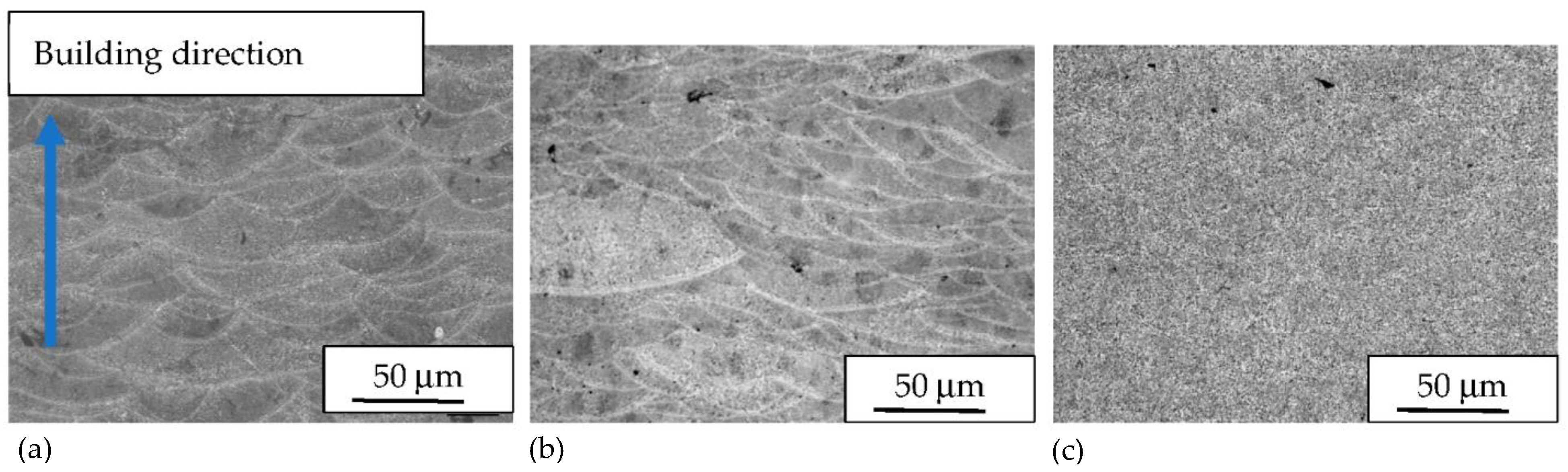
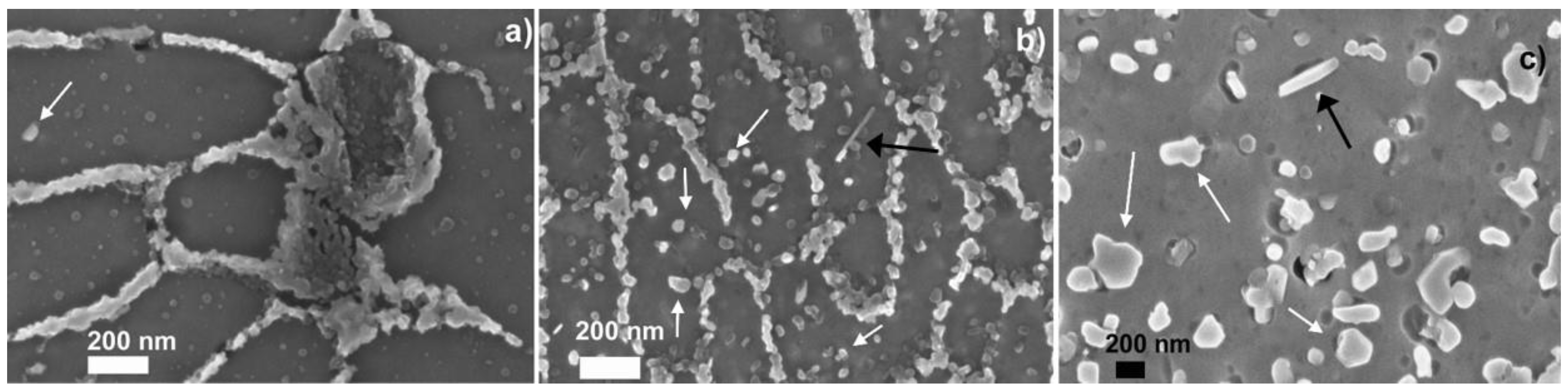
2.2. Optical and Field-Emission Scanning Electron Microscopy/Energy-Dispersive X-ray Spectroscopy (FESEM/EDS) Analysis
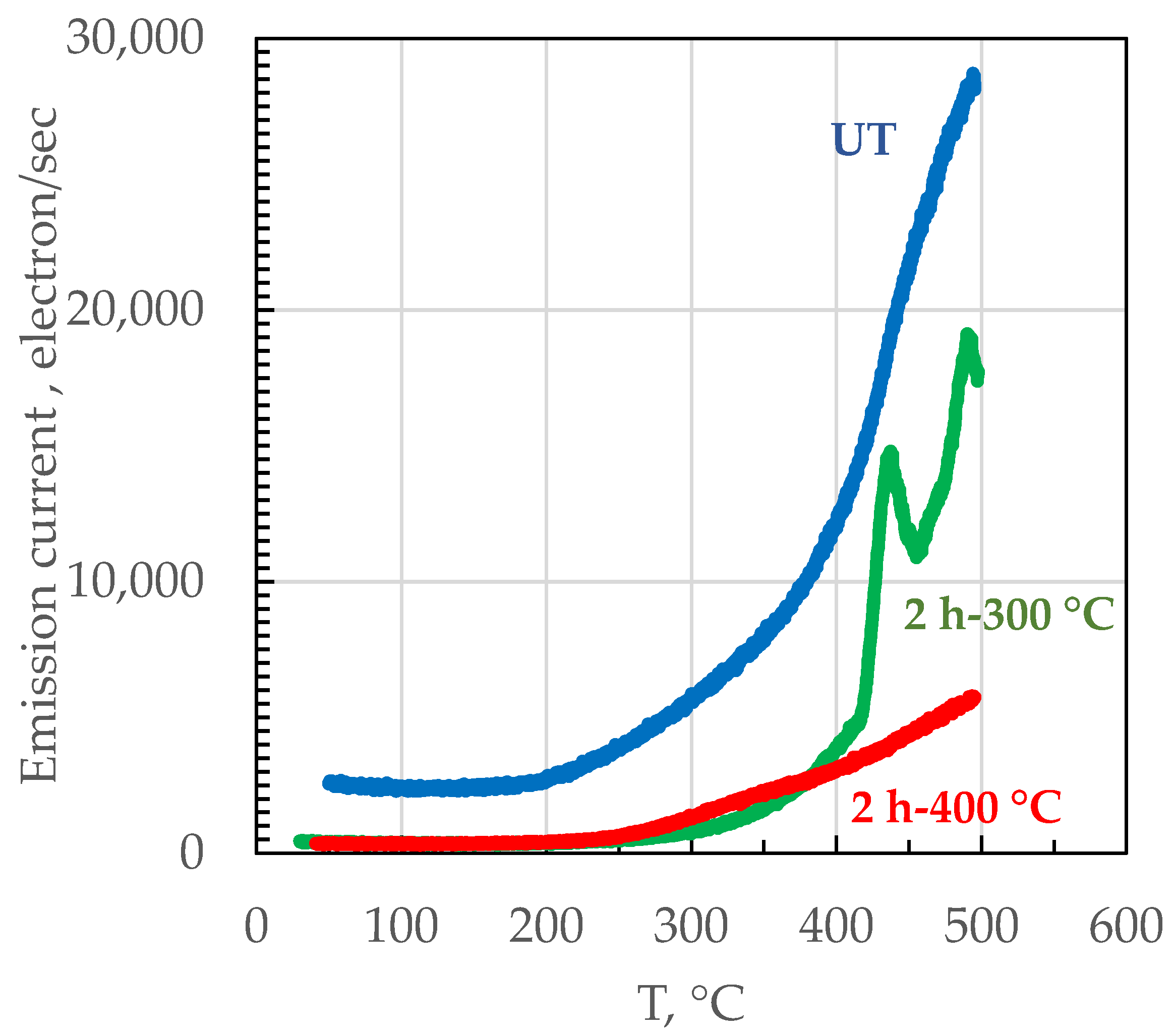
2.3. Exo-Electron Emission (EEE)
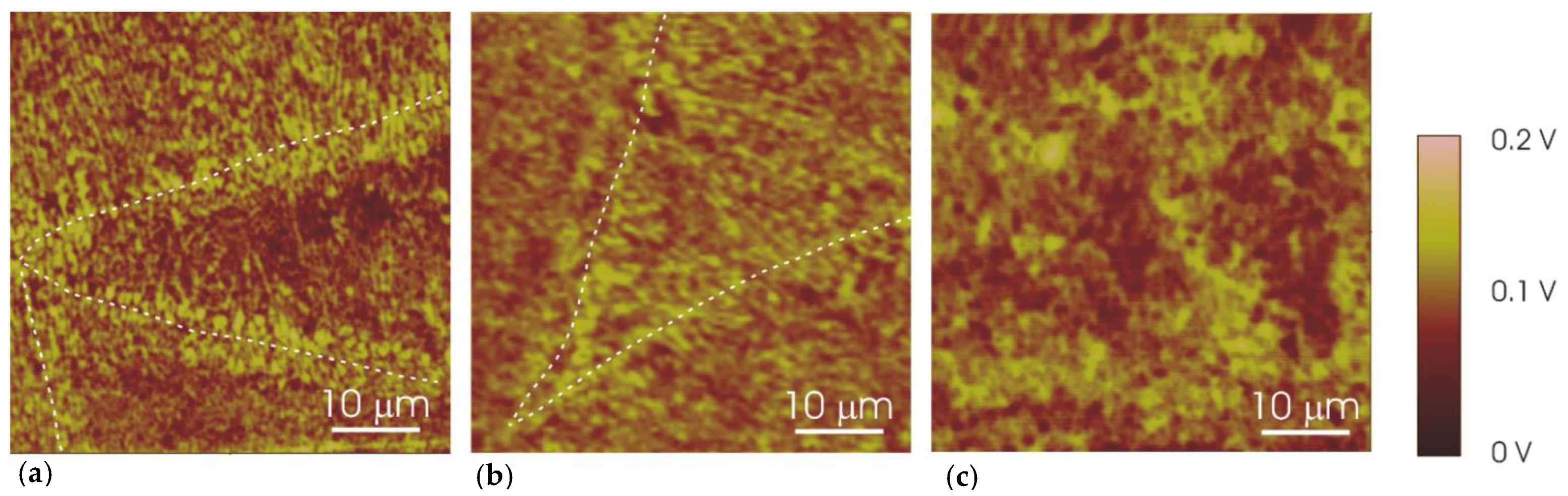
2.4. Scanning Kelvin Probe Force Microscope (SKPFM)
3. Results and Discussion
4. Conclusions
Author Contributions
Funding
Institutional Review Board Statement
Informed Consent Statement
Data Availability Statement
Conflicts of Interest
References
- Read, N.; Wang, W.; Essa, K.; Attallah, M.M. Selective laser melting of AlSi10Mg alloy: Process optimisation and mechanical properties development. Mater. Des. 2015, 65, 417–424. [Google Scholar] [CrossRef] [Green Version]
- Li, W.; Li, S.; Liu, J.; Zhang, A.; Zhou, Y.; Wei, Q.; Yan, C.; Shi, Y. Effect of heat treatment on AlSi10Mg alloy fabricated by selective laser melting: Microstructure evolution, mechanical properties and fracture mechanism. Mater. Sci. Eng. A 2016, 663, 116–125. [Google Scholar] [CrossRef]
- Kempen, K.; Thijs, L.; Van Humbeeck, J.; Kruth, J.P. Mechanical Properties of AlSi10Mg Produced by Selective Laser Melting. Phys. Procedia 2012, 39, 439–446. [Google Scholar] [CrossRef] [Green Version]
- Ye, H. An overview of the development of Al-Si-Alloy based material for engine applications. J. Mater. Eng. Perform. 2003, 12, 288–297. [Google Scholar] [CrossRef]
- Shakil, S.I.; Hadadzadeh, A.; Shalchi Amirkhiz, B.; Pirgazi, H.; Mohammadi, M.; Haghshenas, M. Additive manufactured versus cast AlSi10Mg alloy: Microstructure and micromechanics. Results Mater. 2021, 10, 100178. [Google Scholar] [CrossRef]
- Cabrini, M.; Lorenzi, S.; Pastore, T.; Testa, C.; Manfredi, D.; Cattano, G.; Calignano, F. Corrosion resistance in chloride solution of the AlSi10Mg alloy obtained by means of LPBF. Surf. Interface Anal. 2018, 51, 6–11. [Google Scholar] [CrossRef]
- Cabrini, M.; Calignano, F.; Fino, P.; Lorenzi, S.; Lorusso, M.; Manfredi, D.; Testa, C.; Pastore, T.; Id, D.M.; Testa, C.; et al. Corrosion Behavior of Heat-Treated AlSi10Mg Manufactured by Laser Powder Bed Fusion. Materials 2018, 11, 1051. [Google Scholar] [CrossRef] [Green Version]
- Cabrini, M.; Lorenzi, S.; Pastore, T.; Pellegrini, S.; Ambrosio, E.P.; Calignano, F.; Manfredi, D.; Pavese, M.; Fino, P. Effect of heat treatment on corrosion resistance of DMLS AlSi10Mg alloy. Electrochim. Acta 2016, 206, 346–355. [Google Scholar] [CrossRef]
- Fathi, P.; Mohammadi, M.; Duan, X.; Nasiri, A.M. A comparative study on corrosion and microstructure of direct metal laser sintered AlSi10Mg_200C and die cast A360.1 aluminum. J. Mater. Process. Technol. 2018, 259, 1–14. [Google Scholar] [CrossRef]
- Leon, A.; Shirizly, A.; Aghion, E. Corrosion Behavior of AlSi10Mg Alloy Produced by Additive Manufacturing (AM) vs. Its Counterpart Gravity Cast Alloy. Metals 2016, 6, 148. [Google Scholar] [CrossRef]
- Cabrini, M.; Lorenzi, S.; Pastore, T.; Pellegrini, S.; Manfredi, D.; Fino, P.; Biamino, S.; Badini, C. Evaluation of corrosion resistance of Al-10Si-Mg alloy obtained by means of Direct Metal Laser Sintering. J. Mater. Process. Technol. 2016, 231, 326–335. [Google Scholar] [CrossRef]
- Prashanth, K.G.; Debalina, B.; Wang, Z.; Gostin, P.F.; Gebert, A.; Calin, M.; Kühn, U.; Kamaraj, M.; Scudino, S.; Eckert, J. Tribological and corrosion properties of Al-12Si produced by selective laser melting. J. Mater. Res. 2014, 29, 2044–2054. [Google Scholar] [CrossRef]
- Rubben, T.; Revilla, R.I.; De Graeve, I. Influence of heat treatments on the corrosion mechanism of additive manufactured AlSi10Mg. Corros. Sci. 2019, 147, 406–415. [Google Scholar] [CrossRef]
- Takata, N.; Kodaira, H.; Sekizawa, K.; Suzuki, A.; Kobashi, M. Change in microstructure of selectively laser melted AlSi10Mg alloy with heat treatments. Mater. Sci. Eng. A 2017, 704, 218–228. [Google Scholar] [CrossRef]
- Revilla, R.I.; Liang, J.; Godet, S.; De Graeve, I. Local Corrosion Behavior of Additive Manufactured AlSiMg Alloy Assessed by SEM and SKPFM. J. Electrochem. Soc. 2017, 164, C27–C35. [Google Scholar] [CrossRef]
- Thuketana, S.; Taute, C.; Möller, H.; du Plessis, A. Characterization of surface roughness and subsurface pores and their effect on corrosion in 3D-printed AlSilOMg. J. South. African Inst. Min. Metall. 2020, 120, 369–376. [Google Scholar] [CrossRef]
- Fathi, P.; Mohammadi, M.; Nasiri, A.M. Low Surface Roughness Additively Manufactured AlSi10Mg: The Impacts on Corrosion and Water Repellency Properties. Miner. Met. Mater. Ser. 2020, 309–320. [Google Scholar] [CrossRef]
- Hamza, H.M.; Deen, K.M.; Khaliq, A.; Asselin, E.; Haider, W. Microstructural, corrosion and mechanical properties of additively manufactured alloys: A review. Crit. Rev. Solid State Mater. Sci. 2021, 1–53. [Google Scholar] [CrossRef]
- Brock, L.; Ogunsanya, I.; Asgari, H.; Patel, S.; Vlasea, M.; Brock, L.; Ogunsanya, I.; Asgari, H.; Patel, S.; Vlasea, M. Relative Performance of Additively Manufactured and Cast Aluminum Alloys. JMEP 2021, 30, 760–782. [Google Scholar] [CrossRef]
- Revilla, R.I.; Verkens, D.; Rubben, T.; De Graeve, I. Corrosion and corrosion protection of additively manufactured aluminium alloys—A critical review. Materials 2020, 13, 4804. [Google Scholar] [CrossRef]
- Revilla, R.I.; De Graeve, I. Influence of Si Content on the Microstructure and Corrosion Behavior of Additive Manufactured Al-Si Alloys. J. Electrochem. Soc. 2018, 165, C926–C932. [Google Scholar] [CrossRef]
- Cabrini, M.; Lorenzi, S.; Pastore, T.; Testa, C.; Manfredi, D.; Lorusso, M.; Calignano, F.; Pavese, M.; Andreatta, F. Corrosion behavior of AlSi10Mg alloy produced by laser powder bed fusion under chloride exposure. Corros. Sci. 2019, 152, 101–108. [Google Scholar] [CrossRef]
- Pezzato, L.; Dabala’, M.; Brunelli, K. Corrosion resistance of additive manufactured AlSi10Mg samples anodized or treated with PEO. LA Metall. Ital. 2020, 112, 18–23. [Google Scholar]
- Maeshima, T.; Oh-ishi, K. Solute clustering and supersaturated solid solution of AlSi10Mg alloy fabricated by selective laser melting. Heliyon 2019, 5, e01186. [Google Scholar] [CrossRef] [Green Version]
- Thijs, L.; Kempen, K.; Kruth, J.P.; Van Humbeeck, J. Fine-structured aluminium products with controllable texture by selective laser melting of pre-alloyed AlSi10Mg powder. Acta Mater. 2013, 61, 1809–1819. [Google Scholar] [CrossRef] [Green Version]
- Chen, H.; Zhang, C.; Jia, D.; Wellmann, D.; Liu, W. Corrosion behaviors of selective laser melted aluminum alloys: A review. Metals 2020, 10, 102. [Google Scholar] [CrossRef] [Green Version]
- Manfredi, D.; Calignano, F.; Krishnan, M.; Canali, R.; Ambrosio, E.P.; Atzeni, E. From powders to dense metal parts: Characterization of a commercial alsimg alloy processed through direct metal laser sintering. Materials 2013, 6, 856–869. [Google Scholar] [CrossRef] [Green Version]
- Rafieazad, M.; Mohammadi, M.; Nasiri, A.M. On microstructure and early stage corrosion performance of heat treated direct metal laser sintered AlSi10Mg. Addit. Manuf. 2019, 28, 107–119. [Google Scholar] [CrossRef]
- Sander, G.; Tan, J.; Balan, P.; Gharbi, O.; Feenstra, D.R.; Singer, L.; Thomas, S.; Kelly, R.G.; Scully, J.R.; Birbilis, N. Corrosion of additively manufactured alloys: A review. Corrosion 2018, 74, 1318–1350. [Google Scholar] [CrossRef] [Green Version]
- Cabrini, M.; Lorenzi, S.; Testa, C.; Pastore, T.; Manfredi, D.; Lorusso, M.; Calignano, F.; Fino, P. Statistical approach for electrochemical evaluation of the effect of heat treatments on the corrosion resistance of AlSi10Mg alloy by laser powder bed fusion. Electrochim. Acta 2019, 305, 459–466. [Google Scholar] [CrossRef]
- Yang, P.; Rodriguez, M.A.; Deibler, L.A.; Jared, B.H.; Griego, J.; Kilgo, A.; Allen, A.; Stefan, D.K. Effect of thermal annealing on microstructure evolution and mechanical behavior of an additive manufactured AlSi10Mg part. J. Mater. Res. 2018, 33, 1701–1712. [Google Scholar] [CrossRef] [Green Version]
- Brandl, E.; Heckenberger, U.; Holzinger, V.; Buchbinder, D. Additive manufactured AlSi10Mg samples using Selective Laser Melting (SLM): Microstructure, high cycle fatigue, and fracture behavior. Mater. Des. 2012, 34, 159–169. [Google Scholar] [CrossRef]
- Zeng, F.L.; Wei, Z.L.; Li, J.F.; Li, C.X.; Tan, X.; Zhang, Z.; Zheng, Z.Q. Corrosion mechanism associated with Mg 2Si and Si particles in Al-Mg-Si alloys. Trans. Nonferrous Met. Soc. China English Ed. 2011, 21, 2559–2567. [Google Scholar] [CrossRef]
- Gupta, R.K.; Sukiman, N.L.; Fleming, K.M.; Gibson, M.A.; Birbilis, N. Electrochemical behavior and localized corrosion associated with Mg2Si particles in Al and Mg alloys. ECS Electrochem. Lett. 2012, 1, C1. [Google Scholar] [CrossRef]
- Marola, S.; Manfredi, D.; Fiore, G.; Poletti, M.G.; Lombardi, M.; Fino, P.; Battezzati, L. A comparison of Selective Laser Melting with bulk rapid solidification of AlSi10Mg alloy. J. Alloys Compd. 2018, 742, 271–279. [Google Scholar] [CrossRef]
- Gu, X.; Zhang, J.; Fan, X.; Dai, N.; Xiao, Y.; Zhang, L.C. Abnormal corrosion behavior of selective laser melted AlSi10Mg alloy induced by heat treatment at 300 °C. J. Alloys Compd. 2019, 803, 314–324. [Google Scholar] [CrossRef]
- Scharmann, A. Keynote paper on exoelectron emission research. Jpn. J. Appl. Phys. 1985, 24, 6–10. [Google Scholar] [CrossRef]
- Klar, F.; Bansmann, J.; Glaefeke, H.; Fitting, H.J.; Meiwes-Broer, K.H. Exoelectron emission from magnesium surfaces. Surf. Sci. 1999, 442, 477–484. [Google Scholar] [CrossRef]
- Himmel, L. Exo-electron Emission from Metals. In Proceedings of the Interdisciplinary Workshop for Quantitative Flaw Definition, New York, NY, USA, 21 June 1974. [Google Scholar]
- Górecki, T.; Górecki, C. Exoelectron emission accompanying phase changes in age-hardenable aluminium alloys. Jpn. J. Appl. Phys. 1985, 24, 102–105. [Google Scholar] [CrossRef]
- Górecki, T. Exoelectron Emission During Phase Transformations in Metallic Materials. Rev. Latinoam. Metal. Mater. 1987, 7, 3–17. [Google Scholar]
- Sujak, B.; Górecki, T.; Malkiewicz, M.; Stepriowski, I. No Title. Acta Phys. Pol. 1966, 30, 51. [Google Scholar]
- Melitz, W.; Shen, J.; Kummel, A.C.; Lee, S. Kelvin probe force microscopy and its application. Surf. Sci. Rep. 2011, 66, 1–27. [Google Scholar] [CrossRef]
- Calignano, F.; Manfredi, D.; Ambrosio, E.P.; Iuliano, L.; Fino, P. Influence of process parameters on surface roughness of aluminum parts produced by DMLS. Int. J. Adv. Manuf. Technol. 2013, 67, 2743–2751. [Google Scholar] [CrossRef] [Green Version]
- Manfredi, D.; Calignano, F.; Ambrosio, E.P.; Krishnan, M.; Canali, R.; Biamino, S.; Pavese, M.; Atzeni, E.; Luliano, L.; Fino, P.; et al. Direct Metal Laser Sintering: An additive manufacturing technology ready to produce lightweight structural parts for robotic applications. Metall. Ital. 2013, 105, 15–24. [Google Scholar] [CrossRef]
- Romanova, M.; Burve, R.; Cichon, S.; Dekhtyar, Y.; Fekete, L.; Jevdokimovs, D.; Krumina, A.; Palskis, K.; Serga, V. Effect of gamma radiation on thermostimulated exoelectron emission from Gd2O3 films. Nucl. Instruments Methods Phys. Res. Sect. B Beam Interact. Mater. Atoms 2020, 463, 21–26. [Google Scholar] [CrossRef]


| Element | Si | Fe | Cu | Mn | Mg | Ni | Zn | Ti | Al |
|---|---|---|---|---|---|---|---|---|---|
| % weight | 9–11 | ≤0.55 | ≤0.05 | ≤0.45 | 0.2–0.45 | ≤0.05 | ≤0.1 | ≤0.15 | bulk |
| Spectrum Label | Spectrum 8 | Spectrum 9 | Spectrum 10 |
|---|---|---|---|
| Mg | 0.3 | 0.5 | 0.4 |
| Al | 93.2 | 58.5 | 89.5 |
| Si | 5.5 | 40.5 | 10.1 |
| Fe | - | 0.5 | - |
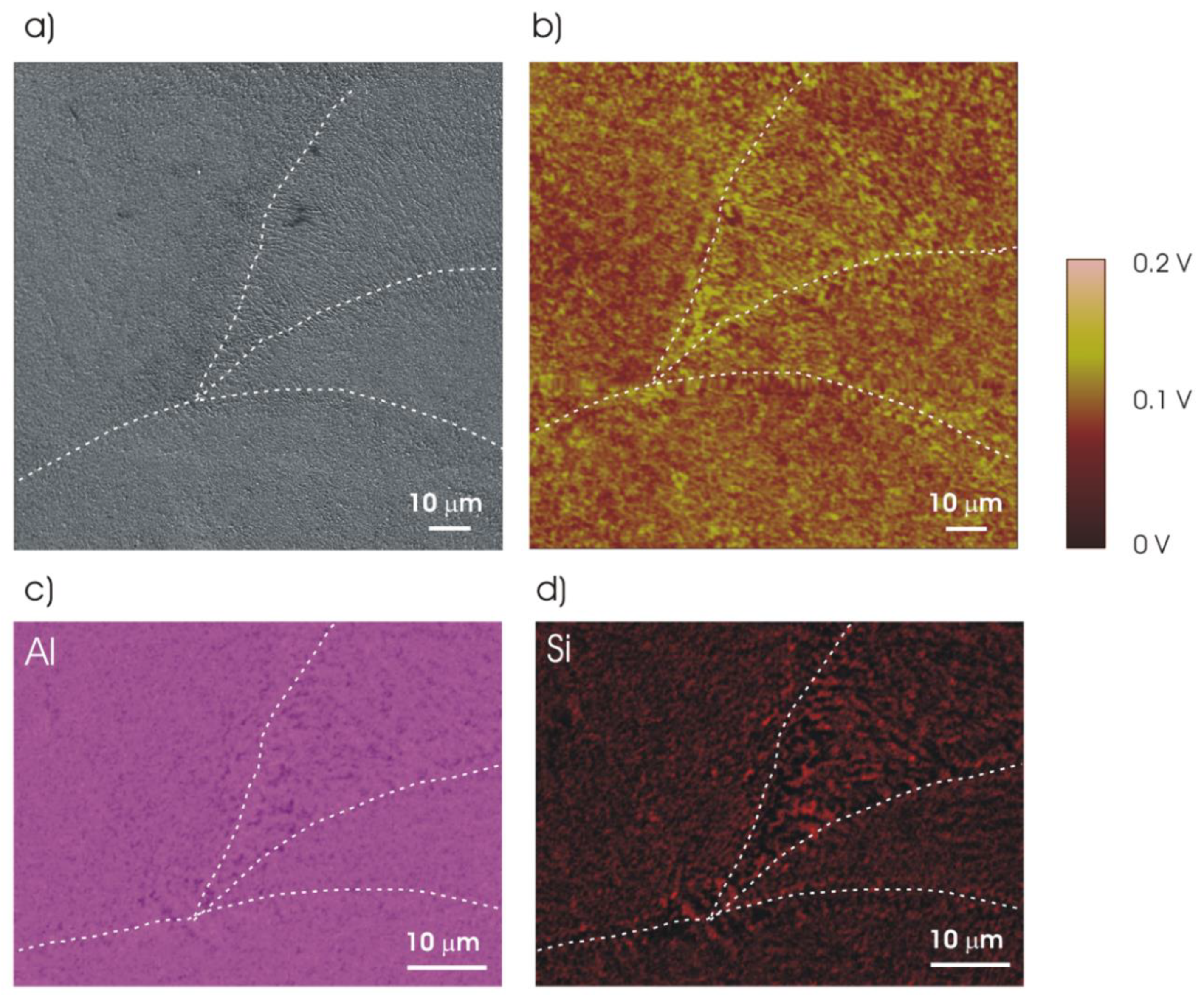
| Specimen | Edge of the Melt Pool [mV] | Centre of the Melt Pool [mV] |
|---|---|---|
| UT | 133 ± 9 | 88 ± 6 |
| 2h-300 | 94 ± 8 | 60 ± 6 |
| 2h-400 | 86 ± 10 | |
Publisher’s Note: MDPI stays neutral with regard to jurisdictional claims in published maps and institutional affiliations. |
© 2021 by the authors. Licensee MDPI, Basel, Switzerland. This article is an open access article distributed under the terms and conditions of the Creative Commons Attribution (CC BY) license (https://creativecommons.org/licenses/by/4.0/).
Share and Cite
Cabrini, M.; Lorenzi, S.; Testa, C.; Manfredi, D.; Lombardi, M.; Aversa, A.; Andreatta, F.; Fedrizzi, L.; Dekhtyar, Y.; Sorokins, H.; et al. Effect of Heat Treatment on Microstructure and Selective Corrosion of LPBF-AlSi10Mg by Means of SKPFM and Exo-Electron Emission. Materials 2021, 14, 5602. https://doi.org/10.3390/ma14195602
Cabrini M, Lorenzi S, Testa C, Manfredi D, Lombardi M, Aversa A, Andreatta F, Fedrizzi L, Dekhtyar Y, Sorokins H, et al. Effect of Heat Treatment on Microstructure and Selective Corrosion of LPBF-AlSi10Mg by Means of SKPFM and Exo-Electron Emission. Materials. 2021; 14(19):5602. https://doi.org/10.3390/ma14195602
Chicago/Turabian StyleCabrini, Marina, Sergio Lorenzi, Cristian Testa, Diego Manfredi, Mariangela Lombardi, Alberta Aversa, Francesco Andreatta, Lorenzo Fedrizzi, Yuri Dekhtyar, Hermanis Sorokins, and et al. 2021. "Effect of Heat Treatment on Microstructure and Selective Corrosion of LPBF-AlSi10Mg by Means of SKPFM and Exo-Electron Emission" Materials 14, no. 19: 5602. https://doi.org/10.3390/ma14195602
APA StyleCabrini, M., Lorenzi, S., Testa, C., Manfredi, D., Lombardi, M., Aversa, A., Andreatta, F., Fedrizzi, L., Dekhtyar, Y., Sorokins, H., & Pastore, T. (2021). Effect of Heat Treatment on Microstructure and Selective Corrosion of LPBF-AlSi10Mg by Means of SKPFM and Exo-Electron Emission. Materials, 14(19), 5602. https://doi.org/10.3390/ma14195602