
Bioinspired Helicoidal Composite Structure Featuring Functionally Graded Variable Ply Pitch


Abstract
:1. Literature Review
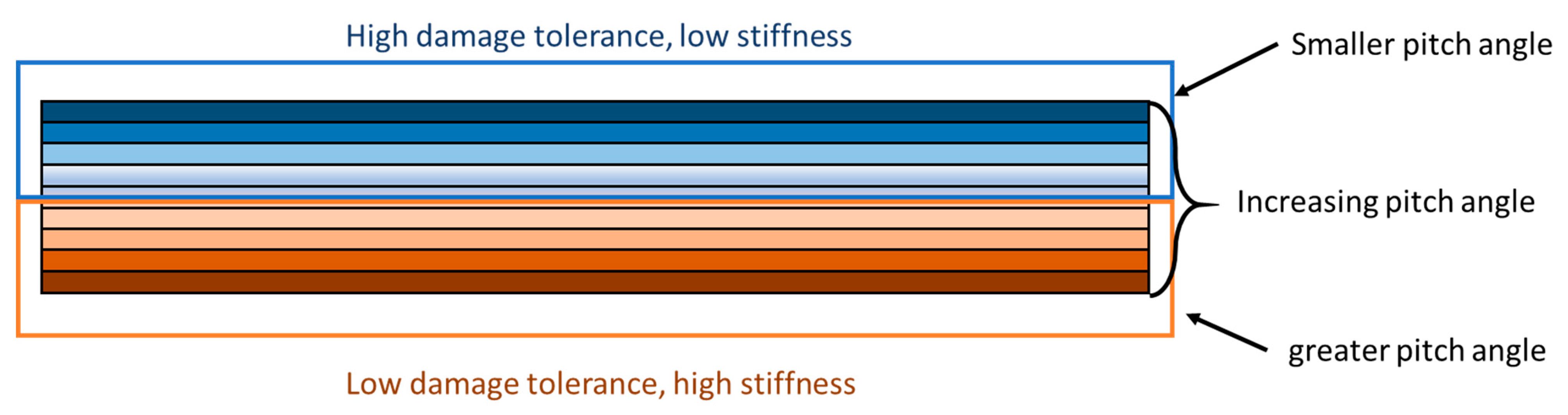
2. Functionally Graded Pitch (FGP) Laminates
2.1. Mechanical Performance
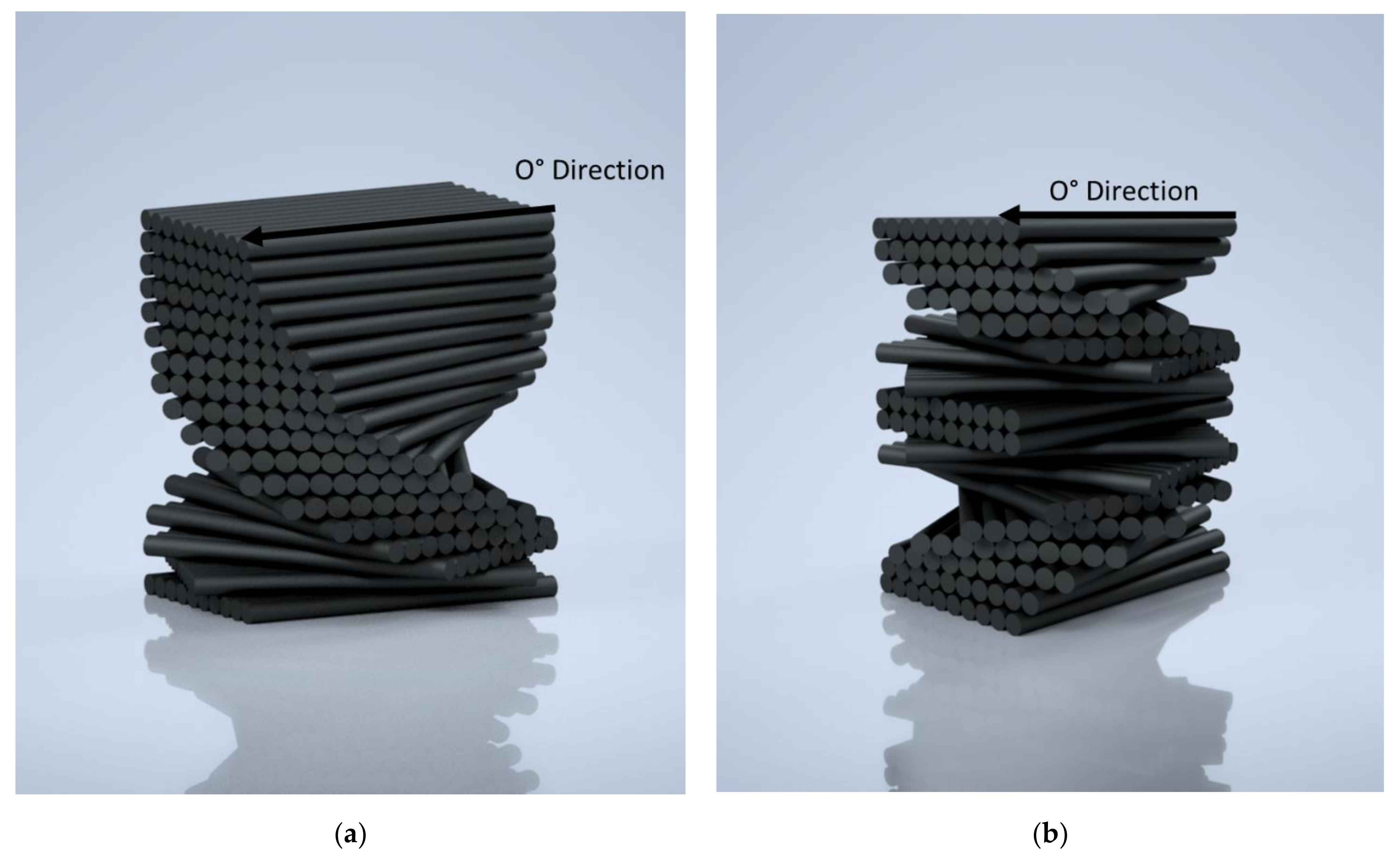
2.2. Design Description
3. Materials and Methods
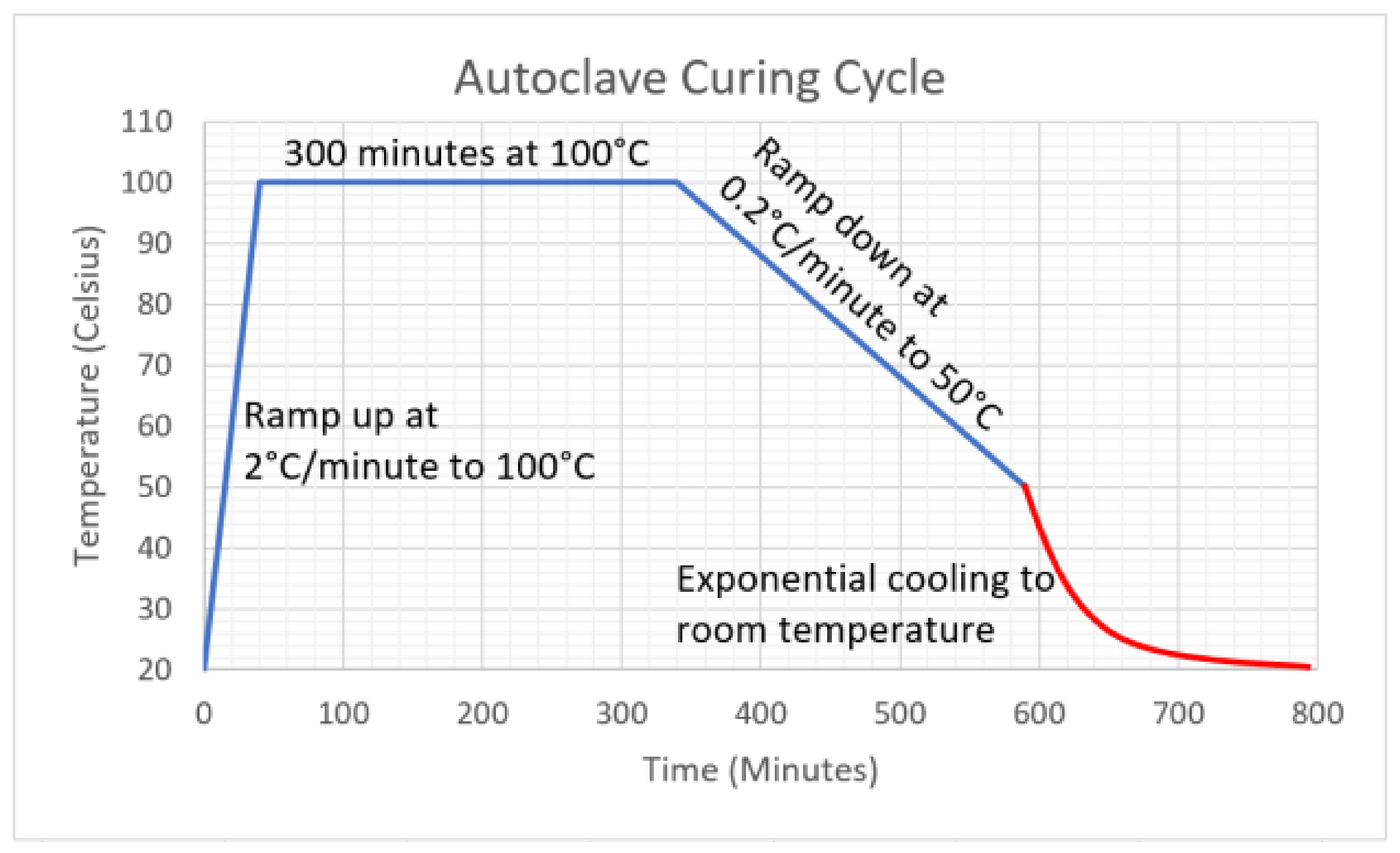
3.1. Sample Manufacturing
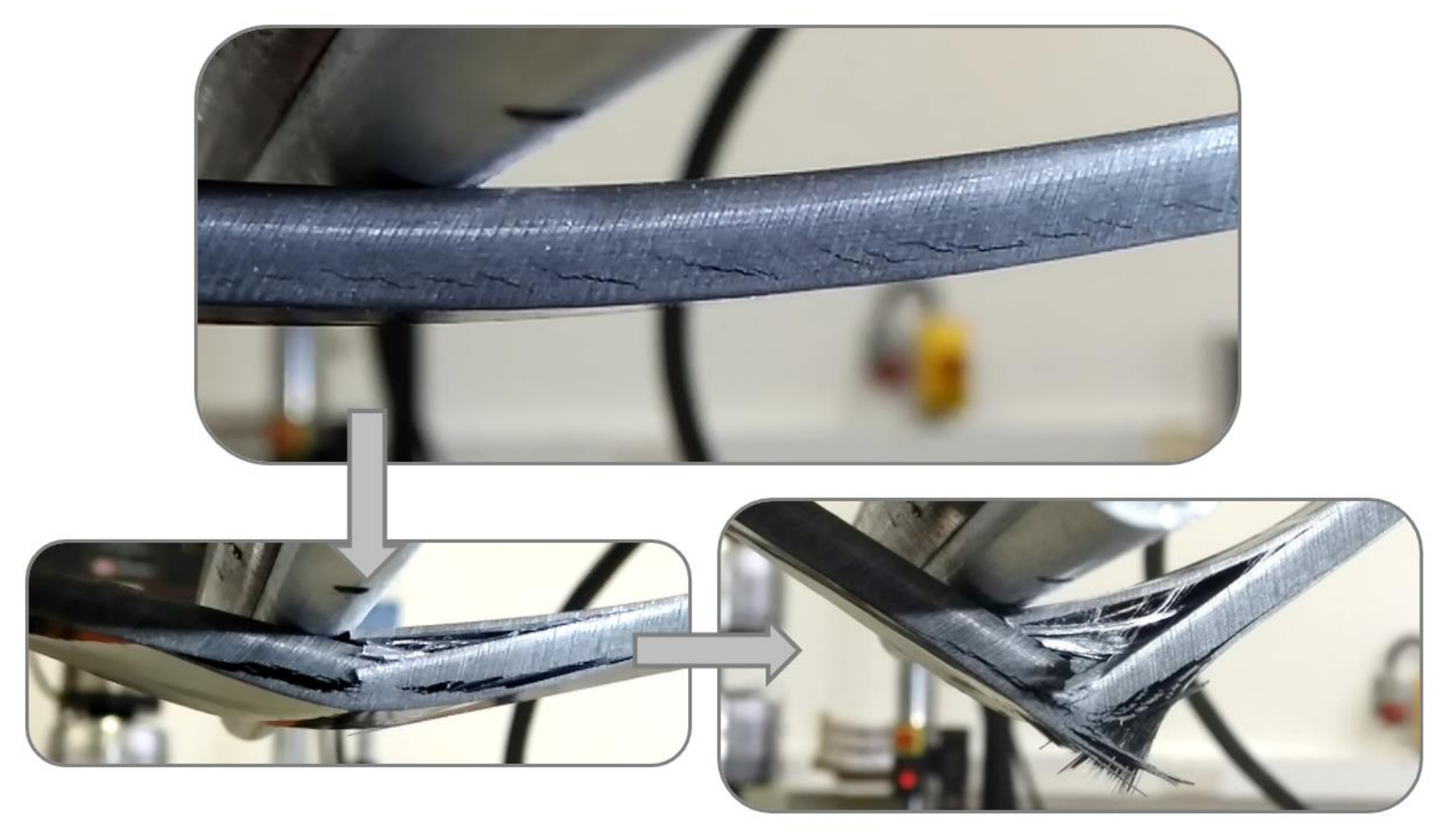
3.2. Three-Point Bending
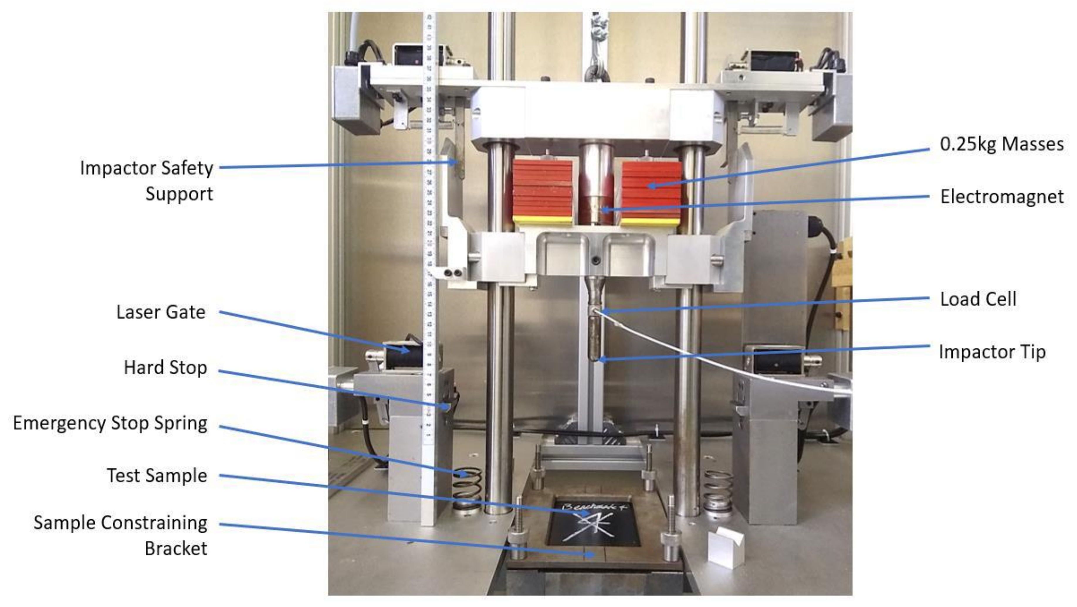
3.3. Low Velocity Impact
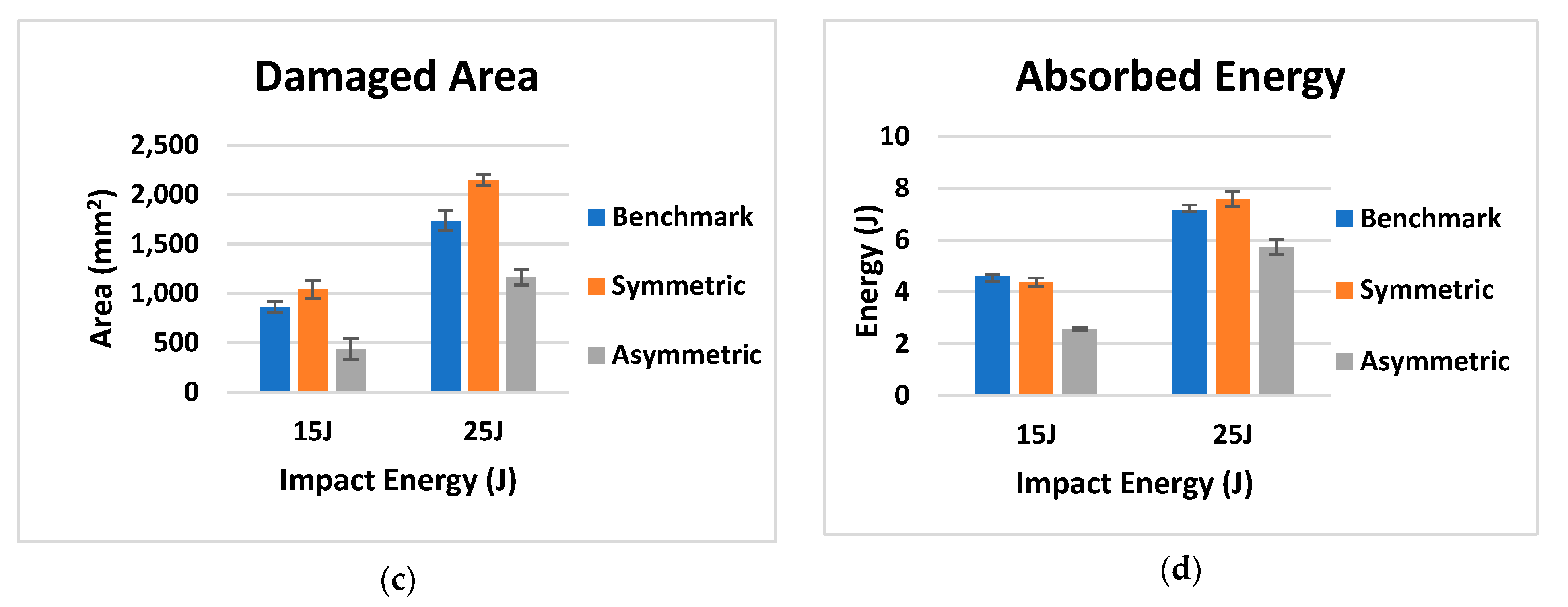
4. Results and Discussion
4.1. Flexural Tests
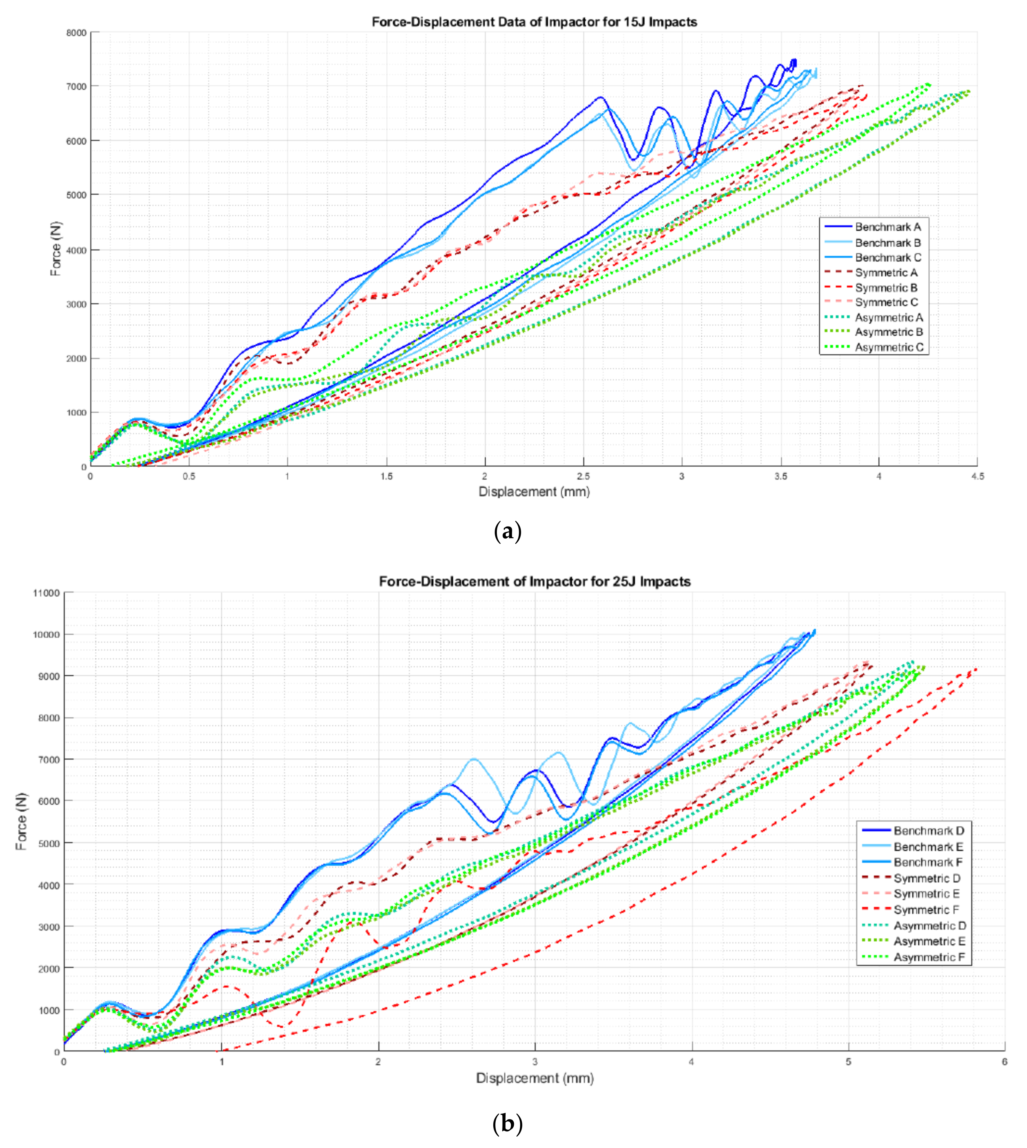
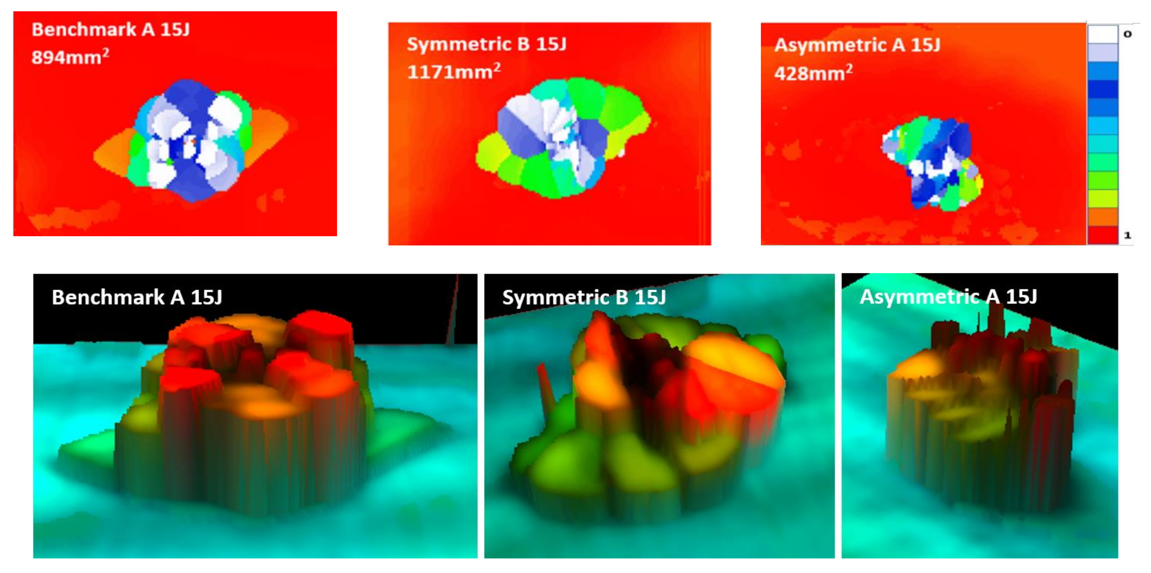
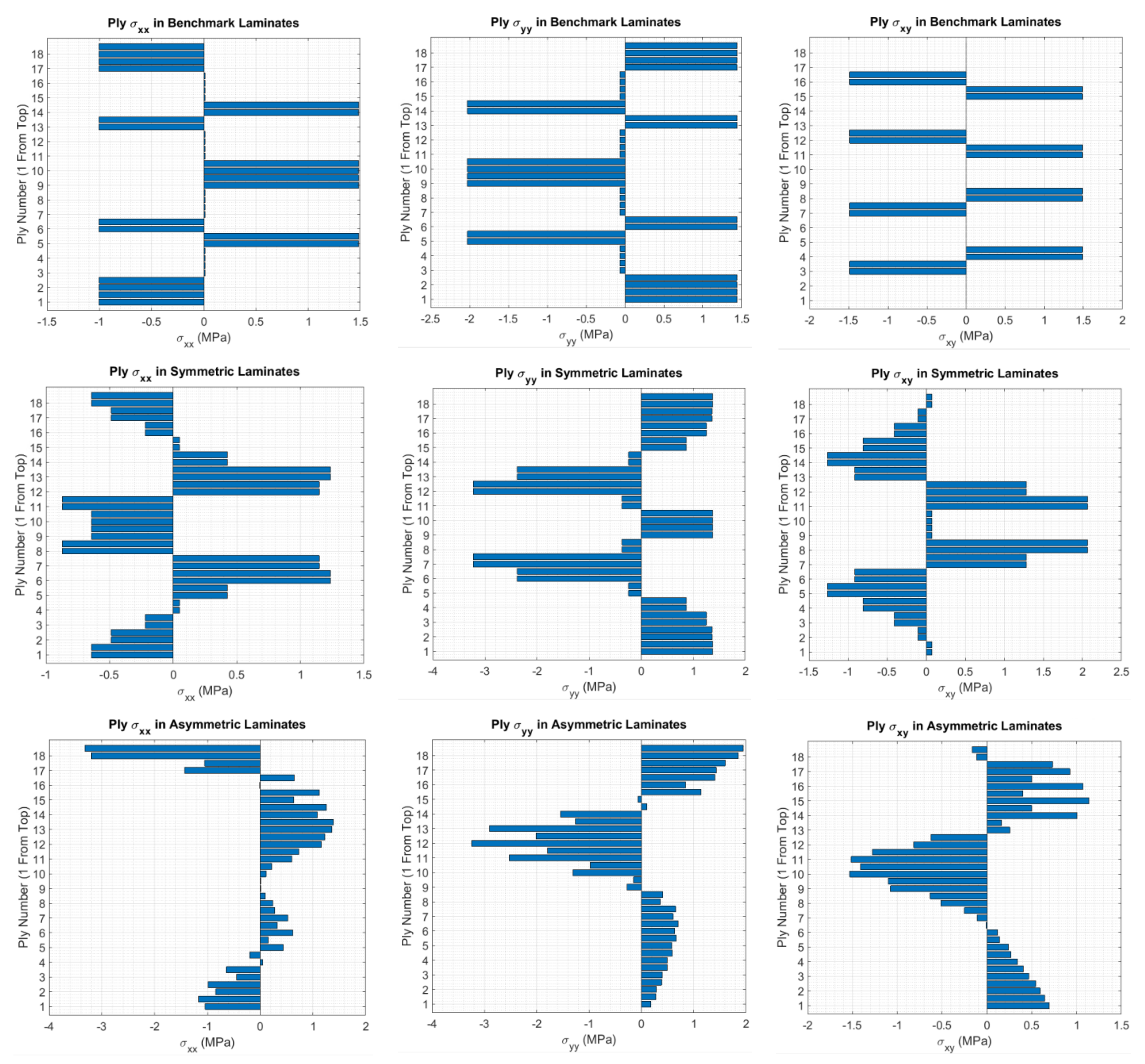
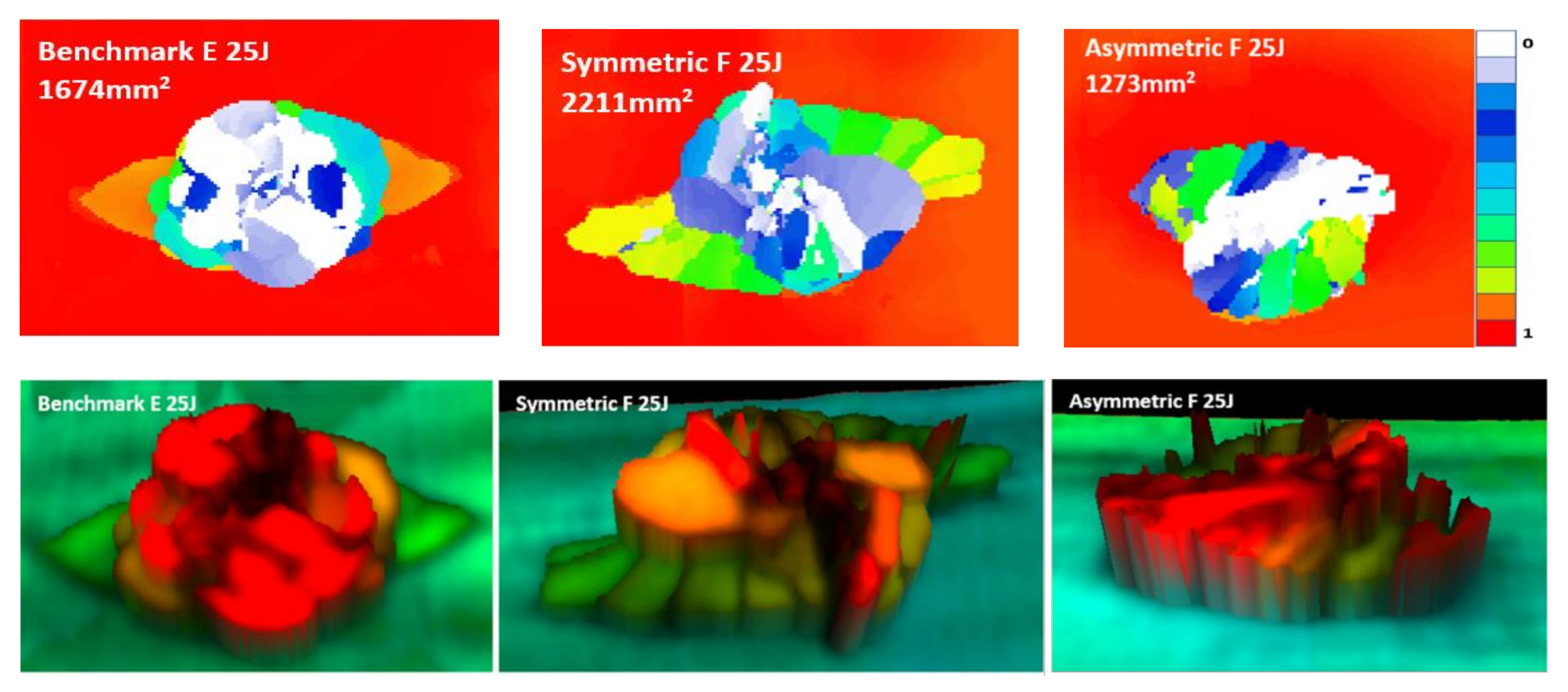
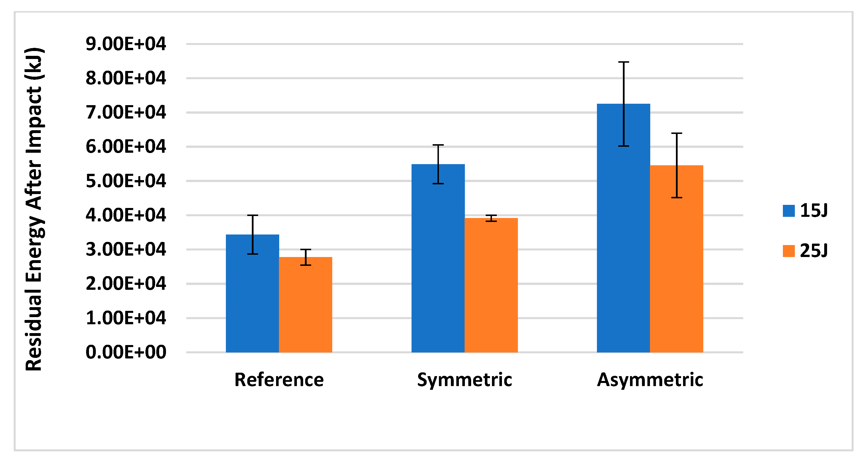
4.2. Impact Tests
5. Conclusions
Author Contributions
Funding
Institutional Review Board Statement
Informed Consent Statement
Data Availability Statement
Conflicts of Interest
Appendix A. Thermal Warpage

| Benchmark | |
|---|---|
| [A] Matrix: | kN/mm |
| [B] Matrix: | kN |
| [D] Matrix: | kNmm |
| Functionally Graded Helicoidal Symmetric | |
| [A] Matrix: | kN/mm |
| [B] Matrix: | kN |
| [D] Matrix: | kNmm |
| Functionally Graded Helicoidal Asymmetric | |
| [A] Matrix: | kN/mm |
| [B] Matrix: | kN |
| [D] Matrix: | kNmm |
References
- Abrate, S. Impact on laminated composite materials. Appl. Mech. Rev. 1991, 44, 155–190. [Google Scholar] [CrossRef]
- Russell, A.I.; Street, K.N. The effect of matrix toughness on delamination: Static and fatigue fracture under mode II shear loading of graphite fiber composites. In Toughened Composites; Johnston, N.J., Ed.; ASTM International: West Conshohocken, PA, USA, 2008; p. 275. [Google Scholar]
- Ning, J.; Zhang, J.; Pan, Y.; Guo, J. Fabrication and mechanical properties of SiO2 matrix composites reinforced by carbon nanotube. Mater. Sci. Eng. A 2003, 357, 392–396. [Google Scholar] [CrossRef]
- Cho, J.; Chen, J.; Daniel, I. Mechanical enhancement of carbon fiber/epoxy composites by graphite nanoplatelet reinforcement. Scr. Mater. 2007, 56, 685–688. [Google Scholar] [CrossRef]
- Rizzo, F.; Pinto, F.; Meo, M. Development of multifunctional hybrid metal/carbon composite structures. Compos. Struct. 2019, 222, 110907. [Google Scholar] [CrossRef]
- Rizzo, F.; Pinto, F.; Meo, M. Investigation of silica-based shear thickening fluid in enhancing composite impact resistance. Appl. Compos. Mater. 2020, 27, 209–229. [Google Scholar] [CrossRef]
- Rizzo, F.; Cuomo, S.; Pinto, F.; Pucillo, G.; Meo, M. Thermoplastic polyurethane composites for railway applications: Experimental and numerical study of hybrid laminates with improved impact resistance. J. Thermoplast. Compos. Mater. 2019. [Google Scholar] [CrossRef]
- Heinemann, F.; Launspach, M.; Gries, K.; Fritz, M. Gastropod nacre: Structure, properties and growth—Biological, chemical and physical basics. Biophys. Chem. 2011, 153, 126–153. [Google Scholar] [CrossRef]
- Zaheri, A.; Fenner, J.S.; Russell, B.P.; Restrepo, D.; Daly, M.; Wang, D.; Hayashi, C.; Meyers, M.A.; Zavattieri, P.D.; Espinosa, H.D. Revealing the mechanics of helicoidal composites through additive manufacturing and beetle developmental stage analysis. Adv. Funct. Mater. 2018, 28. [Google Scholar] [CrossRef]
- Suksangpanya, N.; Yaraghi, N.A.; Kisailus, D.; Zavattieri, P. Twisting cracks in Bouligand structures. J. Mech. Behav. Biomed. Mater. 2017, 76, 38–57. [Google Scholar] [CrossRef]
- Sun, J.; Bhushan, B. Hierarchical structure and mechanical properties of nacre: A review. RSC Adv. 2012, 2, 7617–7632. [Google Scholar] [CrossRef]
- Rizzo, F.; Pinto, F.; Meo, M. 3D bio-inspired hierarchical discontinuous CFRP with enhanced ductility. Compos. Struct. 2019, 226, 111202. [Google Scholar] [CrossRef]
- Zimmermann, E.; Gludovatz, B.; Schaible, E.; Dave, N.K.N.; Yang, W.; Meyers, M.; Ritchie, R.O. Mechanical adaptability of the Bouligand-type structure in natural dermal armour. Nat. Commun. 2013, 4, 2634. [Google Scholar] [CrossRef] [PubMed] [Green Version]
- Cheng, L.; Wang, L.; Karlsson, A.M. Mechanics-based analysis of selected features of the exoskeletal microstructure of Popillia japonica. J. Mater. Res. 2009, 24, 3253–3267. [Google Scholar] [CrossRef] [Green Version]
- Vincent, J.F. Arthropod cuticle: A natural composite shell system. Compos. Part A Appl. Sci. Manuf. 2002, 33, 1311–1315. [Google Scholar] [CrossRef]
- Mencattelli, L.; Pinho, S.T. Realising bio-inspired impact damage-tolerant thin-ply CFRP Bouligand structures via promoting diffused sub-critical helicoidal damage. Compos. Sci. Technol. 2019, 182, 107684. [Google Scholar] [CrossRef]
- Suksangpanya, N.; Yaraghi, N.A.; Pipes, R.B.; Kisailus, D.; Zavattieri, P. Crack twisting and toughening strategies in Bouligand architectures. Int. J. Solids Struct. 2018, 150, 83–106. [Google Scholar] [CrossRef]
- Shang, J.; Ngern, N.H.; Tan, V.B. Crustacean-inspired helicoidal laminates. Compos. Sci. Technol. 2016, 128, 222–232. [Google Scholar] [CrossRef]
- Ginzburg, D.; Pinto, F.; Iervolino, O.; Meo, M. Damage tolerance of bio-inspired helicoidal composites under low velocity impact. Compos. Struct. 2017, 161, 187–203. [Google Scholar] [CrossRef] [Green Version]
- Grunenfelder, L.; Suksangpanya, N.; Salinas, C.; Milliron, G.; Yaraghi, N.; Herrera, S.; Evans-Lutterodt, K.; Nutt, S.; Zavattieri, P.; Kisailus, D. Bio-inspired impact-resistant composites. Acta Biomater. 2014, 10, 3997–4008. [Google Scholar] [CrossRef]
- Mahamood, R.M.; Akinlabi, E.T.; Shukla, M.; Pityana, S. Functionally graded material: An overview. In Proceedings of the World Congress on Engineering 2012 (WCE 2012), London, UK, 4–6 July 2012. [Google Scholar]
- Pagang, N.J.; Hatfield, S.J.; Pagano, N.; Hatfield, H.J. Elastic behavior of multilayered bidirectional composites. AIAA J. 1972, 10, 931–933. [Google Scholar] [CrossRef]
- Erdogan, F. Fracture mechanics of functionally graded materials. Compos. Eng. 1995, 5, 753–770. [Google Scholar] [CrossRef]
- Gu, P.; Asaro, R. Cracks in functionally graded materials. Int. J. Solids Struct. 1997, 34, 1–17. [Google Scholar] [CrossRef]
- Bao, G.; Cai, H. Delamination cracking in functionally graded coating/metal substrate systems. Acta Mater. 1997, 45, 1055–1066. [Google Scholar] [CrossRef]
- Liu, Z.; Meyers, M.A.; Zhang, Z.; Ritchie, R.O. Functional gradients and heterogeneities in biological materials: Design principles, functions, and bioinspired applications. Prog. Mater. Sci. 2017, 88, 467–498. [Google Scholar] [CrossRef]
- Sola, A.; Bellucci, D.; Cannillo, V. Functionally graded materials for orthopedic applications—An update on design and manufacturing. Biotechnol. Adv. 2016, 34, 504–531. [Google Scholar] [CrossRef] [PubMed]
- Sun, C.-Y.; Chen, P.-Y. Structural design and mechanical behavior of alligator (Alligator mississippiensis) osteoderms. Acta Biomater. 2013, 9, 9049–9064. [Google Scholar] [CrossRef] [PubMed]
- Degtyar, E.; Harrington, M.J.; Politi, Y.; Fratzl, P. The mechanical role of metal ions in biogenic protein-based materials. Angew. Chem. Int. Ed. 2014, 53, 12026–12044. [Google Scholar] [CrossRef]
- Peisker, H.; Michels, J.; Gorb, S.N. Evidence for a material gradient in the adhesive tarsal setae of the ladybird beetle Coccinella septempunctata. Nat. Commun. 2013, 4, 1661. [Google Scholar] [CrossRef] [PubMed] [Green Version]
- Chen, I.H.; Yang, W.; Meyers, M. Alligator osteoderms: Mechanical behavior and hierarchical structure. Mater. Sci. Eng. C 2014, 35, 441–448. [Google Scholar] [CrossRef]
- Raabe, D.; Sachs, C.; Romano, P. The crustacean exoskeleton as an example of a structurally and mechanically graded biological nanocomposite material. Acta Mater. 2005, 53, 4281–4292. [Google Scholar] [CrossRef]
- Chen, P.-Y.; Lin, A.Y.-M.; McKittrick, J.; Meyers, M. Structure and mechanical properties of crab exoskeletons. Acta Biomater. 2008, 4, 587–596. [Google Scholar] [CrossRef] [PubMed]
- Liu, Z.; Jiao, D.; Weng, Z.; Zhang, Z. Structure and mechanical behaviors of protective armored pangolin scales and effects of hydration and orientation. J. Mech. Behav. Biomed. Mater. 2016, 56, 165–174. [Google Scholar] [CrossRef]
- Wang, B.; Yang, W.; Sherman, V.R.; Meyers, M.A. Pangolin armor: Overlapping, structure, and mechanical properties of the keratinous scales. Acta Biomater. 2016, 41, 60–74. [Google Scholar] [CrossRef]
- Friedrich, K. Application of Fracture Mechanics to Composite Materials; Elsevier: Amsterdam, The Netherlands, 2012. [Google Scholar]
- Liu, J.L.; Lee, H.; Tan, V. Failure mechanisms in bioinspired helicoidal laminates. Compos. Sci. Technol. 2018, 157, 99–106. [Google Scholar] [CrossRef]
- Andersons, J.; König, M. Dependence of fracture toughness of composite laminates on interface ply orientations and delamination growth direction. Compos. Sci. Technol. 2004, 64, 2139–2152. [Google Scholar] [CrossRef]
- Tao, J.; Sun, C.T. Influence of ply orientation on delamination in composite laminates. J. Compos. Mater. 1998, 32, 1933–1947. [Google Scholar] [CrossRef]
- Kim, B.W.; Mayer, A.H. Influence of fiber direction and mixed-mode ratio on delamination fracture toughness of carbon/epoxy laminates. Compos. Sci. Technol. 2003, 63, 695–713. [Google Scholar] [CrossRef]
- Riccio, A.; Linde, P.; Raimondo, A.; Buompane, A.; Sellitto, A. On the use of selective stitching in stiffened composite panels to prevent skin-stringer debonding. Compos. Part. B Eng. 2017, 124, 64–75. [Google Scholar] [CrossRef]
- Sellitto, A.; Saputo, S.; Di Caprio, F.; Riccio, A.; Russo, A.; Acanfora, V. Numerical-experimental correlation of impact-induced damages in CFRP laminates. Appl. Sci. 2019, 9, 2372. [Google Scholar] [CrossRef] [Green Version]
- Riccio, A.; Russo, A.; Sellitto, A.; Toscano, C.; Alfano, D.; Zarrelli, M. Experimental and numerical assessment of fibre bridging toughening effects on the compressive behaviour of delaminated composite plates. Polymers 2020, 12, 554. [Google Scholar] [CrossRef] [Green Version]
- Liu, J.L.; Lee, H.; Tan, V. Effects of inter-ply angles on the failure mechanisms in bioinspired helicoidal laminates. Compos. Sci. Technol. 2018, 165, 282–289. [Google Scholar] [CrossRef]
- Abrate, S. Impact Dynamics. Impact Engineering of Composite Structures; Springer: Berlin, Germany, 2011; pp. 71–96. [Google Scholar]
- Vasiliev, V.V.; Morozov, E.V. Chapter 3—Mechanics of laminates. In Advanced Mechanics of Composite Materials and Structures, 4th ed.; Vasiliev, V.V., Morozov, E.V., Eds.; Elsevier: Amsterdam, The Netherlands, 2018; pp. 191–242. [Google Scholar]
- Weaver, J.C.; Milliron, G.W.; Miserez, A.; Evans-Lutterodt, K.; Herrera, S.; Gallana, I.; Mershon, W.J.; Swanson, B.; Zavattieri, P.; DiMasi, E.; et al. The stomatopod dactyl club: A formidable damage-tolerant biological hammer. Science 2012, 336, 1275–1280. [Google Scholar] [CrossRef] [Green Version]
- Cheng, L.; Wang, L.; Karlsson, A.M. Image analyses of two crustacean exoskeletons and implications of the exoskeletal microstructure on the mechanical behavior. J. Mater. Res. 2008, 23, 2854–2872. [Google Scholar] [CrossRef] [Green Version]
- Radford, D.; Rennick, T. Separating sources of manufacturing distortion in laminated composites. J. Reinf. Plast. Compos. 2000, 19, 621–641. [Google Scholar] [CrossRef]
- Swanson, S.R. Limits of quasi-static solutions in impact of composite structures. Compos. Eng. 1992, 2, 261–267. [Google Scholar] [CrossRef]
- Sun, C.T.; Chin, H. Analysis of asymmetric composite laminates. AIAA J. 1988, 26, 714–718. [Google Scholar] [CrossRef]
- Santiuste, C.; Sanchez-Saez, S.; Barbero, E. Residual flexural strength after low-velocity impact in glass/polyester composite beams. Compos. Struct. 2010, 92, 25–30. [Google Scholar] [CrossRef] [Green Version]
- Zhang, Z.; Richardson, M. Low velocity impact induced damage evaluation and its effect on the residual flexural properties of pultruded GRP composites. Compos. Struct. 2007, 81, 195–201. [Google Scholar] [CrossRef]
- Apichattrabrut, T.; Ravi-Chandar, K. Helicoidal composites. Mech. Adv. Mater. Struct. 2006, 13, 61–76. [Google Scholar] [CrossRef]
- Iyer, H. The Effects of Shear Deformation in Rectangular and Wide Flange Sections. PhD. Thesis, Virginia Tech, Blacksburg, VA, USA, 2005. [Google Scholar]
- Anderson, T.L. Fracture Mechanics: Fundamentals and Applications; CRC Press: Boca Raton, FL, USA, 2017. [Google Scholar]
- Jones, R.M. Mechanics of Composite Materials; CRC Press: Boca Raton, FL, USA, 2014. [Google Scholar]


| Lay-Up Title | Ply Structure |
|---|---|
| Benchmark | [0/0/+45/−45/90/0/+45/−45/90]s |
| FGPS (c = 1.2) | [0/5/15/30/50/75/105/140/180]s |
| FGPA (c = 5) | [0/1.2/3.5/7.1/11.8/17.7/24.7/32.9/42.4/52.9/64.7/77.6/91.8/107.1/123.5/141.2/160/180] |
| Design | Flexural Modulus (GPa) | % Variation | Flexural Strength (MPa) | % Variation | Flexural Strain (Maximum Load) | % Variation | SEE (kJ/m3) | % Variation |
|---|---|---|---|---|---|---|---|---|
| Benchmark | 79.2 ± 2.32 | - | 842 ± 19.56 | - | 0.0109 ± 0.00035 | - | 507 ± 25 | - |
| FGPS | 86.3 ± 4.88 | +9% | 891 ± 34.8 | +6% | 0.0154 ± 0.00030 | −1% | 532 ± 25 | +5% |
| FGPA | 67.6 ± 3.91 | −15% | 1015 ± 44.37 | +21% | 0.0154 ± 0.00042 | +41% | 900 ± 63 | +78% |
| Configuration | Impact Energy (J) | Impact Force Peak (N) | % Variation | Maximum Displacement (mm) | % Variation | Damaged Area (mm2) | % Variation | Absorbed Energy (J) | % Variation |
|---|---|---|---|---|---|---|---|---|---|
| Benchmark | 15 | 7377.08 ± 88.4 | - | 3.61 ± 0.052 | - | 859.97 ± 54.74 | - | 4.60 ± 0.057 | - |
| Symmetric | 15 | 6934.79 ± 64.54 | −6% | 3.91 ± 0.022 | +8% | 1041.12 ± 92.19 | +21% | 4.36 ± 0.172 | −5% |
| Asymmetric | 15 | 6955.12 ± 62.43 | −6% | 4.37 ± 0.080 | +21% | 437.24 ± 106.54 | −49% | 2.56 ± 0.042 | −44% |
| Benchmark | 25 | 10,059.44 ± 44.58 | - | 4.72 ± 0.033 | - | 1734.86 ± 100.82 | - | 7.17 ± 0.1857 | - |
| Symmetric | 25 | 9259.95 ± 74.99 | −8% | 5.37 ± 0.390 | +14% | 2147.79 ± 54.24 | +24% | 7.59 ± 0.2763 | +6% |
| Asymmetric | 25 | 9229.94 ± 73.07 | −8% | 5.47 ± 0.037 | +16% | 1163.69 ± 79.05 | −33% | 5.73 ± 0.2970 | −20% |
| Residual Energy (kJ) | 15 J | % Variation | 25 J | % Variation | Standard Deviation | 15 J | 25 J |
|---|---|---|---|---|---|---|---|
| Benchmark | 3.43 × 10⁴ | 0% | 2.77 × 10⁴ | 0% | Benchmark | 5.66 × 10³ | 2.30 × 10³ |
| FGPS | 5.49 × 10⁴ | 60% | 3.91 × 10⁴ | 41% | FGPS | 5.65 × 10³ | 8.68 × 10² |
| FGPA | 7.25 × 10⁴ | 111% | 5.45 × 10⁴ | 97% | FGPA | 1.23 × 10⁴ | 9.41 × 10³ |
Publisher’s Note: MDPI stays neutral with regard to jurisdictional claims in published maps and institutional affiliations. |
© 2021 by the authors. Licensee MDPI, Basel, Switzerland. This article is an open access article distributed under the terms and conditions of the Creative Commons Attribution (CC BY) license (https://creativecommons.org/licenses/by/4.0/).
Share and Cite
Meo, M.; Rizzo, F.; Portus, M.; Pinto, F. Bioinspired Helicoidal Composite Structure Featuring Functionally Graded Variable Ply Pitch. Materials 2021, 14, 5133. https://doi.org/10.3390/ma14185133
Meo M, Rizzo F, Portus M, Pinto F. Bioinspired Helicoidal Composite Structure Featuring Functionally Graded Variable Ply Pitch. Materials. 2021; 14(18):5133. https://doi.org/10.3390/ma14185133
Chicago/Turabian StyleMeo, Michele, Francesco Rizzo, Mark Portus, and Fulvio Pinto. 2021. "Bioinspired Helicoidal Composite Structure Featuring Functionally Graded Variable Ply Pitch" Materials 14, no. 18: 5133. https://doi.org/10.3390/ma14185133
APA StyleMeo, M., Rizzo, F., Portus, M., & Pinto, F. (2021). Bioinspired Helicoidal Composite Structure Featuring Functionally Graded Variable Ply Pitch. Materials, 14(18), 5133. https://doi.org/10.3390/ma14185133