
Simulated and Experimental Investigation of Mechanical Properties for Improving Isotropic Fracture Strength of 3D-Printed Capsules


Abstract
:1. Introduction
2. Materials and Methods
3. Results
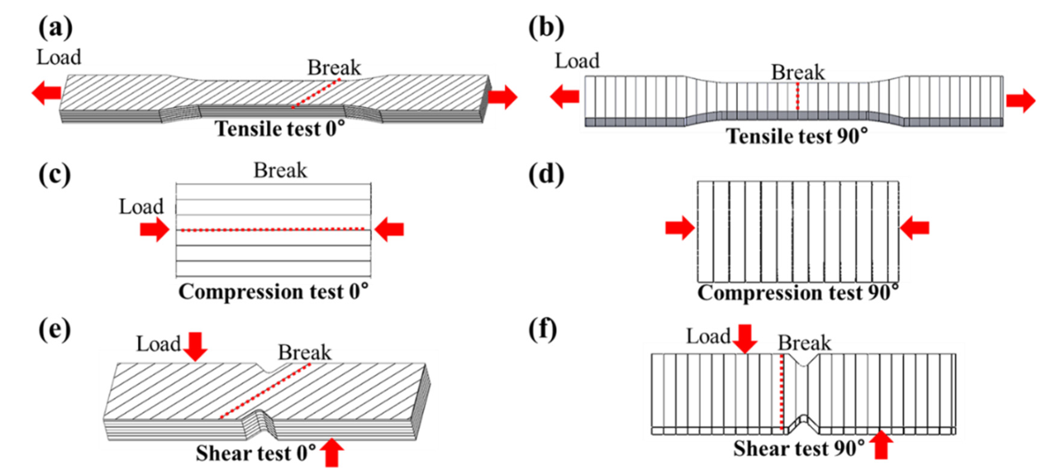
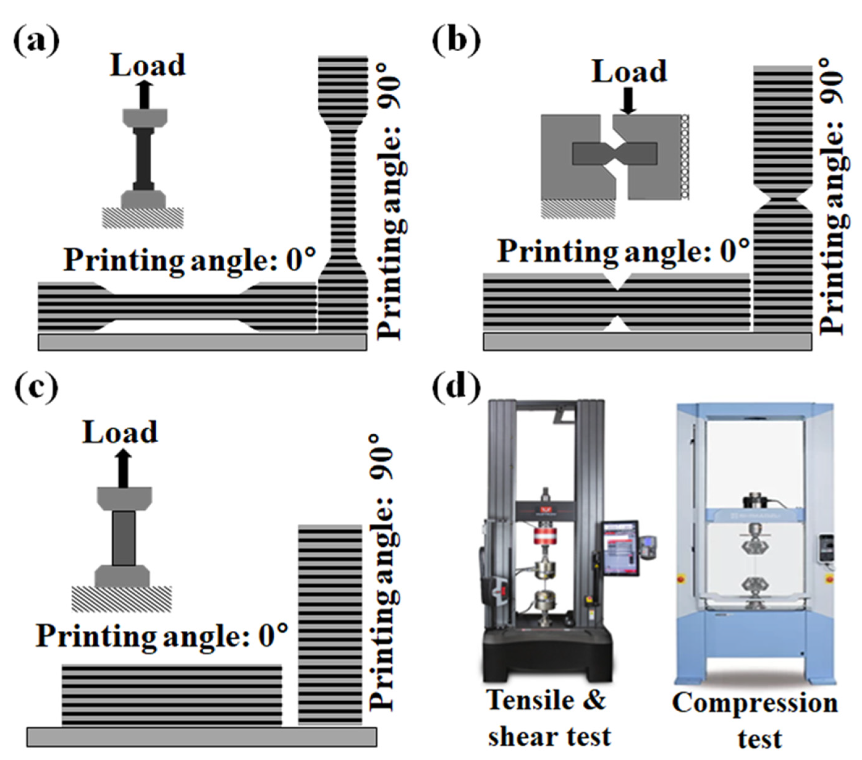
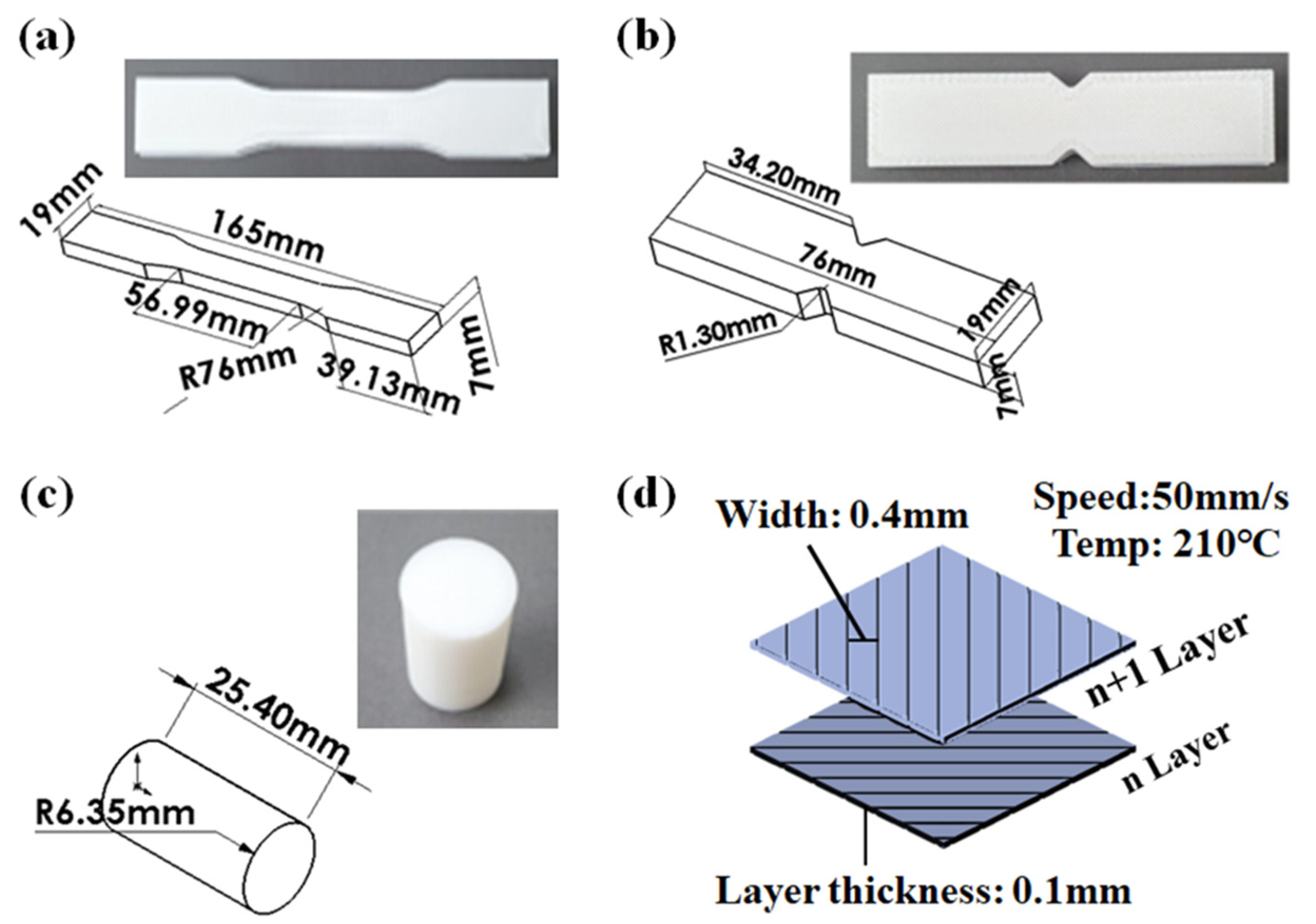
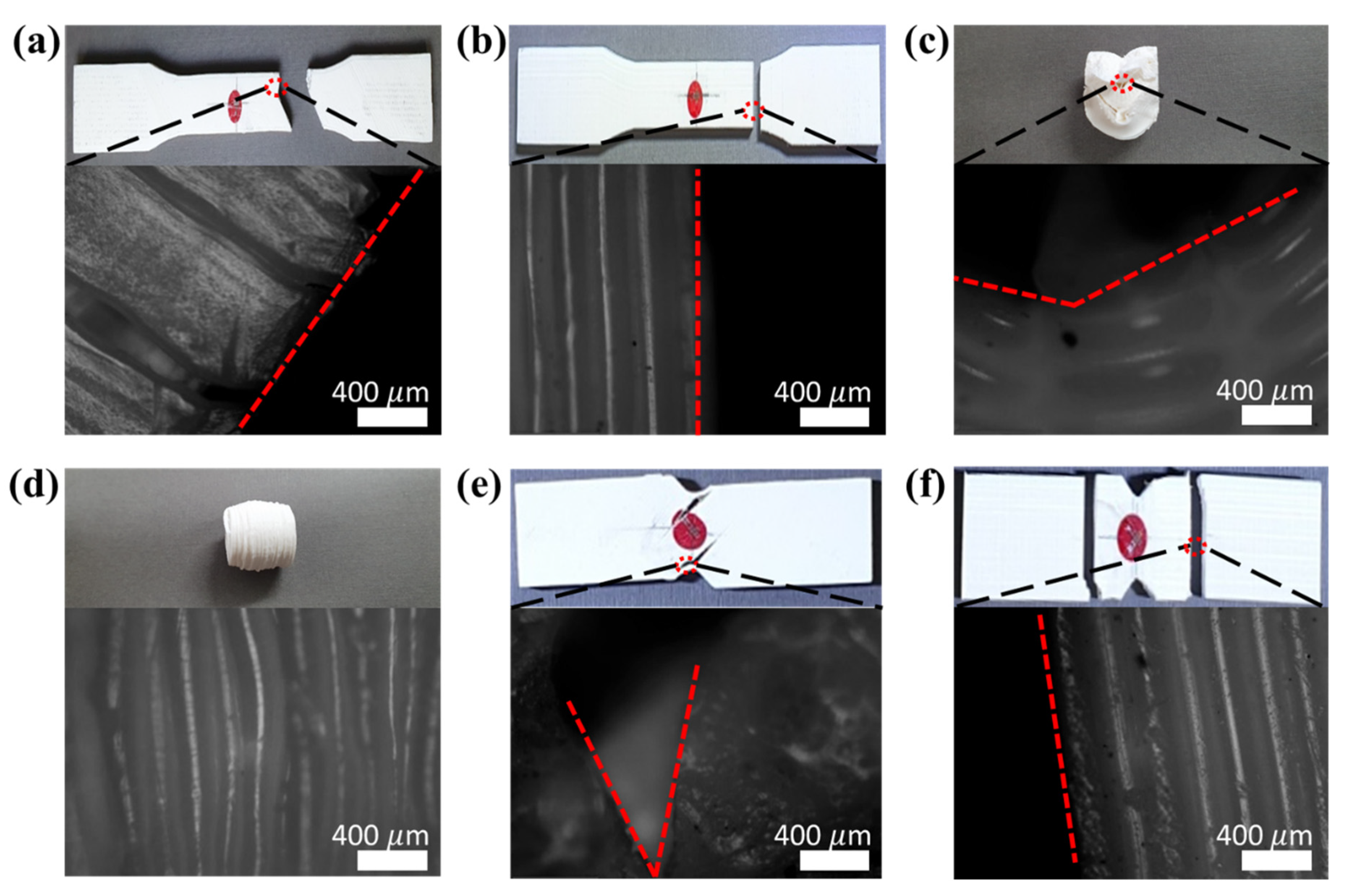
3.1. Material Tests of 3D-Printed Specimen
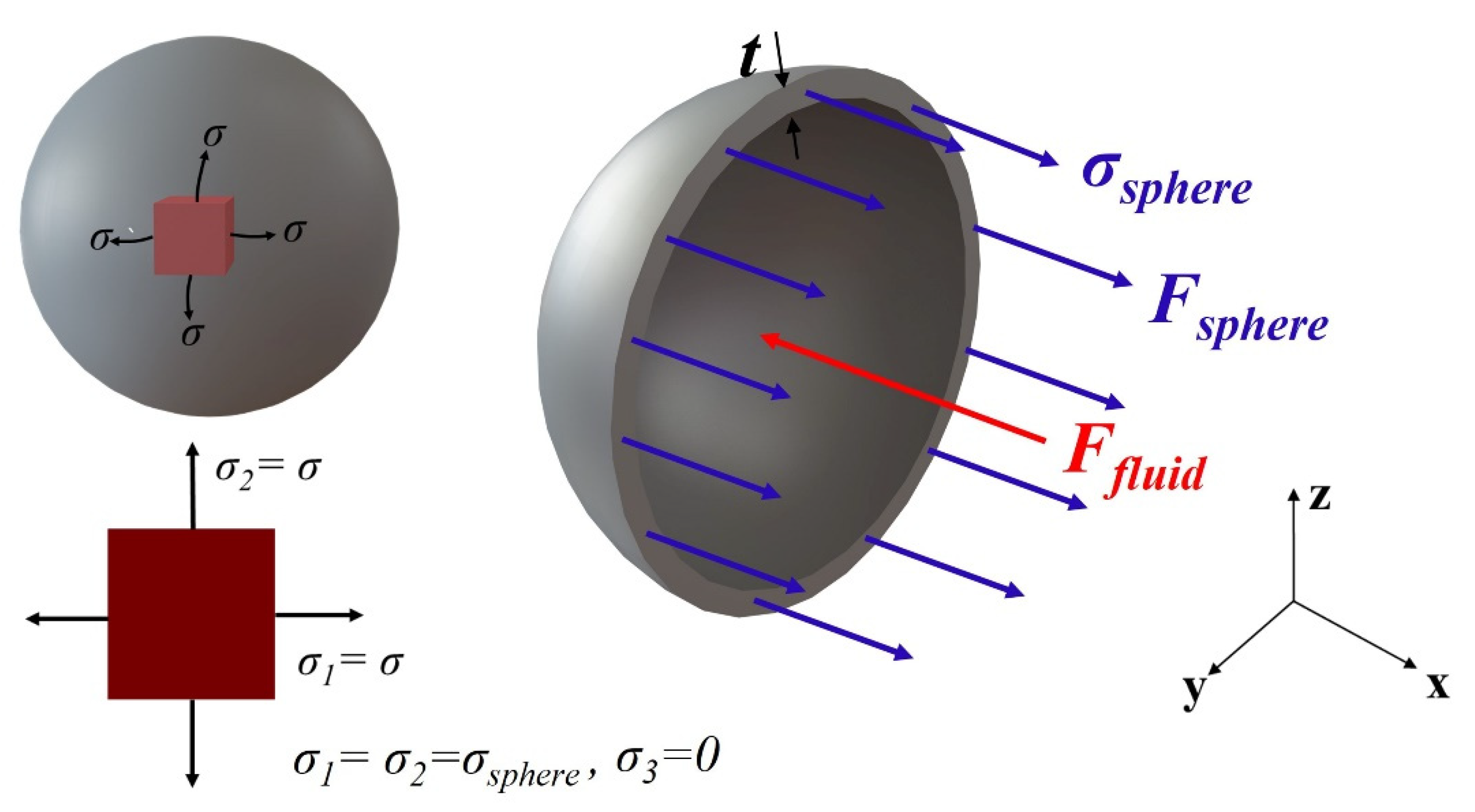
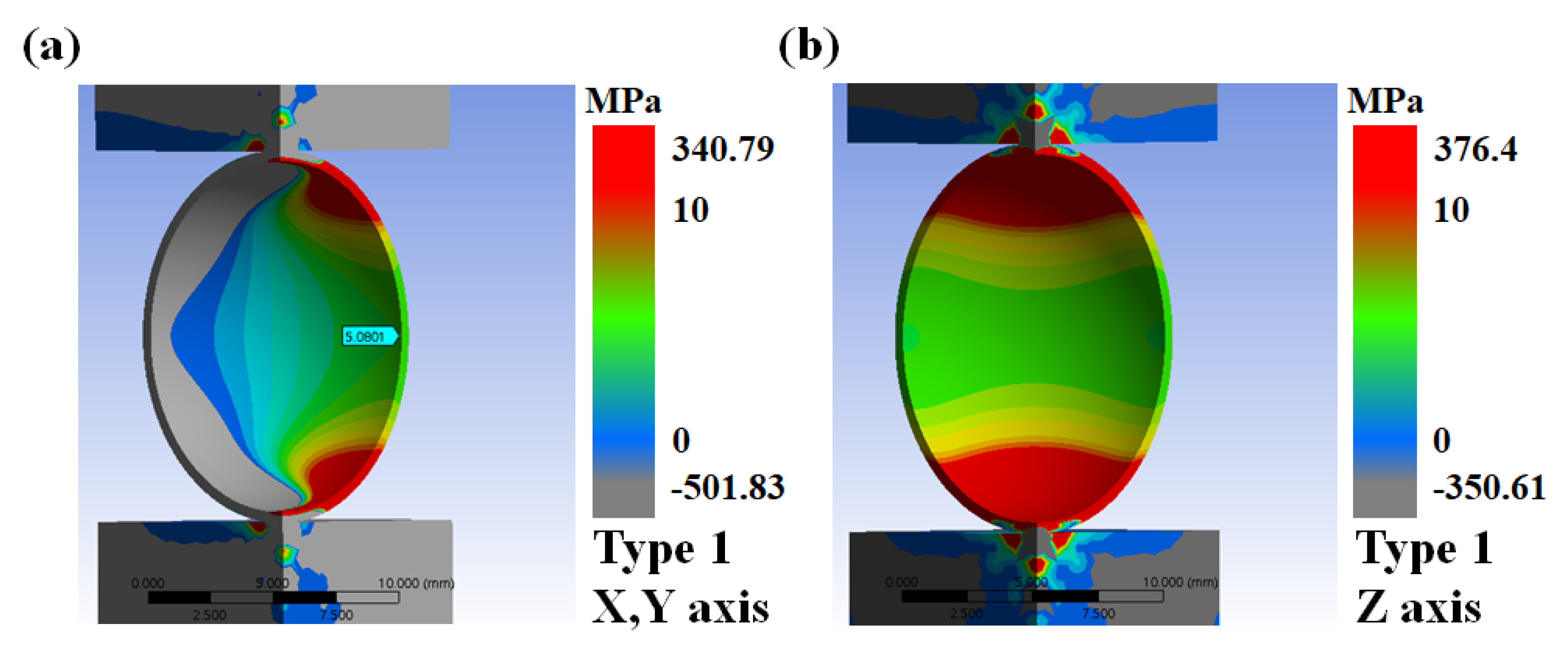
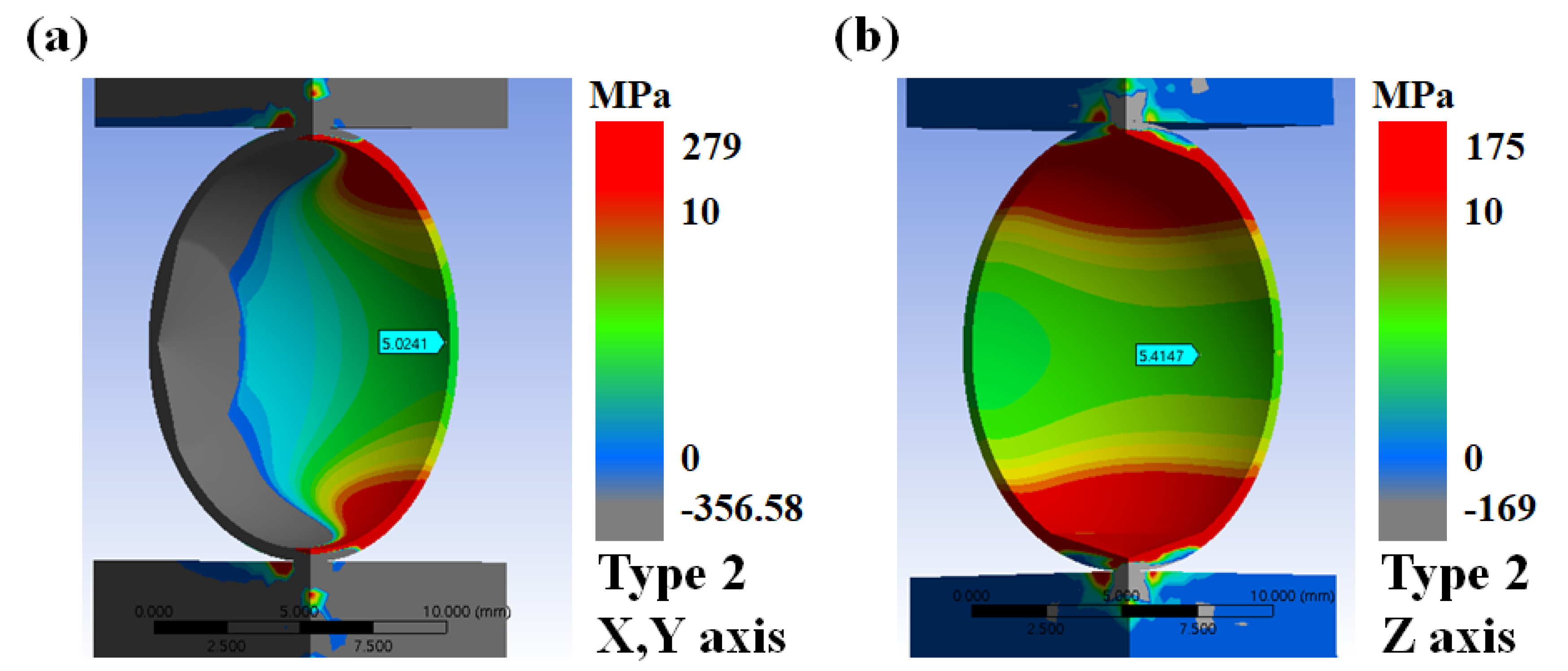
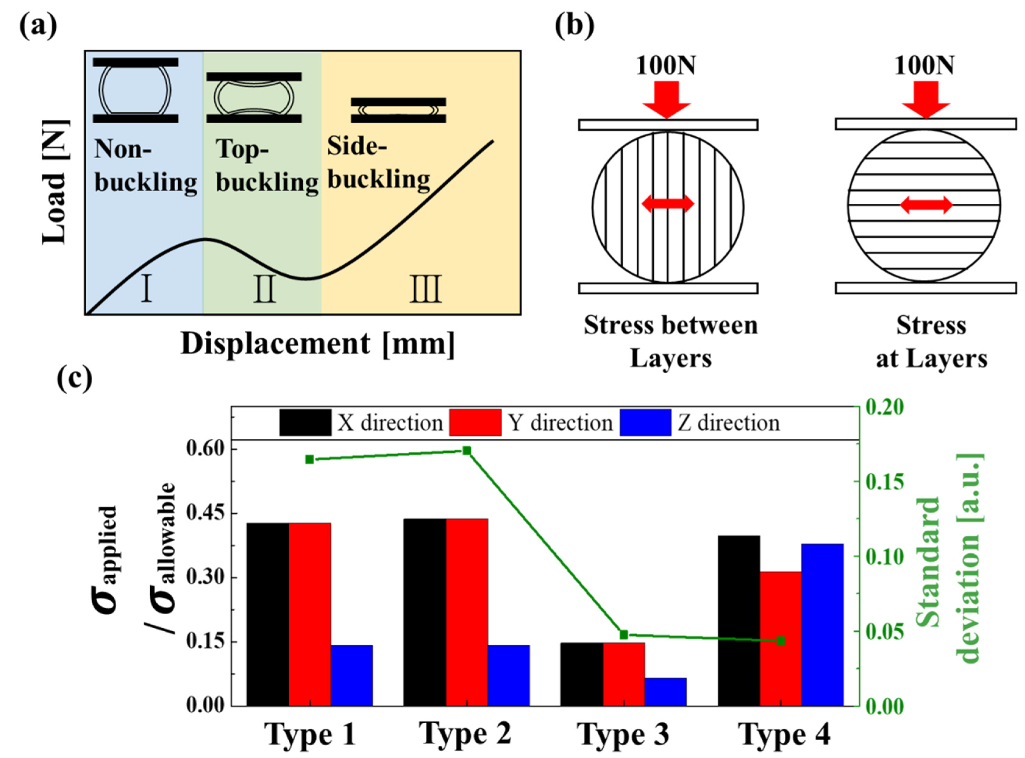
3.2. Finite Element Method Analysis of 3D-Printed Capsules
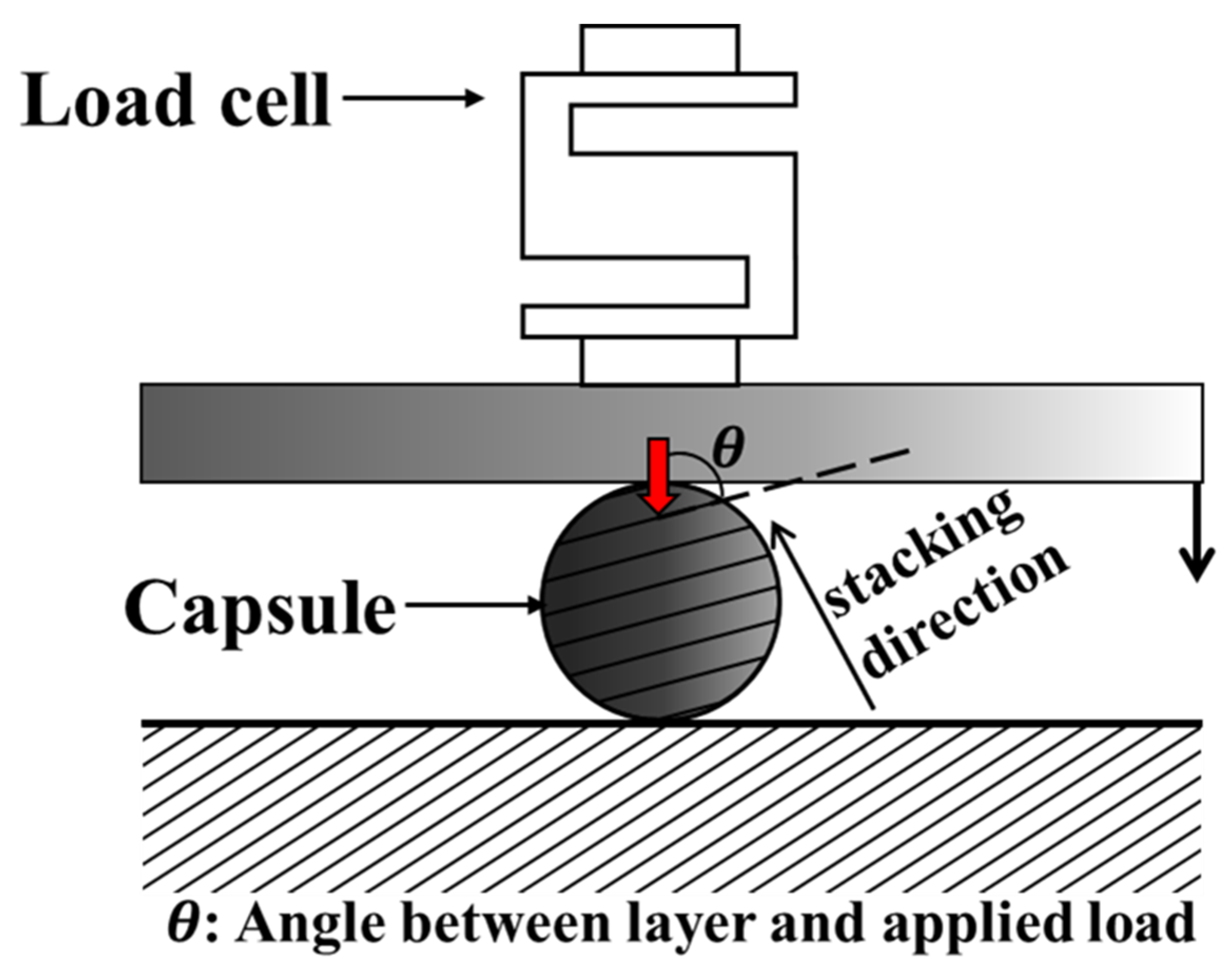
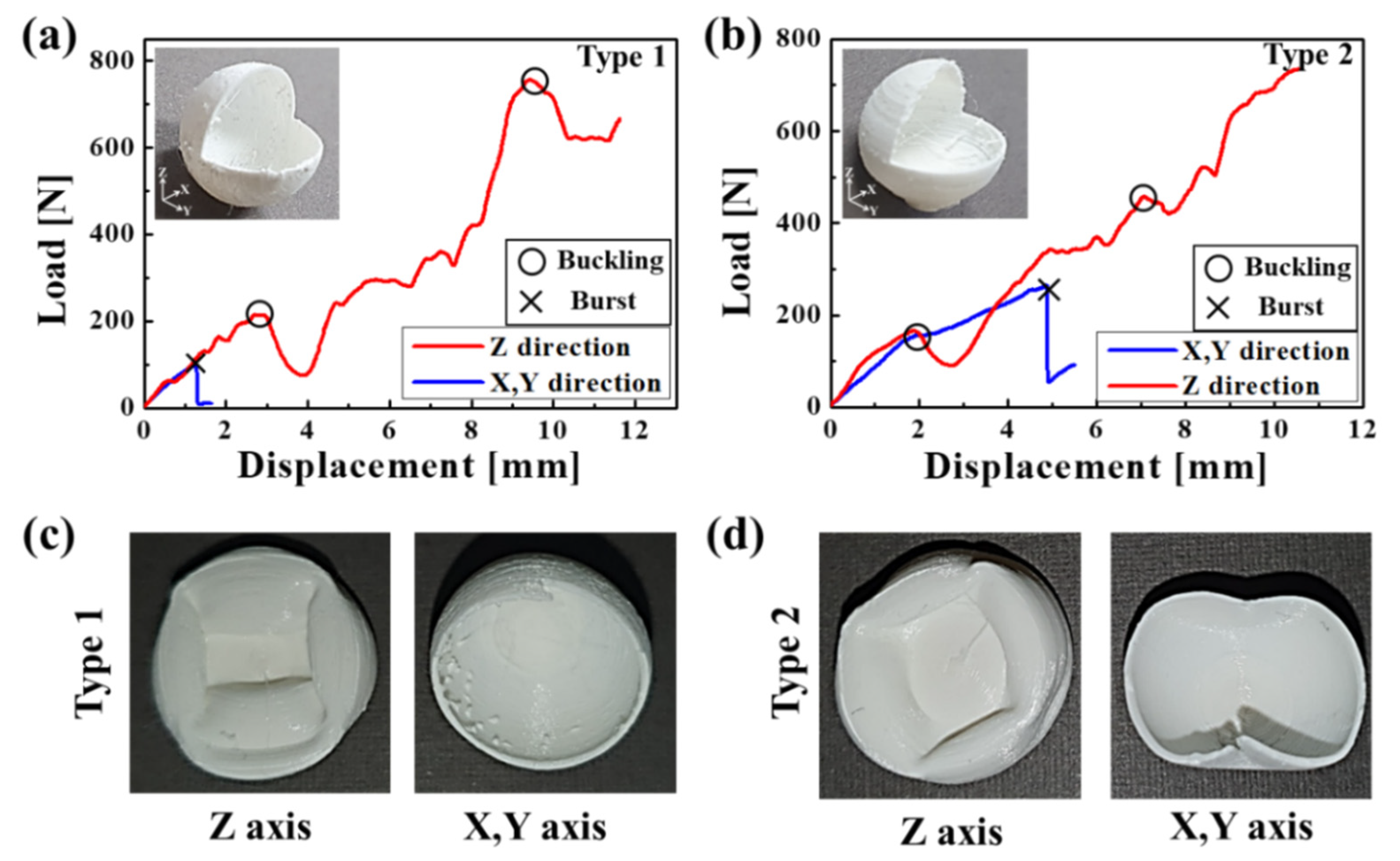
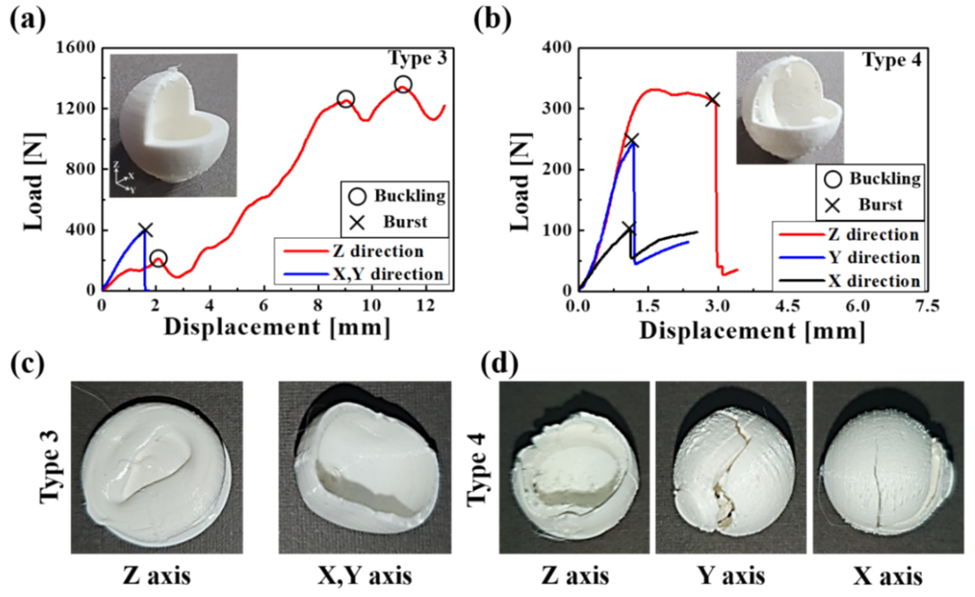
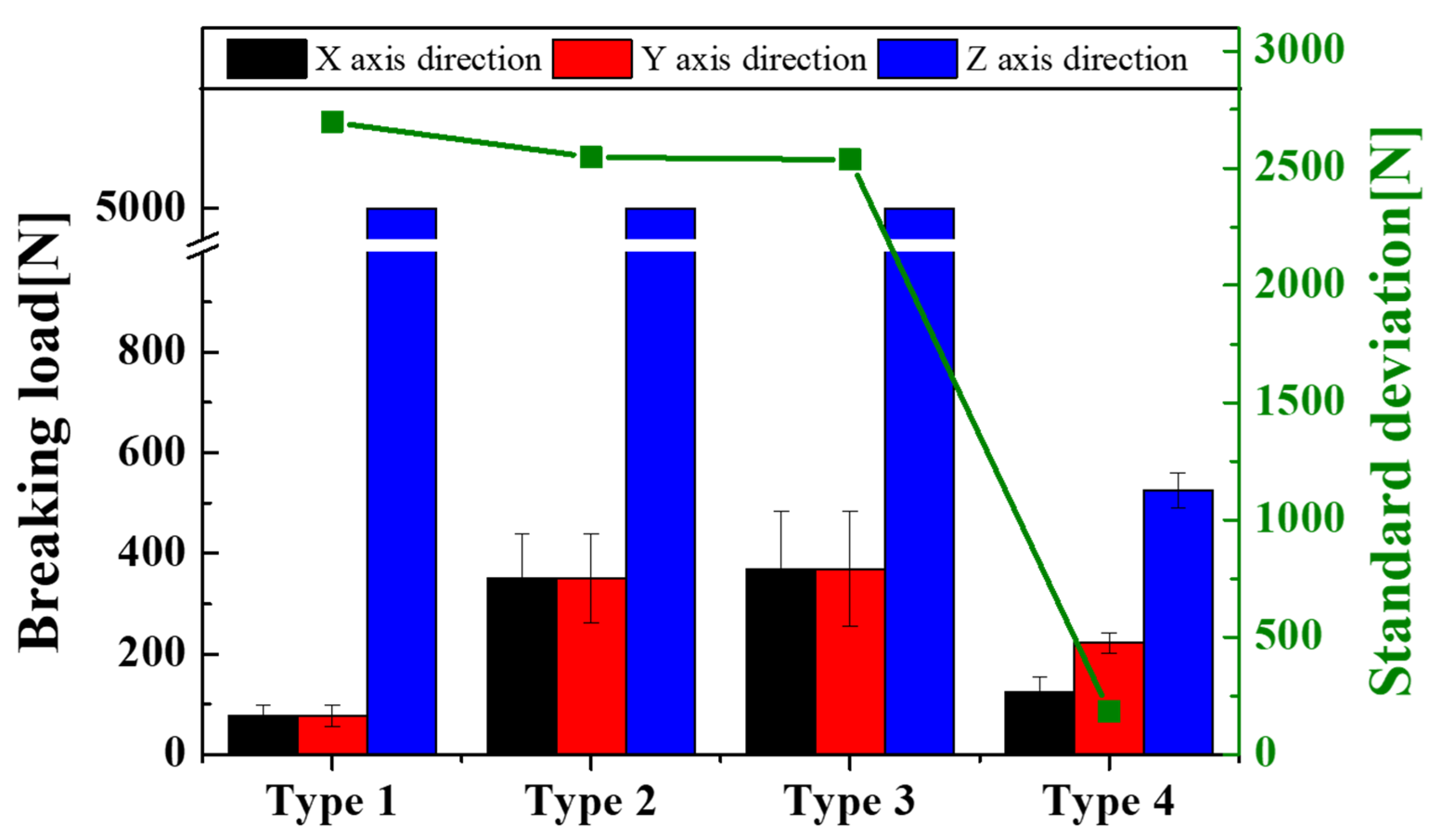
3.3. Fracture Strength Tests of 3D-Printed Capsules
4. Conclusions
Author Contributions
Funding
Institutional Review Board Statement
Informed Consent Statement
Data Availability Statement
Acknowledgments
Conflicts of Interest
Appendix A

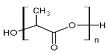
| PLA Chemical Structure | PLA Components | Properties | Values |
|---|---|---|---|
 | PolyLactic Acid (>90%) | Melt mass flow rate | 6.09 g/10 min |
| N,N’- Ethylene Bistearamide (<5%) | Melting temperature | 145~160 °C | |
| Typical antioxidant (<5%) | Diameter | 2.8 mm | |
| Typical pigment (<5%) | Printing temperature | 190~240 °C |

| Mechanical Properties | Values | |
|---|---|---|
| Tensile strength | X-axis direction | 38.11 (MPa) |
| Tensile strength | Y-axis direction | 38.11 (MPa) |
| Tensile strength | Z-axis direction | 11.9 (MPa) |
| Young’s modulus | X-axis direction | 3.06 (GPa) |
| Young’s modulus | Y-axis direction | 3.06 (GPa) |
| Young’s modulus | Z-axis direction | 2.64 (GPa) |
| Shear strength | XY plane | 13.89 (MPa) |
| Shear strength | YZ plane | 28.05 (MPa) |
| Shear strength | XZ plane | 28.05 (MPa) |
| Shear modulus | XY plane | 0.981 (GPa) |
| Shear modulus | YZ plane | 0.937 (GPa) |
| Shear modulus | XZ plane | 0.937 (GPa) |
| Compression strength | X-axis direction | −30.05 (MPa) |
| Compression strength | Y-axis direction | −30.05 (MPa) |
| Compression strength | Z-axis direction | −40.26 (MPa) |
| Poisson ratio | XY plane | 0.28 (a.u.) |
| Poisson ratio | YZ plane | 0.33 (a.u.) |
| Poisson ratio | XZ plane | 0.33 (a.u.) |
| Item | Properties | Value |
|---|---|---|
| Contacts | Type | Rough |
| Update stiffness | Each iteration, Aggressive | |
| Pinball region | Radius | |
| Pinball radius | 5 mm | |
| Mesh(Triangular cell) | Physics preference | Mechanical |
| Capsule element size | 0.2 mm | |
| Plate element size | 1.2 mm | |
| Type 1 nodes | 316,944 | |
| Type 1 elements | 62,292 | |
| Type 2 nodes | 586,842 | |
| Type 2 elements | 360,104 | |
| Type 3 nodes | 778,166 | |
| Type 3 elements | 503,135 | |
| Type 4 nodes | 803,045 | |
| Type 4 elements | 515,354 |


References
- Cailleux, E.; Pollet, V. Investigations on the development of self-healing properties in protective coatings for concrete and repair mortars. In Proceedings of the 2nd Internatinal Conference on Self-Healing Materials, Chicago, IL, USA, 28 June–1 July 2009. [Google Scholar]
- Calvo, J.G.; Pérez, G. Development of ultra-high performance concretes with self-healing micro/nano-additions. Construct. Build. Mater. 2017, 138, 306–315. [Google Scholar] [CrossRef]
- Dong, B.; Fang, G.; Ding, W. Self-healing features in cementitious material with urea–formaldehyde/epoxy microcapsules. Constr. Build. Mater. 2016, 106, 608–617. [Google Scholar] [CrossRef]
- Gilford, J.; Hassan, M.M. Dicyclopentadiene and Sodium Silicate Microencapsulation for Self-Healing of Concrete. J. Mater. Civ. Eng. 2014, 26, 886–896. [Google Scholar] [CrossRef]
- Tran, D.P. Quasi-brittle self-healing materials: Numerical modeling and applications in civil engineering. Ph.D. Thesis, National University of Singapore, Singapore, 2011. [Google Scholar]
- Tittelboom, V.K. Self-Healing Concrete through Incorporation of Encapsulated Bacteria- or Polymer-Based Healing Agents. Ph.D. Thesis, Ghent University, Ghent, Belgium, 2012. [Google Scholar]
- Victor, C.L.; Yun, M.L. Feasibility study of a passive smart self-healing cementitious composite. Compos. Part B Eng. 1998, 29, 819–827. [Google Scholar]
- Dry, C.M. Design of self-growing, self-sensing and self-repairing materials for engineering applications. In Proceedings of the Smart Materials and Mems, Melbourne, VIC, Australia, 13–15 December 2000. [Google Scholar]
- Joseph, C.; Jefferson, A. Experimental investigation of adhesive-based self-healing of cementitious materials. Mag. Concr. Res. 2010, 62, 831–843. [Google Scholar] [CrossRef] [Green Version]
- Dry, C. Matrix cracking repair and filling using active and passive modes for smart timed release of chemicals from fibers into cement matrices. Smart Mater. Struct. 1994, 3, 118–123. [Google Scholar] [CrossRef]
- Dry, C.; McMillan, W. Three-part methylmethacrylate adhesive system as an internal delivery system for smart responsive concrete. Smart Mater. Struct. 1996, 5, 291–300. [Google Scholar] [CrossRef]
- Dry, C.; Corsaw, M. A comparison of bending strength between adhesive and steel reinforced concrete with steel only reinforced concrete. Cem. Concr. Res. 2003, 33, 1723–1727. [Google Scholar] [CrossRef]
- Wang, J.; Tittelboom, K.V. Use of silica gel or polyurethane immobilized bacteria for self-healing concrete. Constr. Build. Mater. 2012, 26, 532–540. [Google Scholar] [CrossRef]
- Hilloulin, B.; Van Tittelboom, K.; Gruyaert, E.; De Belie, N.; Loukili, A. Design of polymeric capsules for self-healing concrete. Cem. Concr. Compos. 2015, 55, 298–307. [Google Scholar] [CrossRef] [Green Version]
- Mihashi, H.; Kaneko, Y. Fundamental study on development of intelligent concrete characterized by self-healing capability for strength. Concr. Res. Technol. 2000, 22, 441–450. [Google Scholar]
- Sun, G.; Zhang, Z. Mechanical strength of microcapsules made of different wall materials. Int. J. Pharm. 2002, 242, 307–311. [Google Scholar] [CrossRef]
- Feng, X.; Zhuo, N. Selfhealing mechanism of a novel cementitious composite using microcapsules. In Proceedings of the International Conference on Durability of Concrete Structures, Zhejiang University, Hangzhou, China, 26 November 2008; pp. 195–204. [Google Scholar]
- Xia, H. Self-Healing of Engineered Cementitious Composites (ECC) in Concrete Repair System. Master’s Thesis, Delft University of Technology, Delft, The Netherlands, 2010. [Google Scholar]
- Janssen, D. Water Encapsulation to Initiate Self-Healing in Cementitious Materials. Master Thesis, Delft University of Technology, Delft, The Netherlands, 2011. [Google Scholar]
- Yang, Z.; Hollar, J. A self-healing cementitious composite using oil core/silica gel shell microcapsules. Cem. Concr. Compos. 2011, 33, 506–512. [Google Scholar] [CrossRef]
- Perez, G.; Erkizia, E. Synthesis and characterization of epoxy encapsulating silica microcapsules and amine functionalized silica nanoparticles for development of an innovative self-healing concrete. Mater. Chem. Phys. 2015, 165, 39–48. [Google Scholar] [CrossRef]
- Koh, E.; Kim, N.K. Polyurethane microcapsules for self-healing paint coatings. RSC Adv. 2014, 4, 16214. [Google Scholar] [CrossRef]
- Wiktor, V.; Jonkers, H.M. Quantification of crack-healing in novel bacteria-based self-healing concrete. Cem. Concr. Compos. 2011, 33, 763–770. [Google Scholar] [CrossRef]
- Sisomphon, K.; Copuroglu, O. Application of encapsulated lightweight aggregate impregnated with sodium monofluorophosphate as a self-healing agent in blast furnace slag mortar. Heron 2011, 56, 13–32. [Google Scholar]
- Jyothi, N.V.N.; Prasanna, M.P. Microencapsulation Techniques, Factors Influencing Encapsulation Efficiency: A Review. Internet J. Nanotechnol. 2010, 3, 187–197. [Google Scholar] [CrossRef]
- Brown, E.N.; Sottos, N.R. Fracture testing of a self-healing polymer composite. Exp. Mech. 2002, 42, 372–379. [Google Scholar] [CrossRef]
- Liviana, R.; Costantino, D.G. 3D printed multicompartmental capsules for a progressive drug release. Ann. 3D Print. Med. 2021, 3, 100026. [Google Scholar]
- Jacek, K.; Aneta, S. Concept of Using 3D Printing for Production of Concrete–Plastic Columns with Unconventional Cross-Sections. Materials 2021, 14, 1565. [Google Scholar]
- Bose, S.; Vahabzadeh, S.; Bandyopadhyay, A. Bone tissue engineering using 3D printing. Mater. Today 2013, 16, 496–504. [Google Scholar] [CrossRef]
- Ayesha, S.; Al Mamun, A.; Wahid, F. 3D-printed concrete: Applications, performance, and challenges. J. Sustain. Cem. Based Mater. 2019, 9, 127–164. [Google Scholar]
- Ferdous, W.; Aravinthan, T.; Manalo, A.; Erp, G.V. Composite railway sleepers-new developments and opportunities. In Proceedings of the 11th International Heavy Haul Association Conference, Perth, WA, Australia, 21–24 June 2015. [Google Scholar]
- Tochukwu, C.O.; Dominika, S.; Basel, A.; Abdullah, I.; Ka-Wai, W.; Mohamed, A.A. A lower temperature FDM 3D printing for the manufacture of patient-specific immediate release tablets. Pharm. Res. 2016, 33, 2704–2712. [Google Scholar]
- Ngo, T.D.; Kashani, A. Additive manufacturing, (3D printing): A review of materials, methods, applications and challenges. Compos. Part. B 2018, 143, 172–196. [Google Scholar] [CrossRef]
- Xin, W.; Man, J. 3D printing of polymer matrix composites: A review and prospective. Compos. Part B Eng. 2017, 110, 442–458. [Google Scholar]
- Ferreira, R.T.L.; Amatte, I.C. Experimental characterization and micrography of 3D printed PLA and PLA reinforced with short carbon fibers. Compos. Part B Eng. 2017, 124, 88–100. [Google Scholar] [CrossRef]
- Shahrubudin, N.; Lee, T.C. An overview on 3D printing technology: Technological, materials, and applications. Procedia Manufact. 2019, 35, 1286–1296. [Google Scholar] [CrossRef]
- Baich, L.; Manogharan, G. Study of infill print design on production cost-time of 3D printed ABS parts. Int. J. Rapid Manuf. 2015, 5, 308–319. [Google Scholar] [CrossRef]
- Boparai, K.; Singh, R. Comparison of tribological behaviour for Nylon6-Al-Al2O3 and ABS parts fabricated by fused deposition modelling: This paper reportsa low cost composite material that is more wear-resistant than conventional ABS. Virtual Phys. Prototyp. 2015, 10, 59–66. [Google Scholar] [CrossRef]
- White, S.R.; Sottos, N.R. Autonomic healing of polymer composites. Nature 2001, 409, 794–797. [Google Scholar] [CrossRef] [PubMed]
- Daniyar, S.; Beibit, Z.; Aidana, S.; Mustakhim, A.; Asma, P.; Didier, T. Optimisation of strength properties of FDM printed parts-A Critical review. Ann. 3D Polym. 2021, 13, 1587. [Google Scholar]
- Zhou, Y.-G.; Su, B.; Turng, L.-S. Deposition-induced effects of isotactic polypropylene and polycarbonate composites during fused deposition modeling. Rapid Prototyp. J. 2017, 23, 869–880. [Google Scholar] [CrossRef]
- Raju, M.; Gupta, M.K.; Bhanot, N.; Sharma, V.S. A hybrid PSO–BFO evolutionary algorithm for optimization of fused deposition modelling process parameters. J. Intell. Manuf. 2019, 30, 2743–2758. [Google Scholar] [CrossRef]
- Vishwas, M.; Basavaraj, C.; Vinyas, M. Experimental investigation using taguchi method to optimize process parameters of fused deposition Modeling for ABS and nylon materials. Mater. Today Proc. 2018, 5, 7106–7114. [Google Scholar] [CrossRef]
- Różyło, P.; Wysmulski, P.; Falkowicz, K. Fem and Experimental Analysis of Thin-Walled Composite Elements Under Compression. Int. J. Appl. Mech. Eng. 2017, 22, 393–402. [Google Scholar] [CrossRef] [Green Version]
- Oldrich, S.; Pavlína, M.; Vlastimil, B. Non-Linear Analysis of an RC Beam Without Shear Reinforcement with a Sensitivity Study of the Material Properties of Concrete. Slovak J. Civ. Eng. 2020, 28, 33–43. [Google Scholar]
- Yu, Z.; Yuansong, C. Novel mechanical models of tensile strength and elastic property of FDM AM PLA materials: Experimental and theoretical analyses. Mater. Des. 2019, 181, 108089. [Google Scholar]
- Durgun, I.; Ertan, R. Experimental investigation of FDM process for improvement of mechanical properties and production cost. Rapid Prototyp. J. 2014, 20, 228–235. [Google Scholar] [CrossRef]
- Robert, S.; Smith, J.D. Axial compression of hollow elastic spheres. J. Mech. Mater. Struct. 2010, 5. [Google Scholar] [CrossRef] [Green Version]
- Feng, W.W.; Yang, W. On the Contact Problem of an Inflated Spherical Nonlinear Membrane. J. Appl. 1973, 40, 209–214. [Google Scholar] [CrossRef]
- Nascimento, D.F.D.; Avendaño, J.A. Flow of Tunable Elastic Microcapsules through Constrictions. Sci. Rep. 2017, 7, 11898. [Google Scholar] [CrossRef] [PubMed] [Green Version]
- Mohamed, R.; Dominique, B.B. Identification of the elastic properties of an artificial capsule membrane with the compression test: Effect of thickness. J. Colloid Interface Sci. 2006, 301, 217–226. [Google Scholar]
- Keller, M.W.; Sottos, N.R. Mechanical Properties of Microcapsules Used in a Self-Healing Polymer. Exp. Mech. 2006, 46, 725–733. [Google Scholar] [CrossRef] [Green Version]


Publisher’s Note: MDPI stays neutral with regard to jurisdictional claims in published maps and institutional affiliations. |
© 2021 by the authors. Licensee MDPI, Basel, Switzerland. This article is an open access article distributed under the terms and conditions of the Creative Commons Attribution (CC BY) license (https://creativecommons.org/licenses/by/4.0/).
Share and Cite
Lim, T.; Cheng, H.; Song, W.; Lee, J.; Kim, S.; Jung, W. Simulated and Experimental Investigation of Mechanical Properties for Improving Isotropic Fracture Strength of 3D-Printed Capsules. Materials 2021, 14, 4677. https://doi.org/10.3390/ma14164677
Lim T, Cheng H, Song W, Lee J, Kim S, Jung W. Simulated and Experimental Investigation of Mechanical Properties for Improving Isotropic Fracture Strength of 3D-Printed Capsules. Materials. 2021; 14(16):4677. https://doi.org/10.3390/ma14164677
Chicago/Turabian StyleLim, Taeuk, Hao Cheng, Wonil Song, Jasung Lee, Sunghoon Kim, and Wonsuk Jung. 2021. "Simulated and Experimental Investigation of Mechanical Properties for Improving Isotropic Fracture Strength of 3D-Printed Capsules" Materials 14, no. 16: 4677. https://doi.org/10.3390/ma14164677
APA StyleLim, T., Cheng, H., Song, W., Lee, J., Kim, S., & Jung, W. (2021). Simulated and Experimental Investigation of Mechanical Properties for Improving Isotropic Fracture Strength of 3D-Printed Capsules. Materials, 14(16), 4677. https://doi.org/10.3390/ma14164677