Abstract
Using the methods of electron microscopy and X-ray analysis in combination with measurements of the electrical resistance and magnetic susceptibility, the authors have obtained data on the peculiar features of pre-martensitic states and martensitic transformations, as well as subsequent decomposition, in the alloys with shape memory effect of Cu–14wt%Al–3wt%Ni and Cu–13.5wt%Al–3.5wt%Ni. For the first time, we established the microstructure, phase composition, mechanical properties, and microhardness of the alloys obtained in the nanocrystalline state as a result of severe plastic deformation under high pressure torsion and subsequent annealing. A crystallographic model of the martensite nucleation and the rearrangements β1→β1′ and β1→γ1′ are proposed based on the analysis of the observed tweed contrast and diffuse scattering in the austenite and the internal defects in the substructure of the martensite.
1. Introduction
The external temperature and force mechanical effects, as well as magnetic and electric fields, which provide for thermoelastic martensitic transformations (TMTs), allow one to actualize a number of unusual and extremely important physical phenomena in various materials. The single- or multiple-cyclically reversible shape memory effects (SMEs) and gigantic superelasticity and damping associated with TMT enable the classification of smart shape memory alloys (SMAs) into a special separate class of practice-important structural multifunctional materials [1,2,3,4,5,6,7,8,9,10]. Recently, it was found that SMAs are also distinguished by gigantic caloric effects, including magnetocaloric, electrocaloric, barocaloric, and elastocaloric, which are in demand in effective environmental thermo-refrigeration technologies [11,12,13,14,15,16,17,18,19,20,21,22,23].
The rapid development of modern equipment and technologies dictates the creation of such smart materials that can be practically used in a wide range of temperature-, power-, and other operating conditions. However, a significant disadvantage of polycrystalline smart materials, with the exception of binary alloys of titanium nickelide, is their low ductility and brittleness, which exclude the implementation of these unique effects not only in cyclic multiple, but even in a single application. Therefore, the problems of the optimum alloying and development of methods for plasticization of the polycrystalline materials with SMEs for their various industrial applications are becoming increasingly important, but remain unsolved.
Copper-based β SMAs, such as Cu-Al-Ni, Cu-Zn-Al, and Cu-Zn-Sn, are distinguished by their much lower cost, better thermal and electrical conductivity, and superior technological processability in comparison with, for example, alloys based on titanium nickelide [1,2,3,24]. Moreover, these β alloys in a single-crystalline state demonstrate excellent SME characteristics. However, in a usual coarse-grained (CG) state these polycrystalline alloys are also of extremely low plasticity, crack resistance, and fatigue life characteristics [2,24]. This does not permit the actualization of SMEs that the β single crystals are typical of.
The specific cause of the brittleness due to the operation of the mechanism of intergranular fracture typical of copper alloys that are metastable with respect to TMT is the low value of the modulus C′ = C11−C12/2 and, accordingly, the high anisotropy of the elastic modulus, A = C44/C′ (12–13 units) [25], whereas for elastic-isotropic low-modulus and ductile alloys of titanium nickelide, the value of A is correspondingly only 1–2 units [26,27,28,29,30,31,32,33,34,35]. The large elastic anisotropy at TMT leads to significant elastic stresses at the joints of martensitic packets and particularly at the grain boundaries, and their magnitude and localization at the boundaries are greater the larger the alloy grains are. The decrease in plasticity is aggravated by the grain-boundary chemical liquation and heterogeneous decomposition in these CG alloys—primarily at temperatures below the eutectoid decomposition boundary (TED), which is close to 840 K [2]. Intergranular brittleness is one of the key reasons preventing the practical application of these SMAs.
At the same time, it has been established that a noticeable improvement in the strength- and plasticity-related characteristics of NiTi-based SMAs is achieved upon the formation of an ultra-fine-grained (UFG) structure [35,36,37,38,39,40,41,42,43,44,45,46,47,48,49,50]. The formation of the UFG structure is provided by advanced thermo-deformational technologies with employment of such methods of severe plastic deformation (SPD) as equal channel angular pressing (ECAP), high pressure torsion (HPT), high temperature pressing, multipass rolling, and drawing into strips, rods, or wire.
In our works [35,51,52,53,54,55,56,57] it was found that a radical decrease in the grain size during SPD and, accordingly, an increase in the length of the grain boundaries permits us to make the level of embrittlement of SME β-copper alloys lower. Any other methods of refinement of the grain structure of these alloys using alloying additives, heat treatment, rapid quenching, powder metallurgy, and a number of other corresponding methods turned out to be generally unsuccessful [58,59,60,61,62,63,64,65]. The aim of this presented work was to study (i) the structure of the Cu-Al-Ni-based SMAs and (ii) the effect of the SPD by means of HPT and subsequent annealing on the grain sizes, structural phase transformations, mechanical properties, and hardness.
2. Materials and Methods
The master alloys of nominal compositions Cu–14%Al–3%Ni (that at room temperature (RT) is in the austenitic state) and Cu–13.5%Al–3.5%Ni ((in wt.%) that is in the martensitic state) were melted out from the components Cu, Al, and Ni of high purity (99.99%). The chemical composition of the alloys, determined by the spectroscopy analysis, is given in Table 1. The alloys were subjected to hot smith forging at 1173–1273 K to the rod with the cross section of 20 × 20 mm2 and to water quenching from 1223 K after heating for 10 min. A number of samples of the alloys were subjected to repeated water quenching from 1273 K after preceding heating for 30 min. For the thorough refinement of the grain structure of the alloys we employed an HPT method under a pressure of 6 GPa at RT to 1, 5, and 10 revolutions in highly rigid Bridgman-anvil-type units (flat or with a cylindrical recess in the lower anvil. Specimens for HPT were made in the form of disks—10 mm in diameter in the case of flat anvils and 20 mm in diameter in the case of anvils with a cylindrical recess, 0.5 and 1.2 mm thick, respectively. The value of the true deformation (e) of specimen disks at half the radius was 4.65 or 6.0 units. Isochronous isothermal anneals of the HPT specimens were performed in the temperature range 373–873 K (in increments of 100 K) for 30 min. The critical temperatures of the start (Ms, As) and end (Mf, Af) of the direct (Ms, Mf) and reverse (As, Af) TMTs were determined in the course of the cyclic temperature measurements of the magnetic susceptibility χ(T) and electrical resistivity ρ(T), with a rate close to 5 K/min. The structure and the phase composition were investigated using the methods of X-ray diffractometry (XRD), optical metallography (OM), transmission- (TEM) and scanning electron microscopy (SEM), including EBSD analysis (of diffraction of back-scattered electrons), and MEA (energy-dispersive X-ray spectral microelement analysis). XRD studies were performed in the copper radiation CuKα. The microscope TEM Tecnai G2 30 (Hillsboro, OR, USA) was employed at an accelerating voltage of 300 kV; SEM Quanta 200 (Hillsboro, OR, USA), equipped with the system Pegasus, was employed at an accelerating voltage of 30 kV. Thin foils of Ø3 mm (in diameter) were prepared by the method of ion etching on the setup Fischione 1010 IonMill (Pittsburgh, PA, USA) by cutting out the 1/2 radius and subjecting it to grinding–polishing on a Metaserv 250 apparatus (Chicago, IL, USA). Vickers’s microhardness measurements (HV) were performed on a Micromet 5101 (Chicago, IL, USA) with a pyramidal diamond indenter at a load of 1 N (100 g). Tensile tests of small-sized flat specimens with a length of 10.0, thickness of 0.25, and width of 1.0 mm were performed at a special automated setup. Tensile tests of standard bulk specimens of Ø3 mm thickness were performed at an Instron 8862 setup (Buckinghamshire, UK).

Table 1.
Chemical spectroscopic analysis of the alloys Cu–14Al–3Ni and Cu–13.5Al–3.5Ni.
3. Results and Discussion
3.1. Pre-Martensitic State
As was determined, hot deformation via forging of the studied Cu-based alloys permits refining of austenite grains down to 0.5–1 mm [54,55]. However, the further subsequent cooling in air entails (i) the decomposition by the scheme β→β1+γ2 (at temperatures above the TED close to 840 K) and (ii) eutectoid decomposition via β1→α+γ2 (at temperatures below TED) (Figure 1a), which is in good correspondence with the known data from [2,24,35,51,52,53,54,55,56,57,58,59,60,61,62,63,64,65]. However, quenching of the alloys after their hot forging allows us to prevent the eutectoid decomposition. At the same time, it is important to take into account that β-austenite at temperatures above TED and Ms successfully and successively experiences two transitions (disorder–order), namely, β→β2(B2)→β1(D03). In this case, as is known, an inheritance of the long-range atomic order from the initial atomically ordered austenitic phase is provided by emerging martensite. The latter fact, as a consequence, determines the thermal elastic behavior of the martensite [1,2,3,4,5,6].
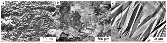
Figure 1.
(a) SEM image and (b,c) OM images of the alloys (a,c) Cu–13.5Al–3.5Ni and (b) Cu–14Al-3Ni in the (a) as-cast, (b) austenite, and (c) martensite states.
Figure 1b,c displays typical OM images of (b) the grain microstructure of β1-austenite and (c) the intragrain packet-pyramidal pairwise-twinned morphology of martensite of the quenched alloys (b) Cu–14Al–3Ni and (c) Cu–13.5Al–3.5Ni.
During TEM studies, in the bright- and dark-field images of quenched austenite one can observe the so-called tweed contrast (Figure 2a,b and Figure 3a) and anti-phase domain boundaries (APB) (Figure 2c). Through such examinations, an intricate regular visual image of non-radial diffuse scattering is revealed in selected area electron diffraction (SAED) patterns, and its reconstruction in the form of a reciprocal lattice leads to a successive revealing of the arrangement of the flat diffuse {111}* (walls) that pass through all the nodes hkl, excluding the central node 000 [6,66].
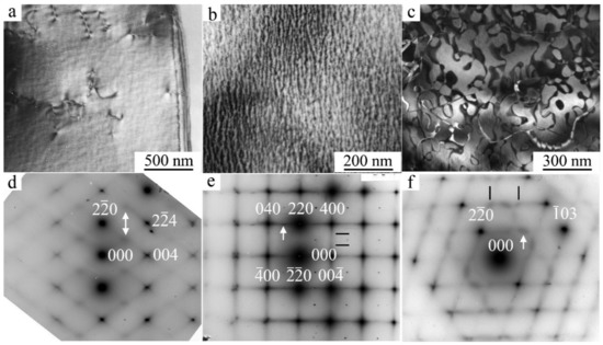
Figure 2.
(a–c) Dark-field TEM images of (a,b) tweed contrast, (c) anti-phase boundaries, in the β1-austenite of the quenched alloy Cu–14Al–3Ni and (d–f) corresponding SAED patterns, with zone axis (d) [110], (e) [001], and (f) [331]; D03. Observations at (a,d) 450 K, and (b,c,e,f)–RT.
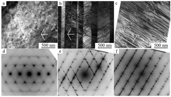
Figure 3.
(a) Dark-field and (b,c) bright-field TEM images (a) of the tweed contrast in the β1-austenite, (b) twinned γ1′ martensite, and (c) β1′ martensite of the quenched alloy Cu–13.5Al–3.5Ni, and (d–f) their corresponding SAED patterns, with zone axis close to [111]; D03. Observations (a,d) at 450 K, and (b,c,e,f)–at RT. In addition, white lines (a,b,c) denote the directions of the normals to (i) the planes of {111} type, (ii) the traces of stacking faults, and (iii) the micro twins of the martensitic crystals with the same habit, which is close to {111} D03.
The distribution of the intensity of diffuse scattering in these {111}* walls varies heterogeneously and naturally, depending on the position in the reciprocal lattice. A more intense diffuse scattering is observed in the vicinity of any fundamental reflections, rather than in the space between them (Figure 2 and Figure 3). According to the diffraction theory, the intensity of diffuse scattering is determined by the relation I ~ |A(k)|2 (g e(k))2, where A(k) is the displacement waver amplitude, k is the wave vector, e(k) is the polarization vector, and g is the diffraction vector [6,66]. The scattering is absent (except for the cases of double diffraction) if the g is directed in parallel to the plane of a diffuse wall (i.e., the vector g lies perpendicular to e(k) in the given planes passing through the center of the reciprocal lattice). The most intense diffuse streaks in the reciprocal lattice are located parallel to k || <110>*, and e(k) || <10>*. A specific feature of the diffuse scattering effects with increasing diffraction angle is the preservation of their sufficiently high intensity in comparison with decreasing intensity of Bragg fundamental reflections. Such scattering occurs at the temperature of observation in situ above Ms by 100–150 K (Figure 2 and Figure 3).
As the temperature approaches Ms, the intensity of the diffuse streaks along <112>* and particularly <110>* (according to qualitative and quantitative estimations) increases gradually and, apart from this, which is very important, at these streaks one can see the increase in intensity of the extra reflections (called satellites) at the positions in the space of reciprocal lattice close to 1/2<220>*, 1/3<220>*, 1/6<220>*, 1/2<422>*, and 1/3<422>*. The appearance of such satellites is due to the coexistence of different lattice waves of displacements of kn atoms in a crystal that is metastable with respect to the shear transition. The diffraction pattern of such a crystal with a single wave of type kn is described by the vector relation g = ghkl + Σpn·kn, where kn is the wave vector from the star of the kn vector, {kn}, pn are integers. In this case, it is possible to register paired satellites of the first order (±k). In highly symmetric crystals, multi-ray states are realized, including, for example, two rays of the same set. Therefore, if we denote k1 = 2/3 2/3 0, k2 = 2/3 0 2/3, then k1 + k2 = 4/3 2/3 2/3. This resulting vector (in units of 2π/a) in the reduced Brullien zone corresponds to the vector k′ = 200−(4/3 2/3 2/3) = 2/3 −2/3 −2/3 and characterizes the diffraction vectors as second order. In other words, satellites of the type 1/3<222>*, 2/3<222>*, and 1/3<422>* that are significantly weaker than the 1/3<220>* satellites of the first order have an interference origin and are second-order satellites. This, in particular, means that the ω-shaped displacements in the D03 and L21 lattices, the presence of which was assumed in [66], can be obtained by the interference of waves 1/3 <220>k<1–10>e. In addition, it should be noted that the position of the satellites of type 1/2 <422>* coincides with the punctures of the Ewald sphere by diffuse streaks along <110>* (see Figure 2d and [66]). Thus, only satellites of the type 1/2<220>*, 1/3<220>*, and 1/6<220>* should be considered the effects of independent diffuse scattering together with continuous diffuse scattering along <110>* (see Figure 4). The black profile lines represent the experimental profiles of intensity that were measured using the program Digital Micrograph when processing SAED patterns. The red profile lines represent the profiles of intensity calculated by employing a Gauss Function within the framework of the program Origin for fundamental reflections. The blue lines represent the calculated profiles for the satellites of the types 1/6 <220>, 1/3 <220>, and 1/2 <220>. Typical features of (i) the observed diffraction tweed contrast and (ii) diffuse electron scattering, i.e., their periodic “reoccurrence”, regular attenuation, and amplification, make it possible to describe them (namely, i and ii) by certain spectra (see Figure 5) of the transversal and longitudinal vibration waves in the k-space of reciprocal lattice, which are characterized by the wave (k) and polarization (e(k)) vectors, and, correspondingly, to identify them with the localized waves of atomic displacements in the space of crystal, which sufficiently periodically distort, on average, the original crystal lattice (Figure 6). The projections of vectors e(k), shown in Figure 5 by streaks or arrows, are characteristic of the waves of enhanced amplitude and, consequently, of intense scattering. The interpretation of the data obtained gives an opportunity to construct a physical model of the real metastable microstructure and its evolution and assess its possible role in the nucleation mechanism of TMT in low-modulus Cu-Al-Ni alloys.
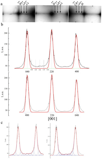
Figure 4.
(a) Fragments of SAED pattern with zone axis [001]. (b) Intensity profile when scanning the diffuse scattering between the fundamental reflections of types 040–220–400 or −400–−2-20–0−40. (c) Intensity profile along the diffuse streaks with calculated profiles for satellites of type 1/6 <220>, 1/3 <220>, 1/2 <220>.
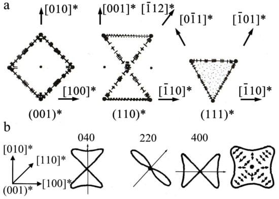
Figure 5.
(a) Spectra of waves of atomic displacements in the form of the planar cross sections (001)*, (110)*, and (111)* of reciprocal k space and (b) in vicinity of reciprocal lattice nodes in the (001)* planes.
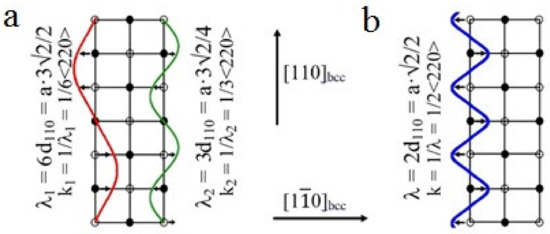
Figure 6.
Schemes of shuffling offsets type of 1/6<220>k<1–10>e and 1/3<220>k<1–10>e (a) and 1/2<220>k <1–10>e (b) that provide transformations cubic lattice to D03 or L21.
As is known, in the BCC alloys the scattering between reflections in the form of diffuse walls {111}* is stipulated by short-wave acoustic (predominant-in-the-spectrum) vibrations of the non-correlated displacements of closely packed (along <111>) chains of atoms relative to each other. At pre-martensitic softening of elasticity moduli, particularly of C’ [6,25,67], the amplitudes and correlations of such specific linear <111> defects of atomic displacements gradually grow in the close-packed planes {110} (Figure 6). If the correlations of atomic displacements in these planes are greater than correlations between the planes themselves relative to each other, then the diffuse scattering has the form of solid (continuous) streaks along <110>*. Judging by the character of tweed contrast, such atomic displacements are localized within the volume of nano regions, whose distorted structure and symmetry can be described by the short-range order of atomic displacements (SOD) [34,35,66].
When the alloys are cooled down below a certain temperature TIncS (at the stage of weakly Incommensurate Satellites), the diffraction pattern commences to be characterized by the appearance of satellites–in the main of the type “1/6”, “1/3” and/or “1/2”, which correspond to long-period modulation (LPM) nanostructures: (for brevity)–LPM-1 (for the satellites of type “1/3”) and LPM-2 (for the satellites of type “1/2”) [35]. The satellite-related stage can be considered an independent state that replaces SOD domains and is characterized by quasi-stable intermediate LPM shear substructures. Since all crystallographically equivalent variants of the distortion-induced (orientation-related and anti-phase) LPM nanodomains located statistically along the volume of the austenitic phase exist, the structure of such alloys on average retains the original cubic symmetry. According to the diffraction-provided data, the internal distortion and local symmetry of the LPM domains differ from the original one and obviously approach the structure of the future martensitic phases as much as possible while maintaining a coherent connection under the conditions of the specifics of the progressive local instability of the crystal lattice of the austenitic phase and its anharmonism [6,35]. In the experiment, this structure-related nucleation mechanism of the TMT is confirmed, firstly, by the fact that the reflections in the SAED patterns from martensite crystals of the β1′ and γ1′ phases are located precisely in the positions of the satellites of 1/3 and 1/2 types (see Figure 3). Secondly, at the nucleation and growth of these phases, there emerge a large number of planar chaotically disposed stacking faults (SF) coplanar to the basal plane of (001) type for both of the martensitic phases β1′ and γ1′. In this case, one can observe specific characteristic features of the contrast (Figure 3b,c) and diffuse scattering in the form of distinct narrow continuous streaks passing through Bragg reflections (Figure 3e,f).
In the modern non-classic crystal-structural description, LPM domains are by themselves special-type nano nuclei (with the structure non-identical to that characteristic of either the austenite phase or would-be martensite phases) and can play the role of real physical centers of nucleation of martensite crystals. Thus, at a certain synchronization between the uniform longitudinal distortion of <100>k<100>e Bain type and the transversal static waves of atomic displacements describing the structure of the nano domains LPM-1 by the two waves of 1/6<220>k<1–10>e and 1/3<220>k<1–10>e type (Figure 5 and Figure 6), the structure of the β1′ martensite of 18R type in the studied alloys can be obtained (see Figure 6a and Figure 7a). Additionally, the combination between (i) the uniform longitudinal of <100>k<100>e Bain distortion and (ii) the mode of the periodic shuffling displacements of the type 1/2<220>k <1–10>e, which form the structure of the nano domains LPM-2, crystallographically presets the trend towards the rearrangement β1→γ1’ (Figure 6b and Figure 7b). Apparently, in this case, violation of the ideal stacking of atoms along the basal plane (001) is feasible, and this entails the occurrence of various disturbances in the form of stacking faults (Figure 7).
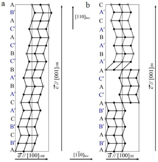
Figure 7.
Schematics of crystal lattice rearrangement of type (a) D03→18R and (b) D03→2H martensite.
Interestingly, when measuring the temperature dependences ρ(T) and χ(T) in the thermal cycles (cooling from RT to 90 K–heating to RT), not are only the hysteresis loops of the TMT are determined, but the pre-martensitic deviations of the dependences from linearity of the curves ρ(T) and χ(T) can also be found, despite their being a bit narrower in an interval of the temperatures 20–25 K, which follows from the data of the TEM analysis, obviously being more sensitive (Figure 8). The temperature dependences for the Cu-14Al-3Ni alloy shown in Figure 8b demonstrate the TMT hysteresis loops when measured in other thermal cycles cooling–heating (curve 1) or heating–cooling (curve 2). The temperatures determined by the two-tangent method are shown in Table 2 and are consistent with the XRD phase-composition data (Figure 9).
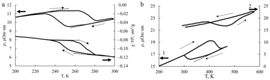
Figure 8.
(a) The temperature dependences ρ(T) and χ(T) of the Cu-14Al-3Ni alloy after quenching from 1223 K in water in the measurement cycle 300 K→LN→300 K; and (b) temperature dependences of ρ(T) of the Cu-14Al-3Ni alloy after HPT in the measurement cycles 300 K→LN→470 K→300 K (curve 1) and 300 K→573 K→300 K (curve 2) (LN is an abbr. for liquid nitrogen). The dotted line shows the pre-transition deviations from the linear dependence of ρ(T) and χ(T) interval of 20–25 K; inside hysteresis loops.
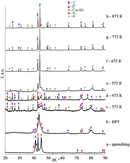
Figure 9.
XRD spectra for the alloy Cu–14Al–3Ni after its (a) quenching, (b) HPT of 10 rev, and (c–h) HPT of 10 rev + annealing at 373 K–873 K, 30 min. Temperatures of measurements: (a) 200 K, (b–h) RT.
As has already been noted, on the one hand, low values of elastic modulus, and on the other hand, the possibility of deformation-induced TMT, both these circumstances determine the unique specific features of the mechanical behavior of metastable alloys. In the next section, we will consider the results of applying SPD to the alloys studied in this work in order to create a nanocrystalline UFG state in them.
3.2. Structure, Phase Composition, and Mechnical Properties of SPD Alloys
According to XRD data, in the course of cooling below the temperature Ms in the studied quenched β1 Cu-Al-Ni alloys, two martensitic phases indicated as β1′ (of 18R type) and γ1′ (of 2H type) are formed (see Figure 9, curve (a)). It is established that an HPT of 10 revs at RT entails the formation of these alloys of a mixture of the three deformation-induced martensitic phases α′, β1′, and γ1′ (Figure 9, curve (b)) in accordance with [68]. The Bragg reflections detected in this case are significantly broadened (with a half width up to 2 degrees) and coincide with the most intense diffraction lines from these martensitic phases.
It is important to note that the hysteresis of the TMT (ΔT) in the HPT-treated alloy increases more than three times with a noticeable increase in all critical temperatures. According to the data of XRD analysis of the HPT-treated alloy subjected to annealing at 373 and 473 K, in the alloy, the martensitic phases β1′ and γ1′ are preserved and the γ2–Cu9Al4 phase of aging appears (see Figure 9, curves c, d). An annealing at temperatures higher than Af, namely, 573–773 K leads to the eutectoid decomposition of β1 austenite into the phases (α + γ2) (see Figure 9, curves e–g). Finally, the annealing at 873 K causes the decomposition of austenite with precipitation of the γ2 phase (Figure 9, curve h). Further cooling of the HPT-treated alloy, down to RT, is accompanied by the TMT in the retained β1 matrix. Therefore, in XRD analysis, β1-phase reflections, unlike martensitic reflections, are not detected (see Figure 9).
TEM investigations have shown that as a result of HPT when increasing the number of revolutions from 1 to 10 (and, correspondingly, the degree of deformation) in both alloys, a (progressively) more uniform nano-grained martensitic structure is formed, which is characterized by a ring-wise distribution of Bragg reflections in the SAED patterns (see Figure 10 and Figure 11).
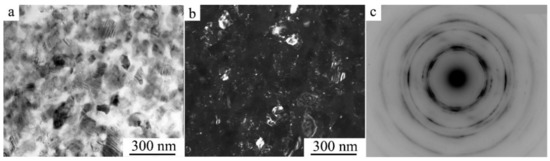
Figure 10.
(a) Bright- and (b) dark-field TEM images of the microstructure and (c) the corresponding SAED pattern for the Cu–14Al–3Ni alloy after its quenching from 1223 K and HPT of 10 revs.
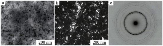
Figure 11.
(a) Bright- and (b) dark-field TEM images of the microstructure and (c) the corresponding SAED pattern for the Cu–13.5Al–3.5Ni alloy after its quenching from 1223 K and HPT of 10 revs.
According to the data of quantitative analysis of the bright- and dark-field TEM images taken from the alloys after their HPT of 10 revs, the sizes of the observed randomly oriented structural fragments that are most frequently occurring vary within the limits from 10 to 80 nm and are on average 30 nm. It is seen that the larger (in size) of them has plate-like nano twins. Indexing of SAED patterns has shown that the nanocrystalline structure formed in the alloys contains predominantly three martensitic phases (α′ + β1′ + γ1′). The ring distribution of the reflections implies the presence of both small- and large-angle misorientations of the martensitic nanophases that make up the ultrafine-grained (UFG) structure.
We have studied the effect of the temperature of annealing on the microstructure of the HPT-treated alloys using SEM microscopy and revealed the following. Anneals of martensite at 373 and 473 K did not lead to noticeable size-morphological changes in the martensitic UFG structure formed as a result of HPT. However, anneals in the austenite condition (in the temperature range from 573 to 873 K) have provided a noticeable growth of globular grains in the process of formation of UFG states in the HPT-treated alloys (Figure 12). Employment of the orientational EBSD method has permitted us to establish the specific mechanism of decomposition in the HPT alloys, as a result of which one can observe the formation of a UFG structure of alternating nanophases (see, for example, Figure 13).
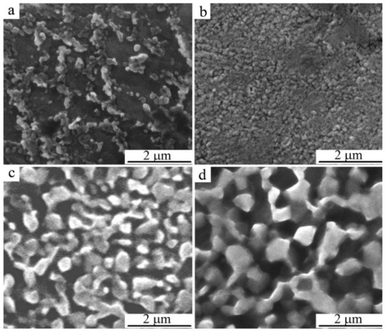
Figure 12.
SEM images of the microstructure of the Cu-14Al-3Ni alloy after the HPT of 10revs and anneals for 30 min at temperatures of (a) 373, (b) 673, (c) 773, and (d) 873 K.
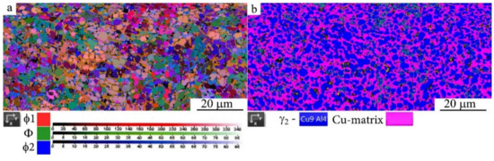
Figure 13.
(a) Map of the disorientation of the structure in Euler angles and (b) phase map of image quality in EBSD mode for HPT Cu-14Al-3Ni alloy of n = 10 revolutions, and annealing at 873 K, for 60 min.
Low-temperature annealing below Ms initiates pro-eutectoid homo- and heterogeneous decomposition of martensite in the HPT-treated alloys with precipitation of an aluminum-enriched γ2 nano phase (Figure 14). Namely, the depletion of matrix of aluminum by 1–2 at.% causes the destabilization of austenite and an increase in the critical temperatures of the TMT by 70–150 K (see Figure 8 and Table 2).
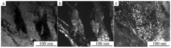
Figure 14.
(a) Bright- and (b,c) dark-field TEM images of the aging martensite microstructure in the coarser grain of the Cu-14Al-3Ni alloy after the HPT of 10 revs and isochronous anneals (for 30 min) at 373 K.
A study of the alloys in the state of β1-austenite after HPT of 10 revs and high-temperature anneals was also performed via TEM methods (Figure 15 and Figure 16). According to the data of bright-field TEM investigations, it was confirmed that in the UFG β1 matrix, in the course of annealing, there was a formation and growth of the globular nano crystallites of (in the main) three phases, namely, the β1, α, and γ2 phases, judging from the results of indexing of corresponding SAED patterns (the values of the average size <dG> of the grains–crystallites are given in Table 3). We have a right to draw a conclusion that annealing at 573 K triggers in the reverted β1-austenite a combined reaction of the process of recrystallization and eutectoid (α + γ2) decomposition. In this case, with a background of coarser recrystallized grains, the smaller (comparative) grains–crystallites are still distinguished by the intense deformation-related contrast and they remain virtually unaltered in their sizes. On average, the value of <dG> is close to 100 nm (see Figure 15a’). The reflections in the corresponding SAED patterns still exhibited a continuous (solid) ring distribution (Figure 15a’).
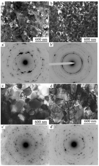
Figure 15.
(a–d) Bright-field TEM images of microstructure and (a’–d’) corresponding SAED patterns of the Cu-14Al-3Ni alloy after the HPT of 10 revs and isochronous anneals (for 30 min) at temperatures of: (a,a’) 573 K, (b,b’) 673 K, (c,c’) 773 K, and (d,d’) 873 K.
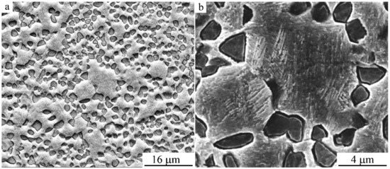
Figure 16.
SEM images of the microstructure of the Cu-14Al-3Ni alloy after the HPT of 10 revs and annealing at 1073 K for 10 s at (a,b) different magnifications.
Table 3.
Average size of grains of the Cu-14Al-3Ni alloy subjected to HPT of 10 revs and to different anneals.
An increase in the annealing temperature to 673 K led to almost complete primary recrystallization of the reverted β1-austenite and to the formation of a (β1 + α + γ2) nano-triplex structure in the composition of a homogeneous UFG austenite at an increased <dG> value close to 150 nm. The boundaries of grains–crystallites remained rounded and distorted, and the structure still retained an increased number density of defects (Figure 15b). Intensive enlargement of the α and γ2-phase globules formed in β1-austenite at <dG > close to 350 nm occurred at a higher isochronous annealing temperature of 773 K (Figure 15c). After annealing at 873 K, the <dG> for the β1 and γ2 phases is already close to 400 nm (Table 3, Figure 15d). Imaging of the boundaries of grains–crystallites of a nano-duplex (β1 + γ2) structure, which are inherited by martensite, becomes even more distinct, and one can observe a contrast between the twins in martensite. More “sharp” point reflections in the SAED patterns indicate a significant relaxation of the internal stresses and interfacial distortions in the UFG structure formed by the precipitated phases and martensite. The ring-shaped visual character of the less uniform distribution of point reflections in the SAED patterns of HPT-treated alloys after annealing at 673–873 K indicates the preservation of small-angle and large-angle random misorientations of the resulting globular grains–crystallites in the alloy (see Figure 15a’–d’). Another type of a bimodal single-phase UFG structure, the martensite UFG structure of HPT-treated alloys of the Cu-Al-Ni system, which was formed during short-term thermal action in the course of high-temperature annealing at 1073 K; for 10 s, is shown in Figure 16. An increase in the annealing time causes accelerated grain growth, since in this case the annealing temperature of 1073 K significantly exceeds TED, which is close in this case to 840 K, and this time the increase is inexpedient, as it leads to the softening of the alloy.
Thus, in the result of these TEM investigations it is established that anneals, starting from the temperatures above Af, lead to recrystallization of the reverted β1-D03 austenite in the HPT-treated alloys Cu–14Al–3Ni and Cu–13.5Al–3.5Ni. In this case, sufficiently homogeneous UFG states can be obtained, the average grain sizes of which increase after annealing at 573–873 K (30 min) in the range from 30 to 400 nm or reach 3.5 μm after short-term annealing at 1073 K, 10 s (Table 3).
In all cases, the obtained XRD and SAED patterns have shown the presence of γ2-phase reflections, both after low-temperature (below Ms) annealing at 373–473 K, when the HPT-treated alloy has experienced partial decomposition of martensite with the precipitation of disperse (fine) γ2 particles, and after high-temperature annealing as a result of eutectoid (α + γ2) decomposition of austenite at 573–773 K or its (of austenite) pro-eutectoid (β1 + γ2) decomposition at 873 K. If the matrix austenitic β1 phase was preserved after annealing, which is the case for all the selected regimes of treatment, the subsequent cooling to RT was accompanied by TMT.
Data of measurements of Vickers hardness (HV) at the 1/2 of radius of the specimen disks of the HPT-treated Cu-14Al-3Ni and Cu-13.5Al-3.5Ni alloys in dependence of the quenching and temperature of annealing are listed in Table 4 and Table 5 and shown in Figure 17. It is established that HV increases after HPT as the temperature of annealing rises, but HV after double quenching remains slightly lower than after single quenching.
Table 4.
Dependence of the microhardness of the Cu–14Al–3Ni alloy on the temperature of annealing for 30 min after quenching and HPT of n = 5 revs.
Table 5.
Dependence of the microhardness of the Cu-13.5Al-3.5Ni on the temperature of annealing for 30 min after quenching and HPT of n = 10 revs.
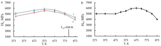
Figure 17.
Dependence of the microhardness HV of the HPT-treated alloys (a) Cu–14Al–3Ni (curve 1–quenching from 1223 K, curve 2–quenching from 1273 K) and (b) Cu–13.5–3.5Ni on the temperature of annealing for 30 min.
After their annealing at 573–673 K, the HPT-treated Cu-Al-Ni alloys had maximum HV values, up to 6000 MPa after single quenching from 1223 K and 5550 MPa after repeated quenching from 1273 K. The HPT increases HV by 1000 MPa in comparison with HV in the initial quenched austenite condition. The repeated (second) quenching causes the refinement of grain and a better homogenizing of the solid solution of alloys than single quenching; however, as a consequence, this has led to slightly lower values of HV.
The results of measurements of the tensile mechanical properties at RT of the Cu-14Al-3Ni alloy are shown in Table 6 and Figure 18. The tests showed that the quenched coarse-grained alloy had an ultimate tensile strength (σu) of 620 MPa, a critical stress of martensite shear (σM) 160 MPa, and a relative elongation to failure (δ) of 7%. The second quenching of the alloy with some softening due to the creation of a fine-grained state led to an increase in δ up to 11%. In the strengthened UFG alloy, subjected to HPT at RT, the value of δ decreased to 4%, and the destruction was brittle, without the formation of a neck. The plateau of phase fluidity in this case was absent in contrast to the cases of the quenched coarse-grained or the fine-grained alloy (where εM = 2%). The rise of the temperature of HPT of n revs to 423 K (by 130 K greater than RT) led to extremely high deformation-induced strengthening of the Cu-14Al-3Ni alloy and to a considerable growth of δ, whose value amounted to 12%. Therefore, in the HPT-treated alloy, the highest mechanical characteristics were achieved in complex. Thus, the yield strength has amounted to 1400 MPa, and the ultimate strength to 1450 MPa at a sufficiently high δ to failure (12%). Considerable changes in the mechanical properties of the alloy were observed after (i) HPT of 10 revs and (ii) isothermal annealing in the temperature range from 573 to 1073 K (see Table 6). All specimens are characterized by grain size conservation within the UFG structure.
Table 6.
Results of tensile mechanical tests of the Cu-14Al-3Ni alloy after different deformation–temperature treatments.
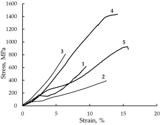
Figure 18.
Stress–strain curves taken in tensile tests of the Cu-14Al-3Ni alloy after different deformation–temperature treatments: (1) forging + quenching from 1223 K; (2) repeated quenching from 1273 K; (3) HPT, n=10 rev, at 293 K; (4) HPT, n = 10 rev, at 423 K; (5) HPT, n = 10 rev, at 293 K + 1073 K, for 10 s.
3.3. Fractographic Study
Fractographic investigations of the pattern of failure of the specimens after tensile tests showed that in the initial hot-forged quenched CG alloy the destruction of specimens took place in a brittle manner, predominantly via cleavage along the grain boundaries and large-scale packets of martensite crystals (Figure 19a). A nano-sized grain–subgrain structure after HPT of 10 revs has revealed the change in the type of fracture and the character of destruction of specimens (Figure 19b). In the latter case, on the fracture surface, there were many centers of localization of deformation with the formation of small flat dimples and, accordingly, low ridges of separation on the fracture surface. This, as a rule, is typical of the ductile (tenacious), intra-grain mechanism of failure of the alloys with low energy. However, the average size of dimples amounted to 2–5 μm, which was two orders greater than that of the elements of a UFG structure of the HPT-treated alloys. This circumstance testifies to the operation of the special intercrystalline mechanism of the fracture of their destruction, apparently along high-angle boundaries of the UFG structure, since in this case the size of cellular fragments (dimples) of separation during ductile–brittle fracture became two orders of magnitude smaller in comparison with the size of grains and regions of brittle cleavage in the initial coarse-grained alloy. This ultimately determined, in a number of cases, the increased ductility of the UFG alloys preliminarily subjected to HPT and consequent annealing (Figure 19b–d).
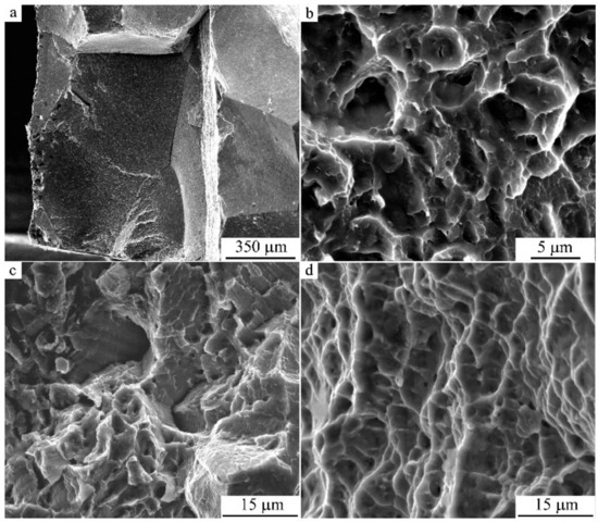
Figure 19.
(a–d) SEM images of fracture surfaces of the specimens of Cu-14Al-3Ni alloy after (a) hot-forging and quenching (HFQ); (b) HFQ + HPT, n = 10 revs; (c) double quenching (DQ), with second Q from 1273 K; and (d) DQ + HPT, n = 10 revs + uniaxial tensile treatment at 423 K.
Therefore, it has been established that SPD of the eutectoid Cu-Al-Ni alloys with SMEs is, in certain conditions, an effective method of radical refinement of their grain structure and, as a consequence, attaining the appearance of plasticization. In the present work we have shown that an HPT to the large plastic deformations allows us to attain mechanically induced TMT and the concurrently evolving formation of a homogeneous UFG structure of martensite in metastable austenitic Cu-Al-Ni alloys, which is the case in both studied alloys. The UFG structure is generally characterized by high hardness, strength, as well as by a higher stability of martensitic phases with respect to the case of reverse TMT. The critical temperatures of the TMT of the alloy Cu–14Al–3Ni subjected to HPT of 10 revs have exhibited an increase in value: Ms and Mf by 70 K, and As and Af by 160 K, (see Table 2). This allowed us to draw a conclusion that the increase in the temperatures of reverse TMT in the cycle of the heating and subsequent cooling when measuring ρ(T) is stipulated in the main, according to the data of phase analysis, by the precipitation effect of the γ2–Cu9Al4 phase (at the boundaries and inside the volume of martensite), which is responsible for both the dimensional and the chemical stabilization of martensitic grains–crystallites, the latter due to their depletion of aluminum and enrichment of copper (by 1–2 at.%, according to the data on Ms and Af). In this case, a known concentration dependence of the TMT temperatures on the composition in copper and aluminum [35] gives one the possibility of determining the chemical composition of the β1 matrix of quenched alloys of the system Cu–Al–Ni.
On the other hand, a number of specific features of the fine structure and phase composition of the alloys after HPT and isothermal annealing were revealed in combined analysis by the XRD, TEM, SEM methods, and measurements of ρ(T). It is established that at lower temperatures of annealing (373–473 K), namely, below Af, in the HPT-treated alloys one can find the preserved martensitic phases. In this case, the appearance of the reflections of the γ2 phase–“phase of ageing”, and the disappearance of the reflections of the strain-induced α’ phase, apparently transforming into β1′ martensite, are recorded. On the contrary, an annealing at higher temperatures, namely, above Af, leads to the disappearance of martensitic phases due to reverse TMT to a UFG austenite. In this case, at annealing below TED the reverted austenitic β1 phase is liable to experience a eutectoid (α + γ2) decomposition into a globular UFG nano-triplex structure, and at annealing above TED the precipitation of the γ2 phase with the formation of a nano-duplex (β1 + γ2) structure is expected. At quenching to RT or upon deformation, the appearance of TMT is possible.
It is important that post-deformation anneals of HPT-treated alloys have entailed the formation of structures capable of exhibiting SME and phase yielding in a wide range of stresses sufficient for the flow of martensite, namely, σM from 50 to 450 MPa (Table 6). Overall, anelastic deformation, including the formation of martensitic crystals, detwinning, and their reorientation in the direction of acting forces, provides an essential contribution to the ability of alloys to deform plastically. Thus, for instance, the alloy Cu–14Al–3Ni after HPT of 10 revs and short-term annealing at a temperature of 1073 K for 10 sec had δ of a relatively moderate value (13%), which was due to the combination of the values of the phase fluidity εM and duration of long-term stage of subsequent plastic deformation of martensite (Table 6). After attainment of the value σu = 900 MPa, there was a localization of the deformation with the development of a small reduction in the cross section of the neck.
4. Summary and Conclusions
In the present paper, two ternary SM alloys of close composition based on the Cu-Al-Ni system were chosen for investigation, namely, Cu-14%Al-3%Ni alloy in an austenitic state at RT, and Cu-13.5%Al-3.5%Ni alloy in a martensitic state at RT.
A detailed investigation of the fine structure, morphological features, and physical properties of austenite and martensite in the alloys after their quenching, SPD, and consequent annealing was carried out. Tensile mechanical properties of the alloys in the coarse, fine-grained, and ultrafine grain states and the mechanism of their fracture were established. From the analysis of the obtained results, taking into account the known data, the following conclusions can be drawn:
- Non-radial diffuse streaks and complex patterns of arrangement of diffuse satellites of type 1/2, 1/3, and 1/6 were revealed and systematically investigated in detail using the diffraction mode of high resolution TEM at a high accelerating voltage 300 kV.
- The crystallographic mechanism of the martensite nucleation and rearrangements β1→β1′ and β1→γ1′ is proposed, based on the analysis of (i) the diffuse scattering patterns that occur in the pre-martensitic state and (ii) the internal defects of martensite substructure in these alloys.
- It was revealed that SPD of metastable austenitic Cu-Al-Ni alloys via HPT of 6 GPa (with the number of revolutions from 1 to 10) leads to the creation of a deformation-induced UFG structure of martensite responsible for its high hardness and strength properties.
- A subsequent annealing of moderate duration provides preservation of a UFG structure and strengthening of the alloys. The highest strength(σu up to 1400 MPa) and improved ductility-related (δ = 12–13%) properties were obtained in the UFG martensitic alloy Cu–14Al–3Ni either subjected to the HPT of 10 revs and short-term annealing at 1073 K for 10 s or subjected to the increased (to 423 K) HPT temperatures.
- Annealing at temperatures below Ms initiates realization of the proeutectoid decomposition of martensite in the HPT-treated alloys with precipitation of an aluminum-enriched γ2 nano phase. The grain size, phase composition, and substructure of the martensite are preserved, but its depletion of aluminum by 1–2 at.% causes the stabilization of martensite and a noticeable increase in the critical temperatures of the TMT (by 70–160 K).
- The annealing in the austenite state in the interval 570–840 K (above the temperature Af) leads to the combined reaction of primary nanorecrystallization accompanied by a heterogeneous preferably grain-boundary eutectoid (α + γ2) decomposition of the reverted β1 austenite into the homogeneous UFG (β1 + α + γ2) nano-triplex structure. Annealing at temperatures above TED, which is close to 840 K, leads (due to a preferably heterogeneous precipitation of the γ2 nanophase) to the formation of a micro-duplex (β1 + γ2) structure. When cooled to RT, the residual β1 austenite experiences the TMT.
- According to the data of fractographic investigations, the alloys in a UFG state are distinguished by their ductile–brittle character of fracture with a high degree of dispersion of separate dimples along high-angle boundaries of the ensembles of nano grains unified by close-in-value, small-angle misorientations.
Author Contributions
Conceptualization, methodology, analysis, writing—article V.G.P.; methodology, experimental investigations, analysis, writing—original draft preparation A.E.S., N.N.K., V.V.M., and Y.M.U. All authors have read and agreed to the published version of the manuscript.
Funding
This work was performed within the framework of state task “Structure”, grant no. AAAA-A18-118020190116-6 of Mikheev Institute of Metal Physics of the Ural Branch of the Russian Academy of Sciences.
Institutional Review Board Statement
Not applicable.
Informed Consent Statement
Not applicable.
Data Availability Statement
All data included in this study are available upon request by contact with the corresponding author.
Acknowledgments
The authors are grateful to Alexander V. Korolev and the staff of the USATU for carrying out magnetic and mechanical tests, respectively.
Conflicts of Interest
The authors declare no conflict of interest. The funders had no role in the design of the study; in the collection, analyses, or interpretation of data; in the writing of the manuscript; or in the decision to publish the results.
References
- Perkins, J. Shape Memory Effects in Alloys; Plenum: London, UK, 1975. [Google Scholar]
- Otsuka, K.; Shimizu, K.; Suzuki, Y.; Sekiguchi, Y.; Tadaki, C.; Honma, T.; Miyazaki, S. Shape Memory Alloys; Funakubo, H., Ed.; Funakubo: Kyoto, Japan, 1984. [Google Scholar]
- Duering, T.W.; Melton, K.L.; Stockel, D.; Wayman, C.M. (Eds.) Engineering Aspects of Shape Memory Alloys; Butterworth-Heineman: London, UK, 1990. [Google Scholar]
- Khachin, V.N.; Pushin, V.G.; Kondratyev, V.V. Titanium Nickelide: Structure and Properties; Nauka: Moscow, Russian, 1992. (In Russian) [Google Scholar]
- Otsuka, K.; Wayman, C.M. Shape Memory Materials; Cambridge University Press: Cambridge, UK, 1999. [Google Scholar]
- Pushin, V.G.; Kondratyev, V.V.; Khachin, V.N. Pretransition Phenomena and Martensitic Transformations; UrO RAN: Yekaterinburg, Russia, 1998. (In Russian) [Google Scholar]
- Yoneyama, T.; Miyazaki, S. Shape Memory Alloys for Medical Applications; Wordhead Publishing: Cambridge, UK, 2009. [Google Scholar]
- Prokoshkin, S.D.; Pushin, V.G.; Ryklina, E.P.; Khmelevskaya, I.Y. Application of Titanium Nickelide–based Alloys in Medicine. Phys. Met. Metallogr. 2004, 97, 56–96. [Google Scholar]
- Wilson, J.C.; Weselowsky, M.J. Shape Memory Alloys for Seismic Response Modification: A State-of-the-Art Review. Earthq. Spectra 2005, 21, 569–601. [Google Scholar] [CrossRef]
- Dong, J.; Cai, C.S.; O’Keil, A.M. Overview of Potential and Existing Applications of Shape Memory Alloys in Bridges. J. Bridge Eng. 2011, 16, 305–315. [Google Scholar] [CrossRef]
- Rodriguez, C.; Brown, L.C. The thermal effect due to stress-induced martensite formation in β-CuAlNi single crystals. Metall. Mater. Trans. A 1980, 11, 147–150. [Google Scholar] [CrossRef]
- Gschneidner, K.A., Jr.; Pecharsky, V.; Tsokol, A. Recent developments in magnetocaloric materials. Rep. Prog. Phys. 2005, 68, 1479–1539. [Google Scholar] [CrossRef]
- Mischenko, A.S.; Zhang, Q.; Scott, J.F.; Whatmore, R.W.; Mathur, N.D. Giant electrocaloric effect in thin-film PbZr0.95Ti0.05O3. Science 2006, 311, 1270–1271. [Google Scholar] [CrossRef] [PubMed]
- Bonnot, E.; Romero, R.; Mañosa, L.; Vives, E.; Planes, A. Elastocaloric effect associated with the martensitic transition in shape-memory alloys. Phys. Rev. Lett. 2008, 100, 125901. [Google Scholar] [CrossRef] [PubMed]
- Planes, A.; Mañosa, L.; Acet, M. Magnetocaloric effect and its relation to shape memory properties in ferromagnetic Heusler alloys. J. Phys. Condens. Matter. 2009, 21, 233201. [Google Scholar] [CrossRef] [PubMed]
- Mañosa, L.; González-Alonso, D.; Planes, A.; Bonnot, E.; Barrio, M.; Tamarit, J.-L.; Aksoy, S.; Acet, M. Giant solid-state barocaloric effect in the Ni-Mn-In magnetic shape-memory alloy. Nat. Mater. 2010, 9, 478–481. [Google Scholar] [CrossRef] [PubMed]
- Smith, A.; Bahl, C.R.; Bjørk, R.; Engelbrecht, K.; Nielsen, K.K.; Pryds, N. Materials challenges for high performance magnetocaloric refrigeration devices. Adv. Energy Mater. 2012, 2, 1288–1318. [Google Scholar] [CrossRef]
- Bechtold, C.; Chluba, C.; De Miranda, R.L.; Quandt, E. High cyclic stability of the elastocaloric effect in sputtered TiNiCu shape memory films. Appl. Phys. Lett. 2012, 101, 091903. [Google Scholar] [CrossRef]
- Cui, J.; Wu, Y.; Muehlbauer, J.; Hwang, Y.; Radermacher, R.; Fackler, S.; Wuttig, M.; Takeuchi, I. Demonstration of high efficiency elastocaloric cooling with large δT using NiTi wires. Appl. Phys. Lett. 2012, 101, 073904. [Google Scholar] [CrossRef]
- Moya, X.; Stern-Taulats, E.; Crossley, S.; González-Alonso, D.; Kar-Narayan, S.; Planes, A.; Mañosa, L.; Mathur, N.D. Giant electrocaloric strength in single-crystal BaTiO3. Adv. Mater. 2013, 25, 1360–1365. [Google Scholar] [CrossRef] [PubMed]
- Mañosa, L.; Jarque-Farnos, S.; Vives, E.; Planes, A. Large temperature span and giant refrigerant capacity in elastocaloric Cu-Zn-Al shape memory alloys. Appl. Phys. Lett. 2013, 103, 211904. [Google Scholar] [CrossRef]
- Cui, J. Shape memory alloys and their applications in power generation and refrigeration. In Mesoscopic Phenomena in Multifunctional Materials; Saxena, A., Planes, A., Eds.; Springer: Berlin/Heidelberg, Germany, 2014; pp. 289–307. [Google Scholar]
- Qian, S.; Geng, Y.; Wang, Y.; Pillsbury, T.E.; Hada, Y.; Yamaguchi, Y.; Fujimoto, K.; Hwang, Y.; Radermacher, R.; Cui, J.; et al. Elastocaloric effect in CuAlZn and CuAlMn shape memory alloys under compression. Phil. Trans. R. Soc. 2016, 374, 20150309. [Google Scholar] [CrossRef]
- Dasgupta, R. A look into Cu-based shape memory alloys: Present Scenario and future prospects. J. Mater. Res. 2014, 29, 1681–1698. [Google Scholar] [CrossRef]
- Sedlak, P.; Seiner, H.; Landa, M.; Novák, V.; Šittner, P.; Manosa, L. Elastic Constants of bcc Austenite and 2H Orthorhombic Martensite in CuAlNi Shape Memory Alloy. Acta Mater. 2005, 53, 3643–3661. [Google Scholar] [CrossRef]
- Khachin, V.N.; Muslov, S.A.; Pushin, V.G.; Chumlyakov, Y.I. Anomalies of the Elastic Properties of Single Crystals of TiNi-TiFe. DAN Soc. Sci. Study Read. 1987, 295, 606–609. (In Russian) [Google Scholar]
- Kuznetsov, A.V.; Muslov, S.A.; Lotkov, A.I.; Pushin, V.G.; Khachin, V.N.; Grishkov, V.N. Elastic Constants Near the TiNi Martensitic Transformations. Izv. VUZov. Phys. 1987, 30, 98–99. (In Russian) [Google Scholar]
- Muslov, S.A.; Kuznetsov, A.V.; Khachin, V.N.; Lotkov, A.I.; Grishkov, V.N.; Pushin, V.G. Anomalies of the Elastic Constants of Single Crystals Ti50Ni48Fe2 Near Martensitic Transformations. Izv. VUZov. Phys. 1987, 30, 104–105. (In Russian) [Google Scholar]
- Khachin, V.N.; Muslov, S.A.; Pushin, V.G.; Kondratyev, V.V. Special elastic properties of B2-compounds of titanium with unstable lattice. Metallophys 1988, 10, 102–104. (In Russian) [Google Scholar]
- Pushin, V.G.; Khachin, V.N.; Kondratyev, V.V.; Muslov, S.A.; Pavlova, S.P.; Yurchenko, L.I. Structure and Properties of B2 Compounds of Titanium. I. Pre-Martensitic Phenomena. Fiz. Met. Metallogr. 1988, 66, 350–358. (In Russian) [Google Scholar]
- Pushin, V.G.; Kondratyev, V.V. Pretransition Phenomena and Martensitic Transformations. Fiz. Met. Metallogr. 1994, 78, 40–61. (In Russian) [Google Scholar]
- Pushin, V.G.; Khachin, V.N.; Yurchenko, L.I.; Muslov, S.A.; Ivanova, L.Y.; Sokolova, A.Y. Microstructure and Physical Properties of Ti50Ni50-xFex Alloys with Memory Effects. II. Elastic Properties. Fiz. Met. Metallogr. 1995, 79, 70–76. (In Russian) [Google Scholar]
- Pushin, V.G. Alloys with a Thermo-Mechanical Memory: Structure, Properties, and Application. Phys. Met. Metallogr. 2000, 90, S68–S95. [Google Scholar]
- Lobodyuk, V.A.; Koval’, Y.N.; Pushin, V.G. Crystal-Structural Features of Pretransition Phenomena and Thermoelastic Martensitic Transformations in Alloys of Nonferrous Metals. Phys. Met. Metallogr. 2011, 111, 165–189. [Google Scholar] [CrossRef]
- Pushin, V.; Kuranova, N.; Marchenkova, E.; Pushin, A. Design and Development of Ti–Ni, Ni–Mn–Ga and Cu–Al–Ni-based Alloys with High and Low Temperature Shape Memory Effects. Materials 2019, 12, 2616. [Google Scholar] [CrossRef]
- Pushin, V.G.; Stolyarov, V.V.; Valiev, R.Z.; Kourov, N.I.; Kuranova, N.N.; Prokofiev, E.A.; Yurchenko, L.I. Features of Structure and Phase Transformations in Shape Memory TiNi-Based Alloys after Severe Plastic Deformation. Ann. Chim. Sci. Matériaux 2002, 27, 77–88. [Google Scholar] [CrossRef]
- Valiev, R.Z.; Pushin, V.G. Bulk Nanostructured Metallic Materials: Production, Structure, Properties and Functioning. Phys. Met. Metallogr. 2002, 94, S1–S4. [Google Scholar]
- Pushin, V.G.; Stolyarov, V.V.; Valiev, R.Z.; Kourov, N.I.; Kuranova, N.N.; Prokofiev, E.A.; Yurchenko, L.I. Development of Methods of Severe Plastic Deformation for the Production of High-Strength Alloys Based on Titanium Nickelide with a Shape Memory Effect. Phys. Met. Metallogr. 2002, 94, S54–S68. [Google Scholar]
- Pushin, V.G.; Valiev, R.Z. The Nanostructured TiNi Shape-Memory Alloys: New Properties and Applications. Sol. St. Phenom. 2003, 94, 13–24. [Google Scholar] [CrossRef]
- Pushin, V.G.; Valiev, R.Z.; Yurchenko, L.I. Processing of Nanostructured TiNi-Shape Memory Alloys: Methods, Structures, Properties, Application. J. Phys. IV Fr. 2003, 112, 659–662. [Google Scholar] [CrossRef]
- Pushin, V.G. Structure, Properties, and Application of Nanostructures Shape Memory TiNi-Based Alloys. In Nanomaterials by Severe Plastic Deformation; Wiley-VCH Verlag GmbH &Co.: Weinheim, Germany, 2004; pp. 822–828. [Google Scholar]
- Brailovski, V.; Khmelevskaya, I.Y.; Prokoshkin, S.D.; Pushin, V.G.; Ryklina, E.P.; Valiev, R.Z. Foundation of Heat and Thermomechanical Treatments and Their on the Structure and Properties of Titanium Nickelide-Based Alloys. Phys. Met. Metallogr. 2004, 97, S3–S55. [Google Scholar]
- Pushin, V.G.; Valiev, R.Z.; Zhu, Y.T.; Gunderov, D.V.; Kourov, N.I.; Kuntsevich, T.E.; Uksusnikov, A.N.; Yurchenko, L.I. Effect of Severe Plastic Deformation on the Behavior of Ti-Ni Shape Memory Alloys. Mater. Trans. 2006, 47, 694–697. [Google Scholar] [CrossRef]
- Pushin, V.G.; Valiev, R.Z.; Zhu, Y.T.; Gunderov, D.V.; Korolev, A.V.; Kourov, N.I.; Kuntsevich, T.E.; Valiev, E.Z.; Yurchenko, L.I. Severe Plastic Deformation of Melt-Spun Shape Memory Ti2NiCu and Ni2MnGa Alloys. Mater. Trans. 2006, 47, 546–549. [Google Scholar] [CrossRef][Green Version]
- Valiev, R.Z.; Gunderov, D.V.; Pushin, V.G. The New SPD Processing Routes to Fabricate Bulk Nanostructured Materials. Ultrafine Grained Materials IV; Zhu, Y.T., Langdon, T.G., Horita, Z., Zehetbauer, M.J., Semiatin, S.L., Lowe, T.C., Eds.; TMS (The Minerals, Metals and Materials Society): Warrendale, PA, USA, 2006. [Google Scholar]
- Pushin, V.G.; Valiev, R.Z.; Zhu, Y.T.; Prockoshkin, S.; Gunderov, D.; Yurchenko, L.I. Effect of Equal Channel Angular Pressing and Repeated Rolling on Structure, Phase Transformation and Properties of TiNi Shape Memory Alloys. Mater. Sci. Forum 2006, 503, 539–544. [Google Scholar] [CrossRef]
- Valiev, R.; Gunderov, D.; Prokofiev, E.; Pushin, V.; Zhu, Y. Nanostructuring of TiNi alloy by SPD processing for advanced properties. Mater. Trans. 2008, 49, 97–101. [Google Scholar] [CrossRef]
- Tsuchiya, K.; Hada, Y.; Koyano, T.; Nakajima, K.; Ohnuma, M.; Koike, T.; Todaka, Y.; Umimota, M. Production of TiNi Amorphous/Nanocrystalline Wires with High-Strength and Elastic Modulus by Severe Cold Drawing. Scr. Mater. 2009, 60, 749–752. [Google Scholar] [CrossRef]
- Kuranova, N.N.; Gunderov, D.V.; Uksusnikov, A.N.; Luk’yanov, A.V.; Yurchenko, L.I.; Prokof’ev, E.A.; Pushin, V.G.; Valiev, R.Z. Effect of heat treatment on the structural and phase transformations and mechanical properties of TiNi alloy subjected to severe plastic deformation by Torsion. Phys. Met. Metallogr. 2009, 108, 556–568. [Google Scholar] [CrossRef]
- Prokoshkin, S.; Brailivski, V.; Korotitskiy, A.; Inaekyan, K.; Dubinsky, S.; Filonov., M.; Petrzhic, M. Formation of Nanostructures in Thermo-Mechanically-Treated Ti-Ni and Ti-Nb-(Zr, Ta) SMAs and Their Roles in Martensite Crystal Lattice Changes and Mechanical Behavior. J. Alloys Compd. 2011, 509, 2066–2075. [Google Scholar]
- Svirid, A.E.; Pushin, V.G.; Kuranova, N.N.; Luk’yanov, A.V.; Pushin, A.V.; Uksusnikov, A.N.; Ustyugov, Y.M. The structure–phase transformations and mechanical properties of the shape memory effect alloys based on the system Cu–Al–Ni. Mater. Today Proceed. 2017, 4, 4758–4762. [Google Scholar] [CrossRef]
- Lukyanov, A.V.; Pushin, V.G.; Kuranova, N.N.; Svirid, A.E.; Uksusnikov, A.N.; Ustyugov, Y.M.; Gunderov, D.V. Effect of the Thermomechanical Treatment on Structural and Phase Transformations in Cu–14Al–3Ni Shape Memory Alloy Subjected to High-Pressure Torsion. Phys. Met. Metallogr. 2018, 119, 374–383. [Google Scholar] [CrossRef]
- Svirid, A.E.; Lukyanov, A.V.; Pushin, V.G.; Belosludtseva, E.S.; Kuranova, N.N.; Pushin, A.V. Effect of the Temperature of Isothermal Upsetting on the Structure and the Properties of the Shape Memory Cu–14 wt% Al–4 wt% Ni Alloy. Phys. Met. Metallogr. 2019, 120, 1159–1165. [Google Scholar] [CrossRef]
- Svirid, A.E.; Kuranova, N.N.; Lukyanov, A.V.; Makarov, V.V.; Nikolayeva, N.V.; Pushin, V.G.; Uksusnikov, A.N. Influence of thermomechanical treatment on structural-phase transformations and mechanical properties of the Cu–Al–Ni shape-memory alloys. Russ. Phys. J. 2019, 61, 1681–1686. [Google Scholar] [CrossRef]
- Svirid, A.E.; Luk’yanov, A.V.; Makarov, V.V.; Pushin, V.G.; Uksusnikov, A.N. Effect of thermomechanical treatment on the structural, phase transformations and properties of the Cu-Al-Ni shape memory alloys. Chelyabinsk Phys. Math. J. 2019, 4, 108–117. [Google Scholar]
- Svirid, A.E.; Pushin, V.G.; Kuranova, N.N.; Belosludtseva, E.S.; Pushin, A.V.; Lukyanov, A.V. The Effect of Plastification of Cu–14Al–4Ni Alloy with the Shape Memory Effect in High-Temperature Isothermal Upsetting. Tech. Phys. Lett. 2020, 46, 118–121. [Google Scholar] [CrossRef]
- Svirid, A.E.; Lukyanov, A.V.; Pushin, V.G.; Kuranova, N.N.; Makarov, V.V.; Pushin, A.V.; Uksusnikov, A.N. Application of Isothermal Upset for Megaplastic Deformation of Cu–Al–Ni β Alloys. Tech. Phys. 2020, 65, 1044–2093. [Google Scholar] [CrossRef]
- Dagdelen, F.; Gokhan, T.; Aydogdu, A.; Aydogdu, Y.; Adiguzel, O. Effect of thermal treatments on transformation behavior in shape memory Cu-Al-Ni alloys. Mater. Lett. 2003, 57, 1079–1085. [Google Scholar] [CrossRef]
- La Roca, P.; Isola, L.; Vermaut, P.; Malarria, J. Relationship between grain size and thermal hysteresis of martensitic transformations in Cu-based shape memory alloys. Scr. Mater. 2017, 135, 5–9. [Google Scholar] [CrossRef]
- Zhang, X.; Zhao, X.; Wang, F.; Qingsuo, L.; Wang, Q. Microstructure, mechanical properties and shape memory effect of Cu-Hf-Al-Ni alloys. Mater. Sci. Technol. 2018, 34, 1497–1501. [Google Scholar] [CrossRef]
- Pelosin, A.; Riviere, A. Structural and mechanical spectroscopy study of the β′1 martensite decomposition in Cu–12%Al–3%Ni(wt.%) alloy. J. Alloys Compd. 1998, 268, 166–172. [Google Scholar] [CrossRef]
- Li, Z.; Pan, Z.Y.; Tang, N.; Jiang, Y.B.; Liu, N.; Fang, M.; Zheng, F. Cu-Al-Ni-Mn shape memory alloy processed by mechanical alloying and powder metallurgy. Mater. Sci. Eng. A 2006, 417, 225–229. [Google Scholar] [CrossRef]
- Suresh, N.; Ramamurty, U. Aging response and its effect on the functional properties of Cu-Al-Ni shape memory alloys. J. Alloy. Comp. 2008, 449, 113–118. [Google Scholar] [CrossRef]
- Dar, R.D.; Yan, H.; Chen, Y. Grain boundary engineering of Co-Ni-Al, Cu-Zn-Al, and Cu-Al-Ni shape memory alloys by intergranular precipitation of a ductile solid solution phase. Scr. Mater. 2016, 115, 113–117. [Google Scholar] [CrossRef]
- Qader, I.N.; Oner, E.; Kok, M.; Mohammed, S.S.; Dagdelen, F.; Kanca, M.S.; Aydogdu, Y. Mechanical and thermal behavior of Cu84-xAl13Ni3Hfx shape memory alloys. Iran. J. Sci. Technol. Trans. Sci. 2021, 45, 343–349. [Google Scholar] [CrossRef]
- Otsuka, K.; Wayman, C.M.; Kubo, H. Diffuse Electron Scattering in β–phase alloys. Met. Trans. A. 1978, 9, 1075–1085. [Google Scholar] [CrossRef]
- Verlinden, B.; Delaey, L. Empirical relations for C′ and Ms in β–Hume-Rothery alloys. In Proceedings of the International Conference on Martensitic Transformations, Nara, Japan, 26–30 August 1986; pp. 733–768. [Google Scholar]
- Warlimont, H.; Delaey, L. Martensitic Transformations in Copper-, Silver-, and Gold-Based Alloys; Pergamon Press: Oxford, UK, 1974. [Google Scholar]
Publisher’s Note: MDPI stays neutral with regard to jurisdictional claims in published maps and institutional affiliations. |
© 2021 by the authors. Licensee MDPI, Basel, Switzerland. This article is an open access article distributed under the terms and conditions of the Creative Commons Attribution (CC BY) license (https://creativecommons.org/licenses/by/4.0/).