
Design of Shape Memory Thermoplastic Material Systems for FDM-Type Additive Manufacturing


Abstract
:1. Introduction
Shape Memory Polymers in FDM-Type Additive Manufacturing
2. Materials and Methods
3. Results
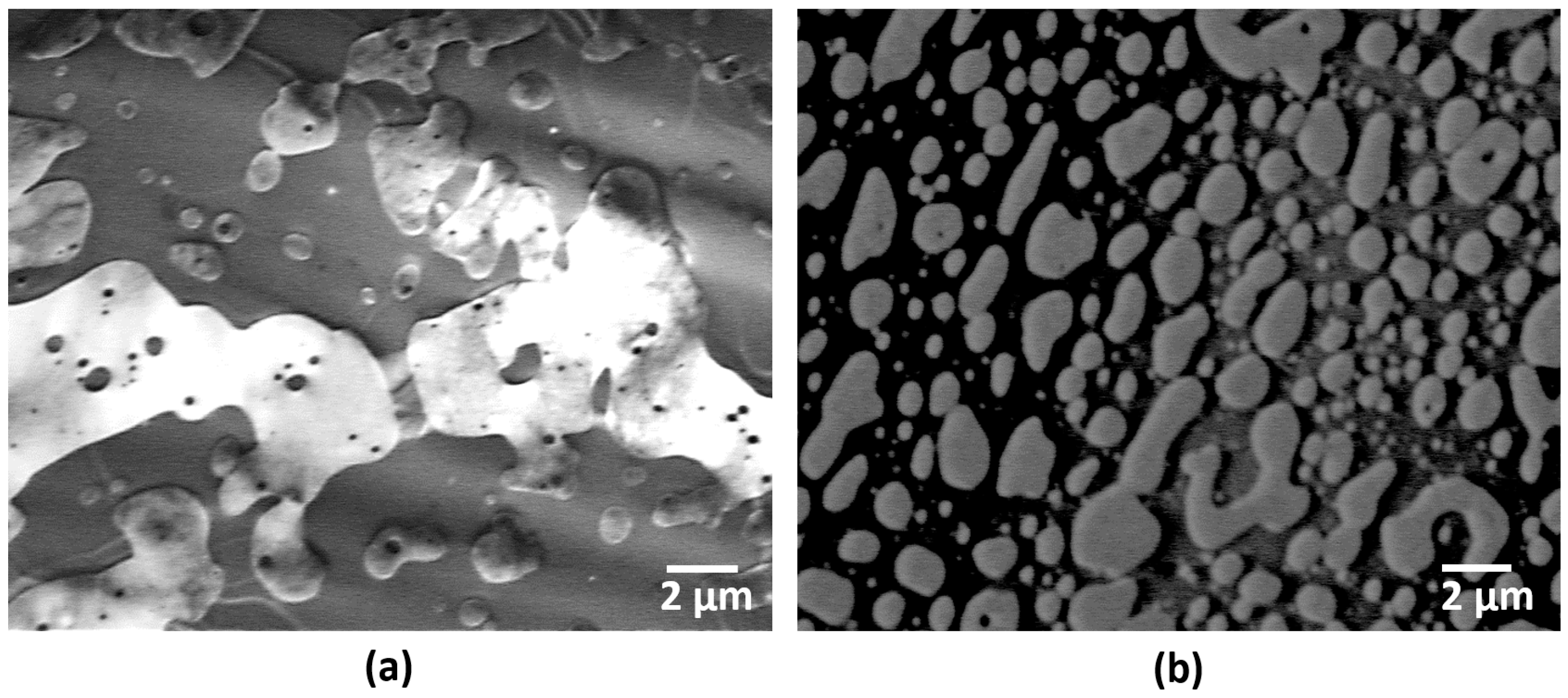
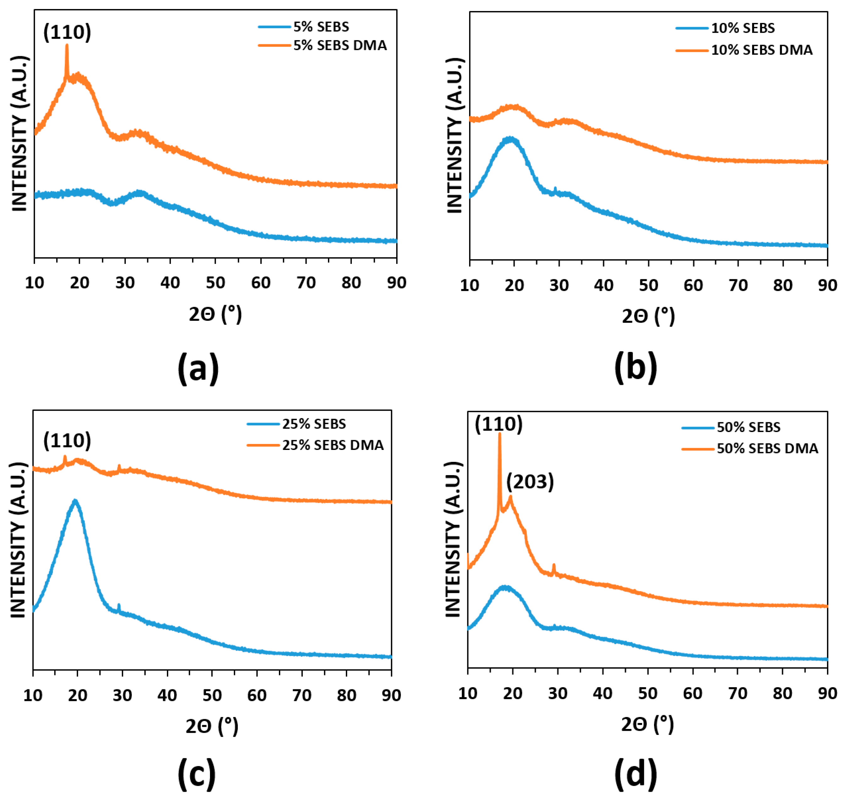
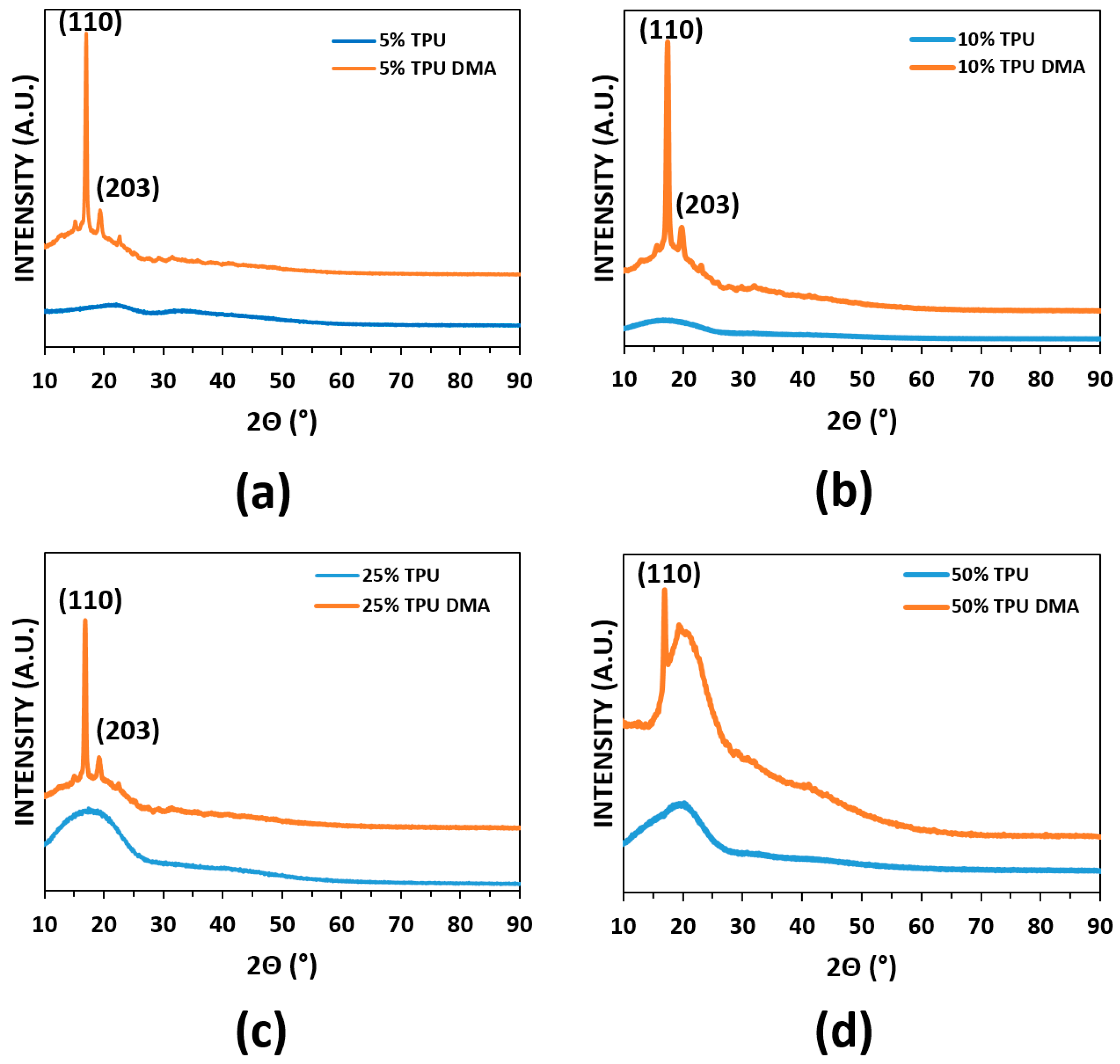
3.1. Initial Characterization of the Blends
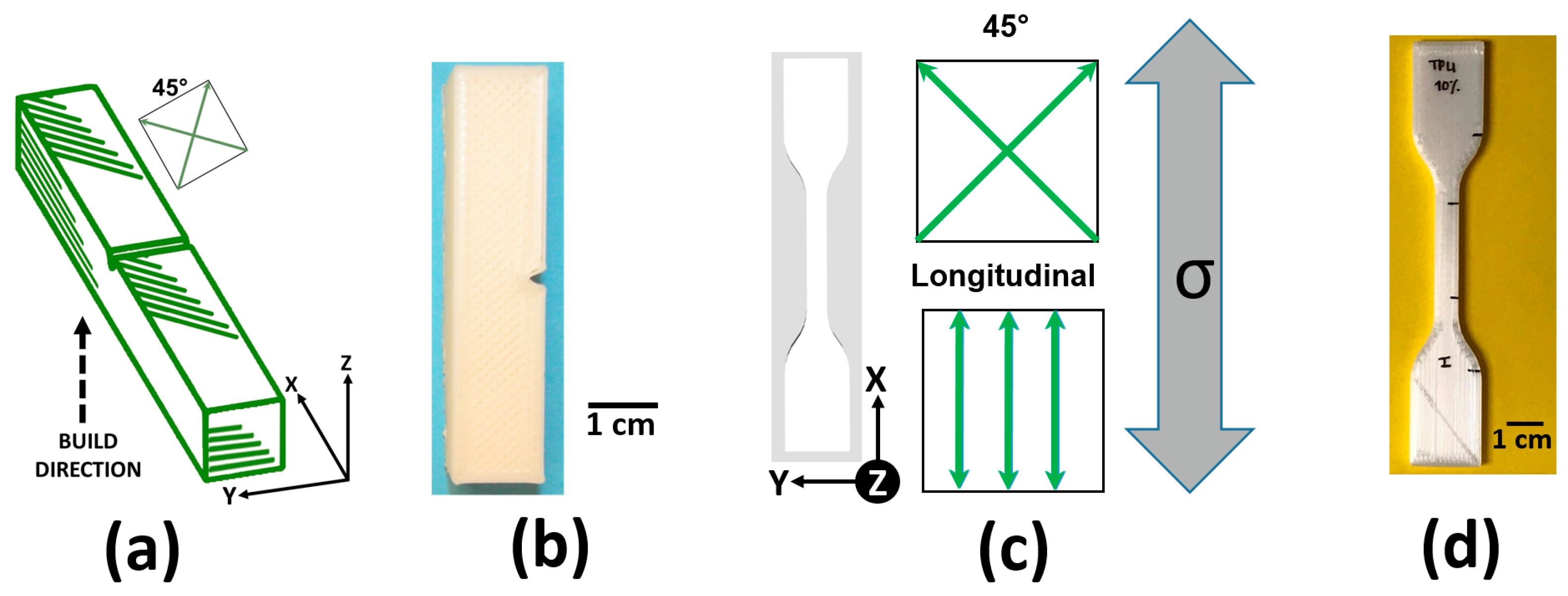
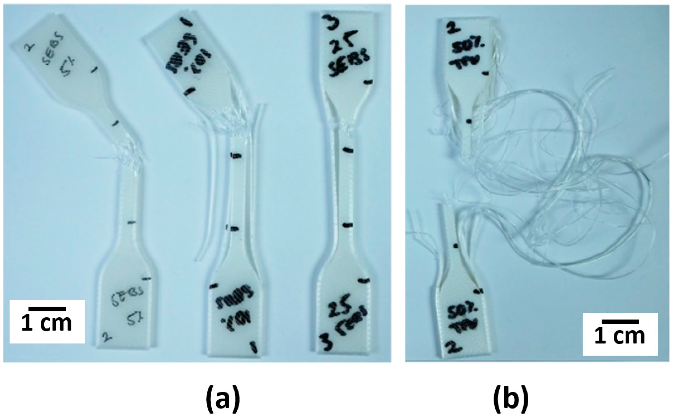
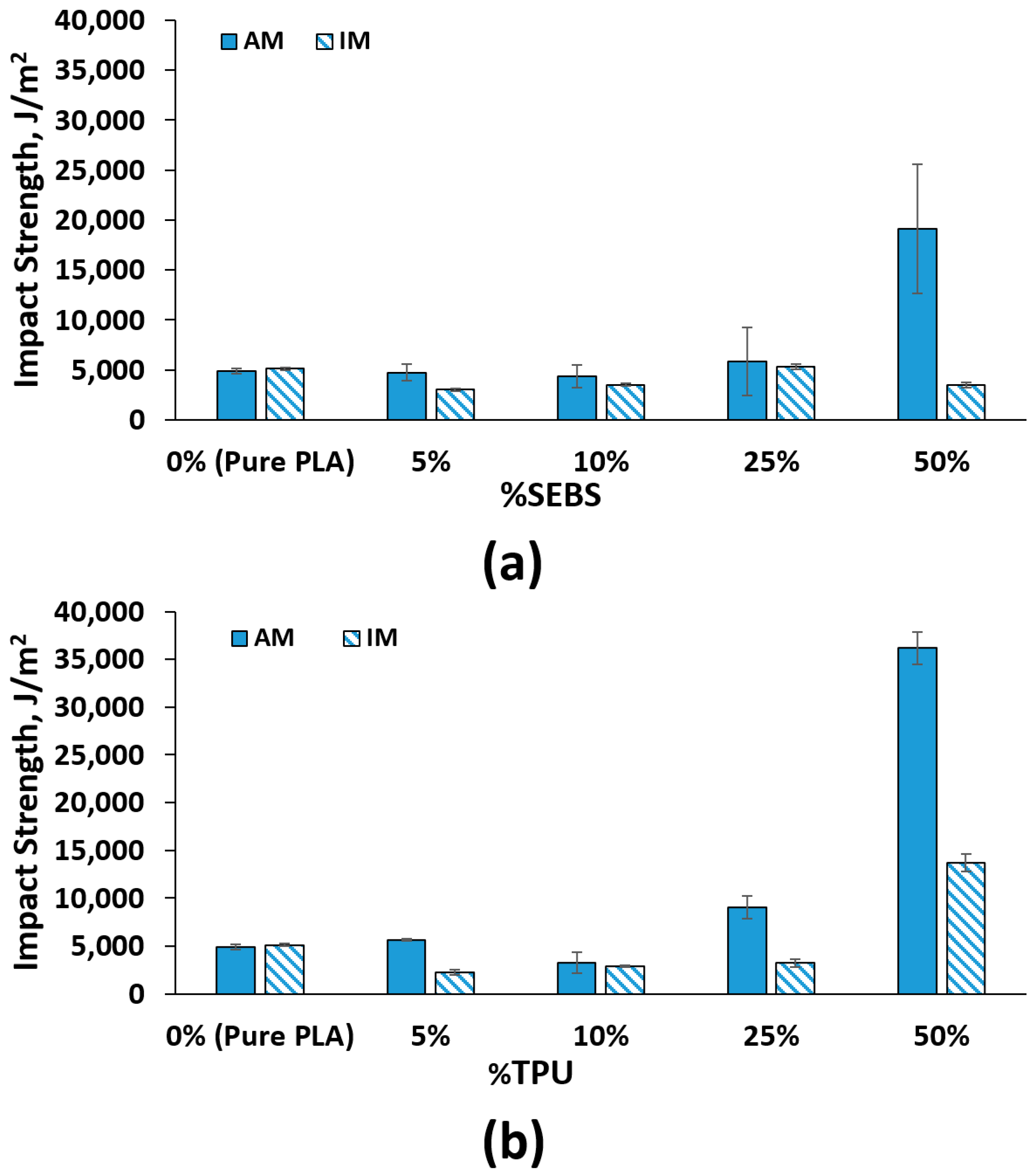
3.2. Mechanical Testing
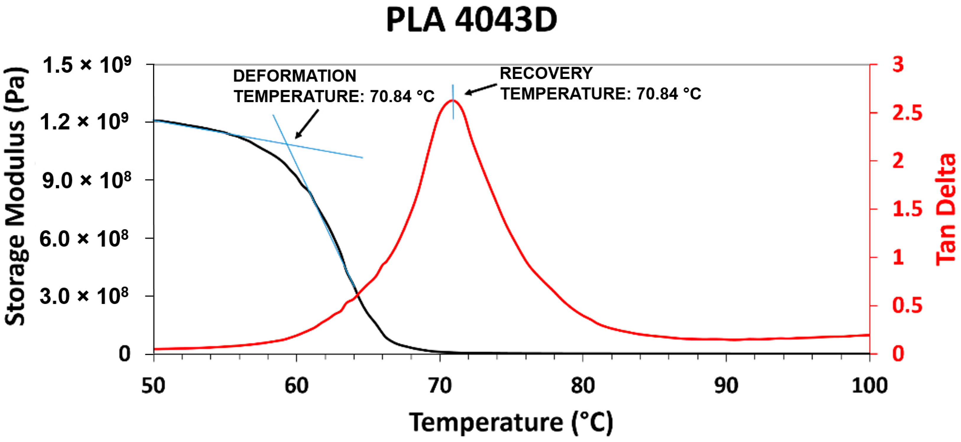
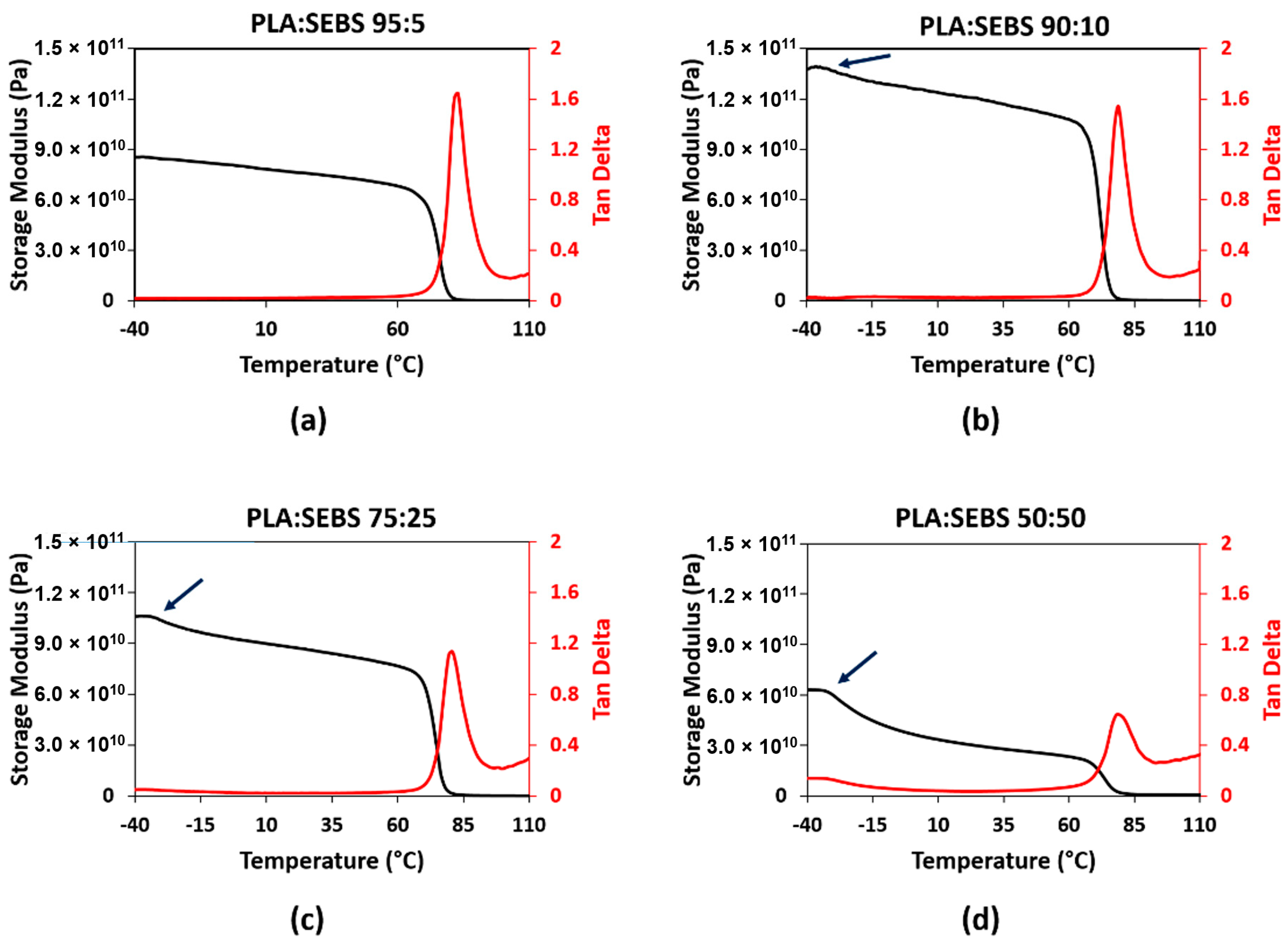
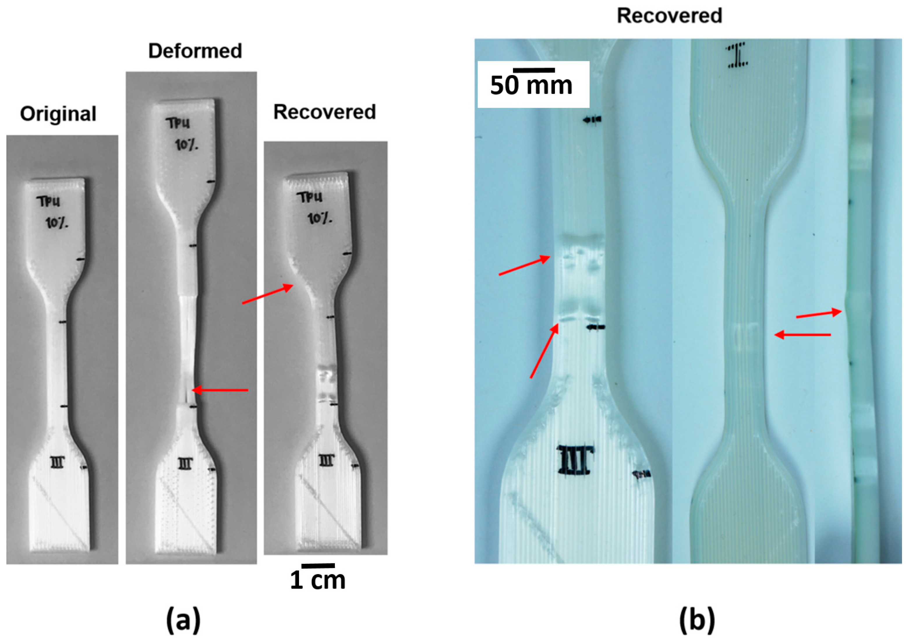
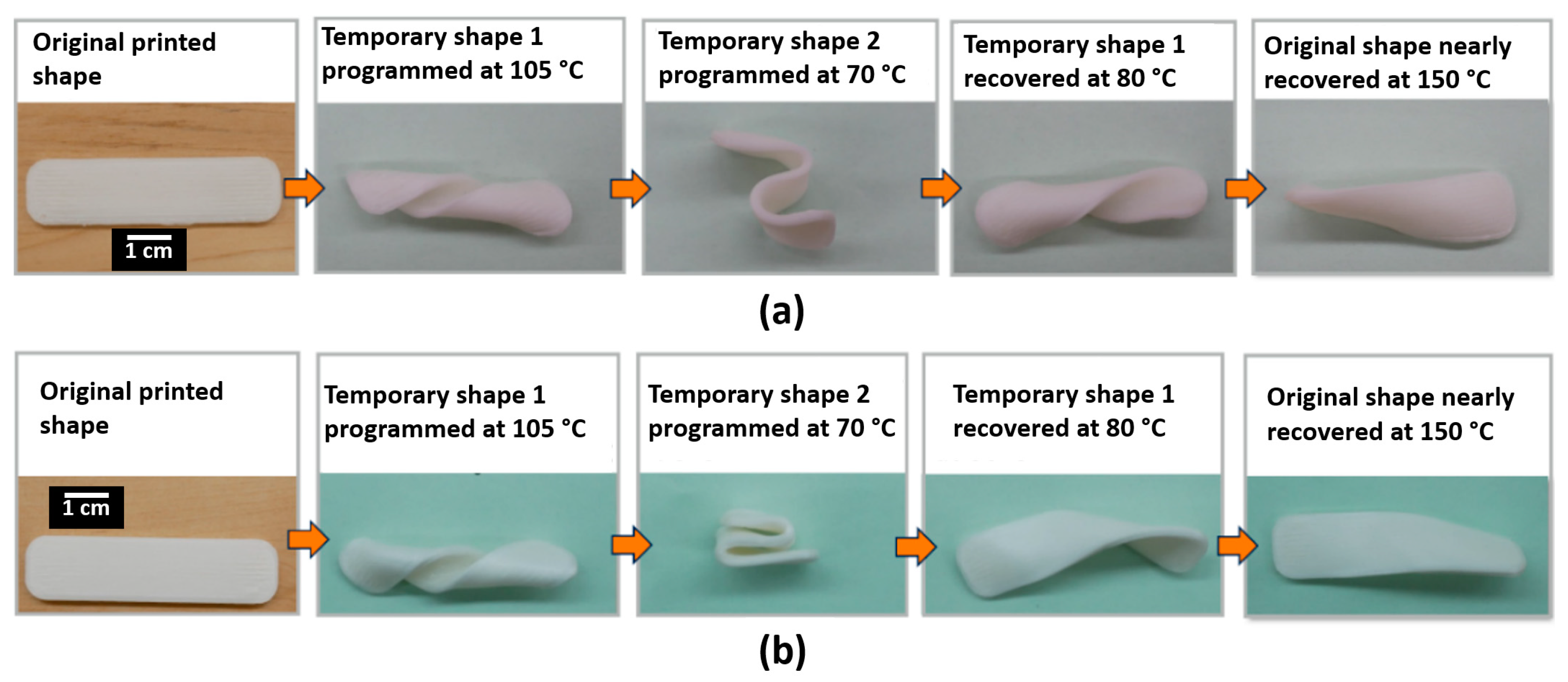
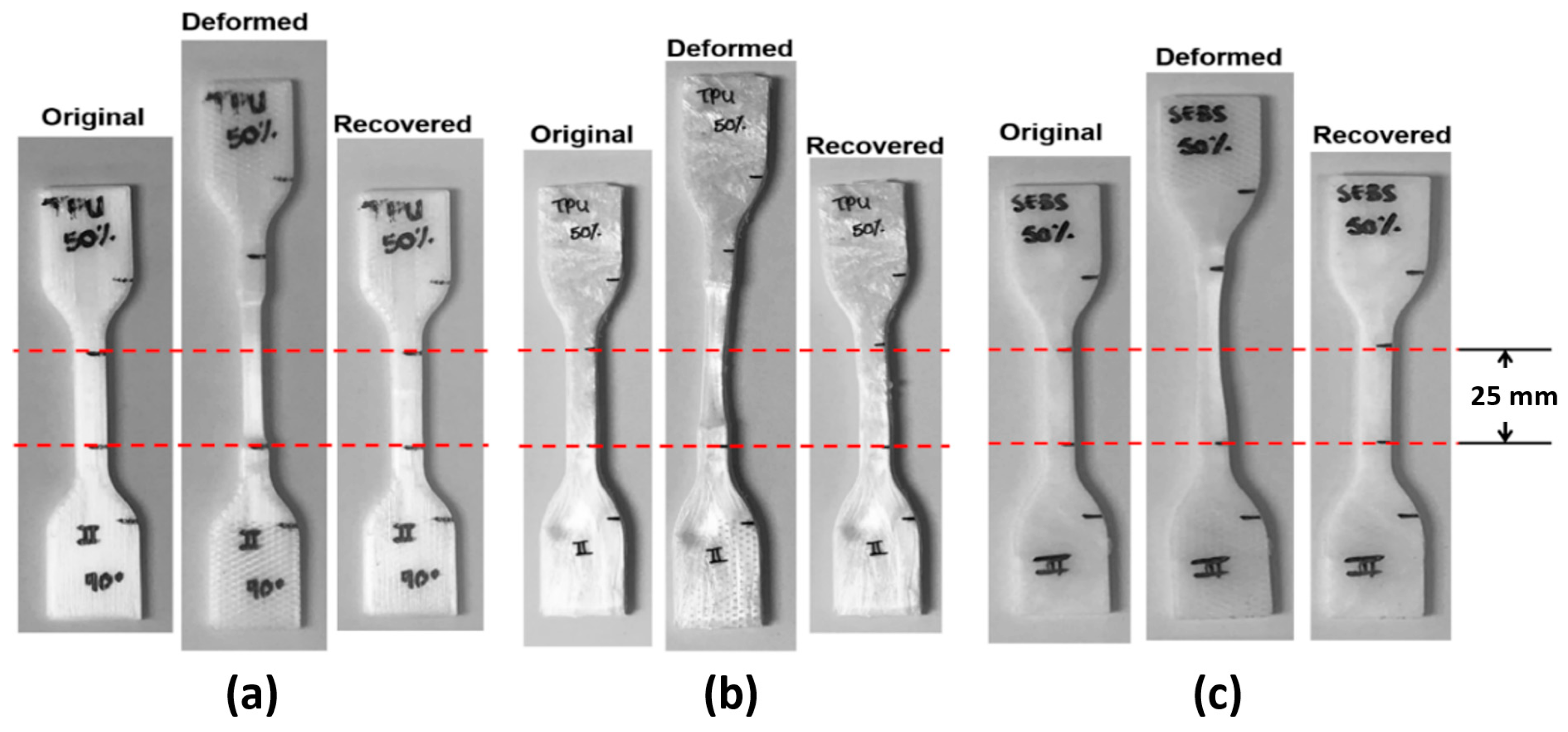
3.3. Shape Memory Characterization
4. Discussion
5. Conclusions
Author Contributions
Funding
Institutional Review Board Statement
Informed Consent Statement
Data Availability Statement
Acknowledgments
Conflicts of Interest
References
- Crump, S.S. Modeling Apparatus for Three-Dimensional Objects, United States Patent US5340433A. 1994. Available online: https://patents.google.com/patent/US5340433A/en (accessed on 30 June 2021).
- Torrado Perez, A.R.; Roberson, D.A.; Wicker, R.B. Fracture Surface Analysis of 3D-Printed Tensile Specimens of Novel ABS-Based Materials. J. Fail. Anal. Prev. 2014, 14, 343–353. [Google Scholar] [CrossRef]
- Berman, B. 3-D Printing: The New Industrial Revolution. Bus. Horiz. 2012, 55, 155–162. [Google Scholar] [CrossRef]
- Chulilla Cano, J.L. The Cambrian Explosion of Popular 3D Printing. Int. J. Interact. Multimed. Artif. Intell. 2011, 1, 30. [Google Scholar] [CrossRef]
- Roberson, D.; Shemelya, C.M.; MacDonald, E.; Wicker, R. Expanding the Applicability of FDM-Type Technologies through Materials Development. Rapid Prototyp. J. 2015, 21, 137–143. [Google Scholar] [CrossRef]
- Quinonez, P.A.; Bermudez, D.; Ugarte-Sanchez, L.; Roberson, D.A. Tailoring Physical Properties of Shape Memory Polymers for FDM-Type Additive Manufacturing. In Proceedings of the 30th Annual International Solid Freeform Fabrication Symposium, TMS, Austin, TX, USA, 12–14 August 2019; pp. 843–855. [Google Scholar]
- Masood, S.H.; Song, W.Q. Development of New Metal/Polymer Materials for Rapid Tooling Using Fused Deposition Modelling. Mater. Des. 2004, 25, 587–594. [Google Scholar] [CrossRef]
- Khatri, B.; Lappe, K.; Habedank, M.; Mueller, T.; Megnin, C.; Hanemann, T. Fused Deposition Modeling of ABS-Barium Titanate Composites: A Simple Route towards Tailored Dielectric Devices. Polymers 2018, 10, 666. [Google Scholar] [CrossRef] [PubMed] [Green Version]
- Haryńska, A.; Kucinska-Lipka, J.; Sulowska, A.; Gubanska, I.; Kostrzewa, M.; Janik, H. Medical-Grade PCL Based Polyurethane System for FDM 3D Printing—Characterization and Fabrication. Materials 2019, 12, 887. [Google Scholar] [CrossRef] [Green Version]
- Schimpf, V.; Max, J.B.; Stolz, B.; Heck, B.; Mülhaupt, R. Semicrystalline Non-Isocyanate Polyhydroxyurethanes as Thermoplastics and Thermoplastic Elastomers and Their Use in 3D Printing by Fused Filament Fabrication. Macromolecules 2019, 52, 320–331. [Google Scholar] [CrossRef]
- Sayanjali, M.; Rezadoust, A.M.; Abbassi Sourki, F. Tailoring Physico-Mechanical Properties and Rheological Behavior of ABS Filaments for FDM via Blending with SEBS TPE. Rapid Prototyp. J. 2020, 26, 1687–1700. [Google Scholar] [CrossRef]
- Zhu, J.; Hu, Y.; Tang, Y.; Wang, B. Effects of Styrene–Acrylonitrile Contents on the Properties of ABS/SAN Blends for Fused Deposition Modeling. J. Appl. Polym. Sci. 2017, 134. [Google Scholar] [CrossRef]
- Word, T.J.; Guerrero, A.; Roberson, D.A. Novel Polymer Materials Systems to Expand the Capabilities of FDMTM-Type Additive Manufacturing. MRS Commun. 2021, 11, 129–145. [Google Scholar] [CrossRef]
- Shemelya, C.M.; Rivera, A.; Perez, A.T.; Rocha, C.; Liang, M.; Yu, X.; Kief, C.; Alexander, D.; Stegeman, J.; Xin, H.; et al. Mechanical, Electromagnetic, and X-Ray Shielding Characterization of a 3D Printable Tungsten–Polycarbonate Polymer Matrix Composite for Space-Based Applications. J. Elec. Materi. 2015, 44, 2598–2607. [Google Scholar] [CrossRef]
- Rocha, C.R.; Perez, A.R.T.; Roberson, D.A.; Shemelya, C.M.; MacDonald, E.; Wicker, R.B. Novel ABS-Based Binary and Ternary Polymer Blends for Material Extrusion 3D Printing. J. Mater. Res. 2014, 29, 1859–1866. [Google Scholar] [CrossRef]
- Siqueiros, J.G.; Schnittker, K.; Roberson, D.A. ABS-Maleated SEBS Blend as a 3D Printable Material. Virtual Phys. Prototyp. 2016, 11, 123–131. [Google Scholar] [CrossRef]
- Yang, Y.; Chen, Y.; Wei, Y.; Li, Y. 3D Printing of Shape Memory Polymer for Functional Part Fabrication. Int. J. Adv. Manuf. Technol. 2016, 84, 2079–2095. [Google Scholar] [CrossRef]
- Raasch, J.; Ivey, M.; Aldrich, D.; Nobes, D.S.; Ayranci, C. Characterization of Polyurethane Shape Memory Polymer Processed by Material Extrusion Additive Manufacturing. Addit. Manuf. 2015, 8, 132–141. [Google Scholar] [CrossRef]
- Pandey, A.; Singh, G.; Singh, S.; Jha, K.; Prakash, C. 3D Printed Biodegradable Functional Temperature-Stimuli Shape Memory Polymer for Customized Scaffoldings. J. Mech. Behav. Biomed. Mater. 2020, 108, 103781. [Google Scholar] [CrossRef]
- Senatov, F.S.; Niaza, K.V.; Zadorozhnyy, M.Y.; Maksimkin, A.V.; Kaloshkin, S.D.; Estrin, Y.Z. Mechanical Properties and Shape Memory Effect of 3D-Printed PLA-Based Porous Scaffolds. J. Mech. Behav. Biomed. Mater. 2016, 57, 139–148. [Google Scholar] [CrossRef]
- Estelle, K.; Blair, D.; Evans, K.; Gozen, B.A. Manufacturing of Smart Composites with Hyperelastic Property Gradients and Shape Memory Using Fused Deposition. J. Manuf. Process. 2017, 28, 500–507. [Google Scholar] [CrossRef]
- Chávez, F.A.; Siqueiros, J.G.; Carrete, I.A.; Delgado, I.L.; Ritter, G.W.; Roberson, D.A. Characterisation of Phases and Deformation Temperature for Additively Manufactured Shape Memory Polymer Components Fabricated from Rubberised Acrylonitrile Butadiene Styrene. Virtual Phys. Prototyp. 2019, 14, 188–202. [Google Scholar] [CrossRef]
- Lai, S.-M.; Lan, Y.-C. Shape Memory Properties of Melt-Blended Polylactic Acid (PLA)/Thermoplastic Polyurethane (TPU) Bio-Based Blends. J. Polym. Res. 2013, 20, 140. [Google Scholar] [CrossRef]
- Memarian, F.; Fereidoon, A.; Ghorbanzadeh Ahangari, M. Effect of Acrylonitrile Butadiene Styrene on the Shape Memory, Mechanical, and Thermal Properties of Thermoplastic Polyurethane. J. Vinyl Addit. Technol. 2018, 24, E96–E104. [Google Scholar] [CrossRef]
- Alan Schoener, C.; Bell Weyand, C.; Murthy, R.; Ann Grunlan, M. Shape Memory Polymers with Silicon -Containing Segments. J. Mater. Chem. 2010, 20, 1787–1793. [Google Scholar] [CrossRef]
- Yang, W.G.; Lu, H.; Huang, W.M.; Qi, H.J.; Wu, X.L.; Sun, K.Y. Advanced Shape Memory Technology to Reshape Product Design, Manufacturing and Recycling. Polymers 2014, 6, 2287–2308. [Google Scholar] [CrossRef]
- Quiñonez, P. Tailoring Physical Properties of Shape Memory Polymers For FDM-Type Additive Manufacturing. Master’s Thesis, University of Texas at El Paso, El Paso, TX, USA, 2019. [Google Scholar]
- Peng, P.; Shi, B.; Jia, L.; Li, B. Relationship between Hansen Solubility Parameters of ABS and Its Homopolymer Components of PAN, PB, and PS. J. Macromol. Sci. Part B 2010, 49, 864–869. [Google Scholar] [CrossRef]
- Wu, P.; Qi, S.; Liu, N.; Deng, K.; Nie, H. Investigation of Thermodynamic Properties of SIS, SEBS, and Naphthenic Oil by Inverse Gas Chromatography. J. Elastomers Plast. 2011, 43. [Google Scholar] [CrossRef]
- Siemann, U. The Solubility Parameter of Poly(Dl-Lactic Acid). Eur. Polym. J. 1992, 28, 293–297. [Google Scholar] [CrossRef]
- Wang, C.; Kou, B.; Hang, Z.; Zhao, X.; Lu, T.; Wu, Z.; Zhang, J.-P. Tunable shape recovery progress of thermoplastic polyurethane by solvents. Pigment Resin Technol. 2018, 47, 47–54. [Google Scholar] [CrossRef]
- Pantoja, M.; Jian, P.-Z.; Cakmak, M.; Cavicchi, K.A. Shape Memory Properties of Polystyrene- Block -Poly(Ethylene- Co -Butylene)- Block -Polystyrene (SEBS) ABA Triblock Copolymer Thermoplastic Elastomers. ACS Appl. Polym. Mater. 2019, 1, 414–424. [Google Scholar] [CrossRef]
- Zhang, Q.; Hua, W.; Feng, J. A Facile Strategy to Fabricate Multishape Memory Polymers with Controllable Mechanical Properties. Macromol. Rapid Commun. 2016, 37, 1262–1267. [Google Scholar] [CrossRef] [PubMed]
- Cavicchi, K.A. Shape Memory Polymers from Blends of Elastomers and Small Molecule Additives. Macromol. Symp. 2015, 358, 194–201. [Google Scholar] [CrossRef]
- Zhang, W.; Chen, L.; Zhang, Y. Surprising Shape-Memory Effect of Polylactide Resulted from Toughening by Polyamide Elastomer. Polymer 2009, 50, 1311–1315. [Google Scholar] [CrossRef]
- Jiang, J.; Su, L.; Zhang, K.; Wu, G. Rubber-Toughened PLA Blends with Low Thermal Expansion. J. Appl. Polym. Sci. 2013, 128, 3993–4000. [Google Scholar] [CrossRef]
- Hashima, K.; Nishitsuji, S.; Inoue, T. Structure-Properties of Super-Tough PLA Alloy with Excellent Heat Resistance. Polymer 2010, 51, 3934–3939. [Google Scholar] [CrossRef]
- Vega, V.; Clements, J.; Lam, T.; Abad, A.; Fritz, B.; Ula, N.; Es-Said, O.S. The Effect of Layer Orientation on the Mechanical Properties and Microstructure of a Polymer. J. Materi. Eng. Perform. 2011, 20, 978–988. [Google Scholar] [CrossRef]
- Torrado, A.R.; Shemelya, C.M.; English, J.D.; Lin, Y.; Wicker, R.B.; Roberson, D.A. Characterizing the Effect of Additives to ABS on the Mechanical Property Anisotropy of Specimens Fabricated by Material Extrusion 3D Printing. Addit. Manuf. 2015, 6, 16–29. [Google Scholar] [CrossRef]
- Torrado, A.R.; Roberson, D.A. Failure Analysis and Anisotropy Evaluation of 3D-Printed Tensile Test Specimens of Different Geometries and Print Raster Patterns. J. Fail. Anal. Preven. 2016, 16, 154–164. [Google Scholar] [CrossRef]
- Es-Said, O.S.; Foyos, J.; Noorani, R.; Mendelson, M.; Marloth, R.; Pregger, B.A. Effect of Layer Orientation on Mechanical Properties of Rapid Prototyped Samples. Mater. Manuf. Process. 2000, 15, 107–122. [Google Scholar] [CrossRef]
- Bermudez, D.; Quiñonez, P.A.; Vasquez, E.J.; Carrete, I.A.; Word, T.J.; Roberson, D.A. A Comparison of the Physical Properties of Two Commercial 3D Printing PLA Grades. Virtual Phys. Prototyp. 2021, 16, 178–195. [Google Scholar] [CrossRef]
- ASTM D638, Test Method for Tensile Properties of Plastics; ASTM International: West Conshohocken, PA, USA, 2021.
- ASTM D256, Test Methods for Determining the Izod Pendulum Impact Resistance of Plastics; ASTM International: West Conshohocken, PA, USA, 2018.
- ASTM D4065 Practice for Plastics: Dynamic Mechanical Properties: Determination and Report of Procedures; ASTM International: West Conshohocken, PA, USA, 2020.
- Roberson, D.A.; Torrado Perez, A.R.; Shemelya, C.M.; Rivera, A.; MacDonald, E.; Wicker, R.B. Comparison of Stress Concentrator Fabrication for 3D Printed Polymeric Izod Impact Test Specimens. Addit. Manuf. 2015, 7, 1–11. [Google Scholar] [CrossRef]
- Brostow, W.; Chiu, R.; Kalogeras, I.M.; Vassilikou-Dova, A. Prediction of Glass Transition Temperatures: Binary Blends and Copolymers. Mater. Lett. 2008, 62, 3152–3155. [Google Scholar] [CrossRef]
- Tabi, T.; Sajo, I.E.; Szabo, F.; Luyt, A.S.; Kovacs, J.G. Crystalline Structure of Annealed Polylactic Acid and Its Relation to Processing. Express Polym. Lett. 2010, 4, 659–668. [Google Scholar] [CrossRef]


| Material System | PLA:TPU | PLA:SEBS | ||||||
|---|---|---|---|---|---|---|---|---|
| Ratio | 5:95 | 10:90 | 25:75 | 50:50 | 5:95 | 10:90 | 25:75 | 50:50 |
| Nozzle Temp. (°C) | 205 | 212 | 225 | 250 | 205 | 210 | 225 | 260 |
| Bed Temp. (°C) | 60 | 60 | 60 | 60 | 60 | 60 | 60 | 60 |
| Printing Speed (mm/s) | 30 | 30 | 30 | 30 | 30 | 30 | 30 | 30 |
| Material System | PLA:TPU | PLA:SEBS | ||||||
|---|---|---|---|---|---|---|---|---|
| Ratio | 5:95 | 10:90 | 25:75 | 50:50 | 5:95 | 10:90 | 25:75 | 50:50 |
| Injection Temp. (°C) | 190 | 190 | 200 | 200 | 190 | 190 | 200 | 200 |
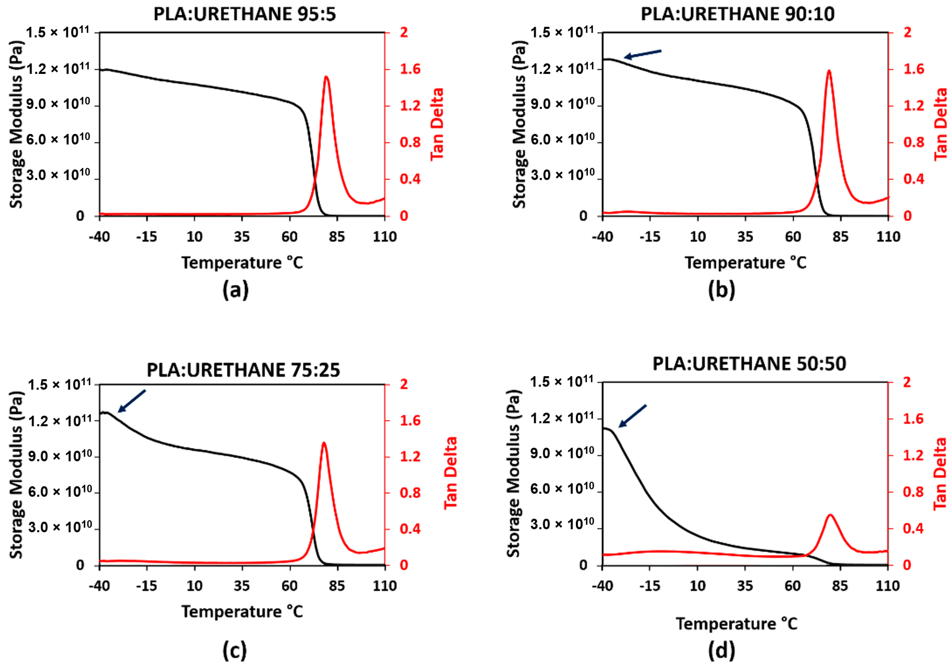
| Blend | Glassy Onset Temp. 1 (°C) | Glassy Onset Temp. 2 (°C) | Max tan δ | Max tan δ Temp. (°C) | Calculated Tg (°C) |
|---|---|---|---|---|---|
| PURE PLA | N/A | 60 | 2.63 | 71 | -- |
| SEBS 5% | N/A | 70 | 1.65 | 81 | 53.00 |
| SEBS 10% | −35 | 70 | 1.54 | 80 | 46.30 |
| SEBS 25% | −34 | 70 | 1.14 | 80 | 27.73 |
| SEBS 50% | −33 | 68 | 0.64 | 78 | 1.17 |
| TPU 5% | N/A | 67 | 1.51 | 77 | 55.63 |
| TPU 10% | −35 | 66 | 1.59 | 77 | 51.37 |
| TPU 25% | −34 | 66 | 1.35 | 77 | 39.22 |
| TPU 50% | −37 | 68 | 0.55 | 77 | 20.89 |
| Blend | Manufacturing Method | Rf (%) | σ | Rr (%) | σ | SMI (%) | σ | Sample Size (n) |
|---|---|---|---|---|---|---|---|---|
| SEBS 50% | IM | 97.17 | 2.35 | 100.00 | 0.00 | 97.17 | 2.35 | 2 |
| TPU 50% | IM | 96.37 | 1.57 | 99.9 | 0.00 | 96.37 | 1.57 | 2 |
| TPU 50% | FFF Long. | 99.34 | 0.00 | 99.9 | 0.00 | 99.34 | 0.62 | 2 |
| TPU 25% | FFF Long. | 96.95 | 2.33 | 100.00 | 0.00 | 96.95 | 0.00 | 2 |
| TPU 10% | FFF Long. | 98.52 | 0.64 | 99.9 | 0.00 | 98.52 | 0.00 | 2 |
| TPU 5% | FFF Long. | 97.48 | 1.82 | 100.00 | 0.00 | 97.48 | 1.82 | 2 |
Publisher’s Note: MDPI stays neutral with regard to jurisdictional claims in published maps and institutional affiliations. |
© 2021 by the authors. Licensee MDPI, Basel, Switzerland. This article is an open access article distributed under the terms and conditions of the Creative Commons Attribution (CC BY) license (https://creativecommons.org/licenses/by/4.0/).
Share and Cite
Quiñonez, P.A.; Ugarte-Sanchez, L.; Bermudez, D.; Chinolla, P.; Dueck, R.; Cavender-Word, T.J.; Roberson, D.A. Design of Shape Memory Thermoplastic Material Systems for FDM-Type Additive Manufacturing. Materials 2021, 14, 4254. https://doi.org/10.3390/ma14154254
Quiñonez PA, Ugarte-Sanchez L, Bermudez D, Chinolla P, Dueck R, Cavender-Word TJ, Roberson DA. Design of Shape Memory Thermoplastic Material Systems for FDM-Type Additive Manufacturing. Materials. 2021; 14(15):4254. https://doi.org/10.3390/ma14154254
Chicago/Turabian StyleQuiñonez, Paulina A., Leticia Ugarte-Sanchez, Diego Bermudez, Paulina Chinolla, Rhyan Dueck, Truman J. Cavender-Word, and David A. Roberson. 2021. "Design of Shape Memory Thermoplastic Material Systems for FDM-Type Additive Manufacturing" Materials 14, no. 15: 4254. https://doi.org/10.3390/ma14154254
APA StyleQuiñonez, P. A., Ugarte-Sanchez, L., Bermudez, D., Chinolla, P., Dueck, R., Cavender-Word, T. J., & Roberson, D. A. (2021). Design of Shape Memory Thermoplastic Material Systems for FDM-Type Additive Manufacturing. Materials, 14(15), 4254. https://doi.org/10.3390/ma14154254