
Microstructure and Properties of SUS304 Stainless Steel Joints Brazed with Electrodeposited Ni-Cr-P Alloy Coatings

 , ,
, ,
Abstract
:1. Introduction
2. Materials and Methods
2.1. Materials
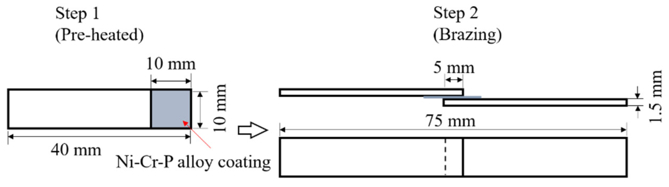
2.2. Brazing Test
2.3. Shear Test
2.4. Microstructure Observation
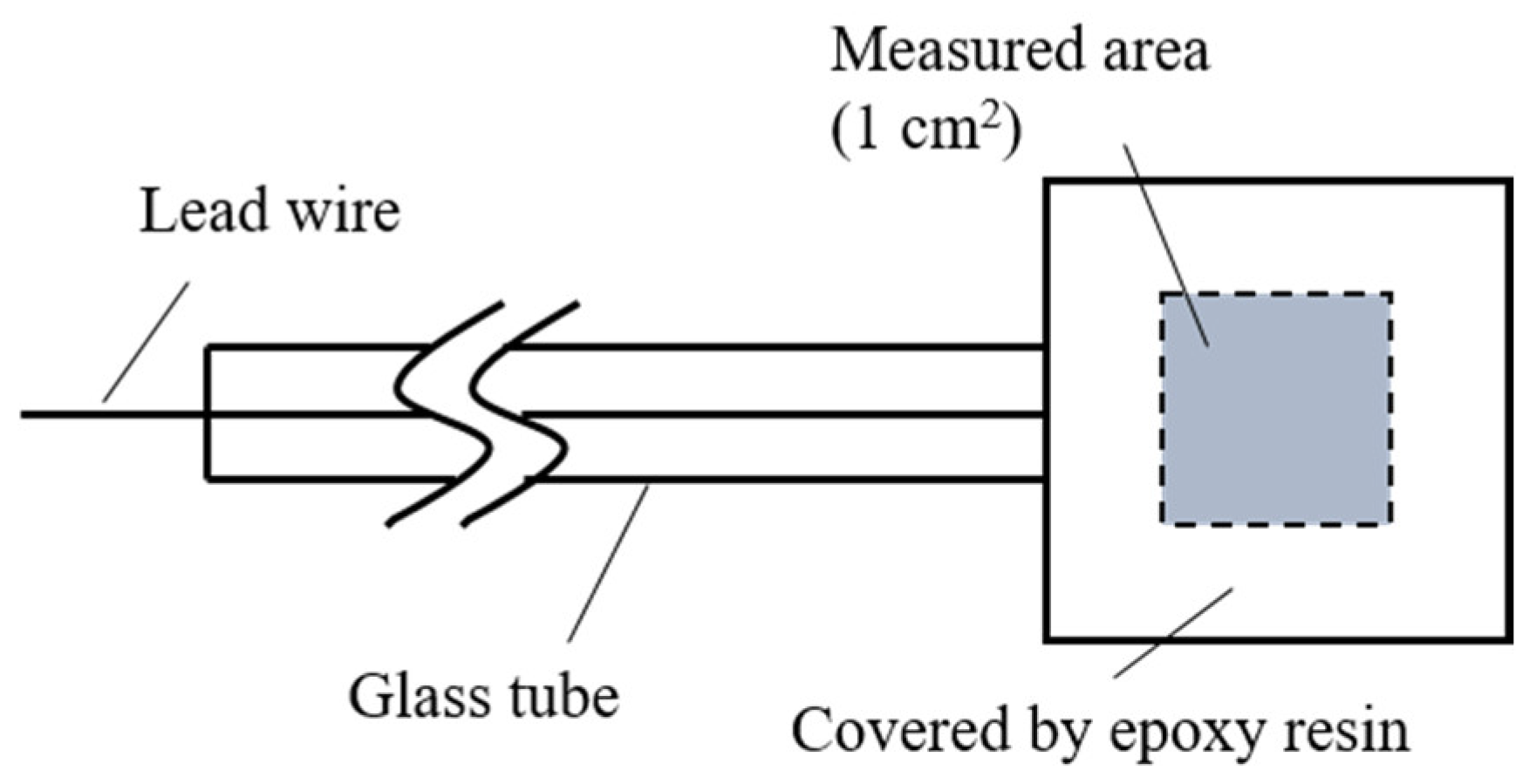
2.5. Electrochemical Analysis
3. Results and Discussion
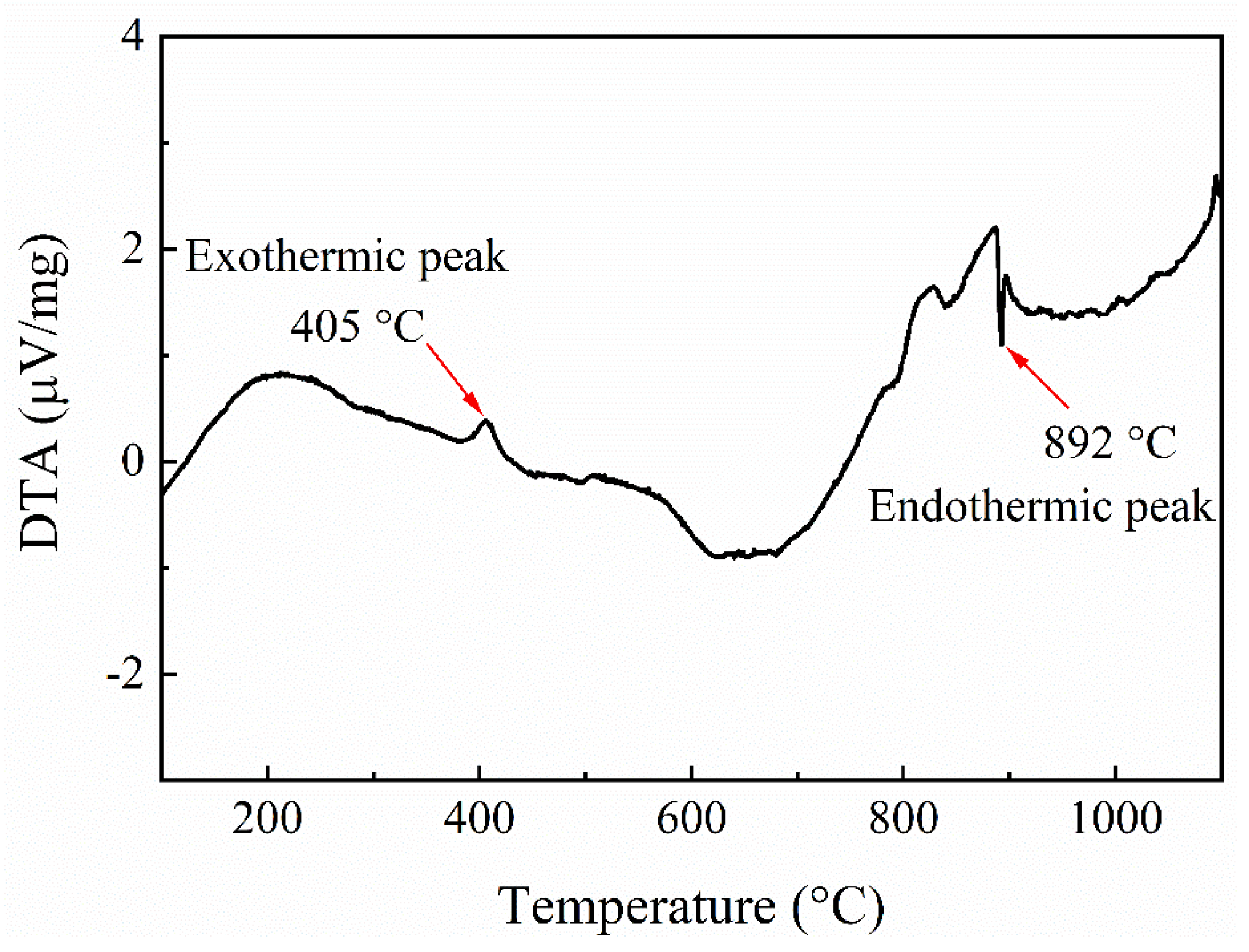
3.1. Properties of Electrodeposited Ni-13.4Cr-11.6P Alloy Coating
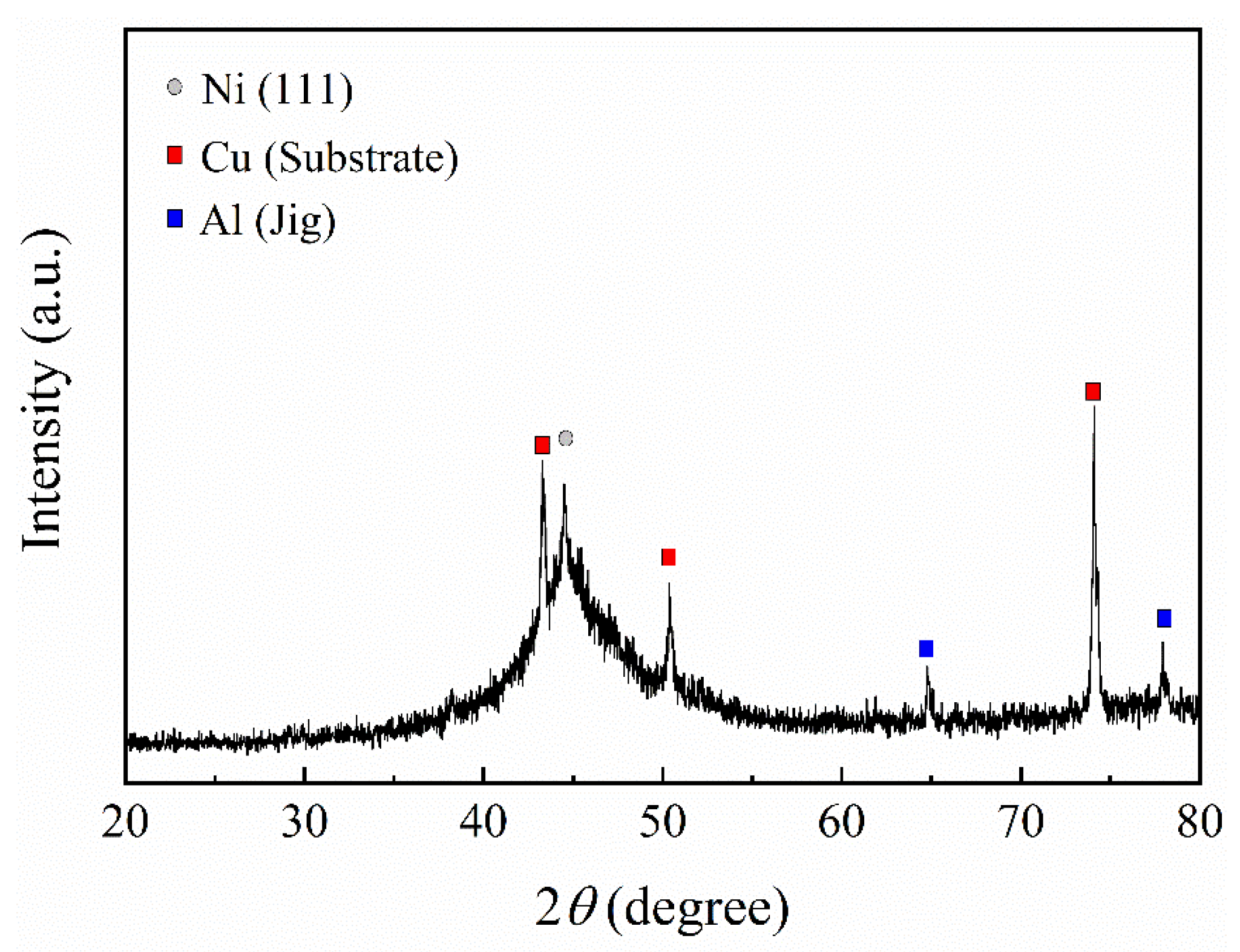
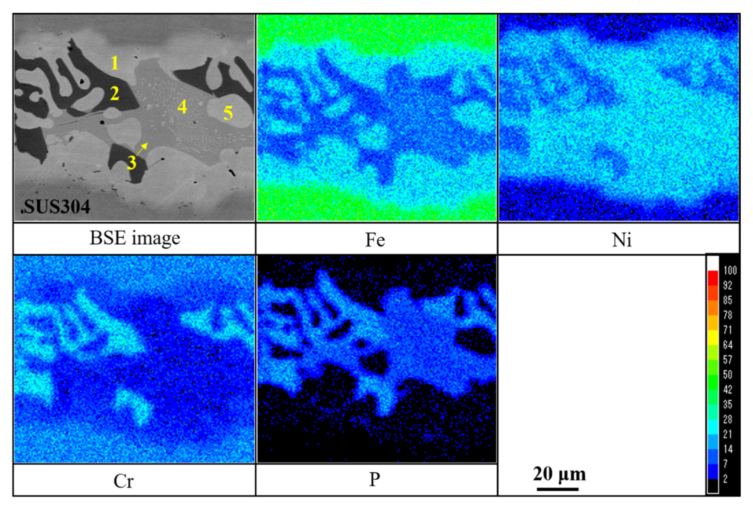
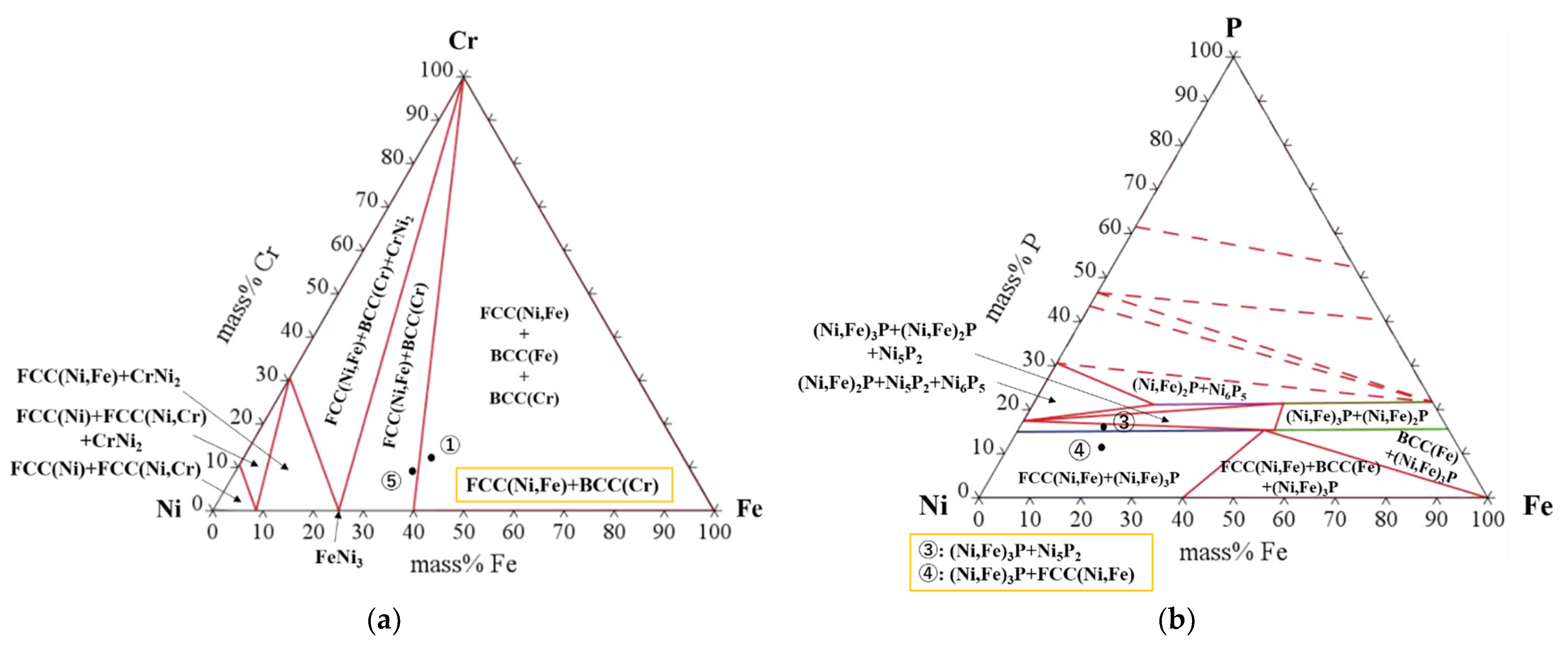
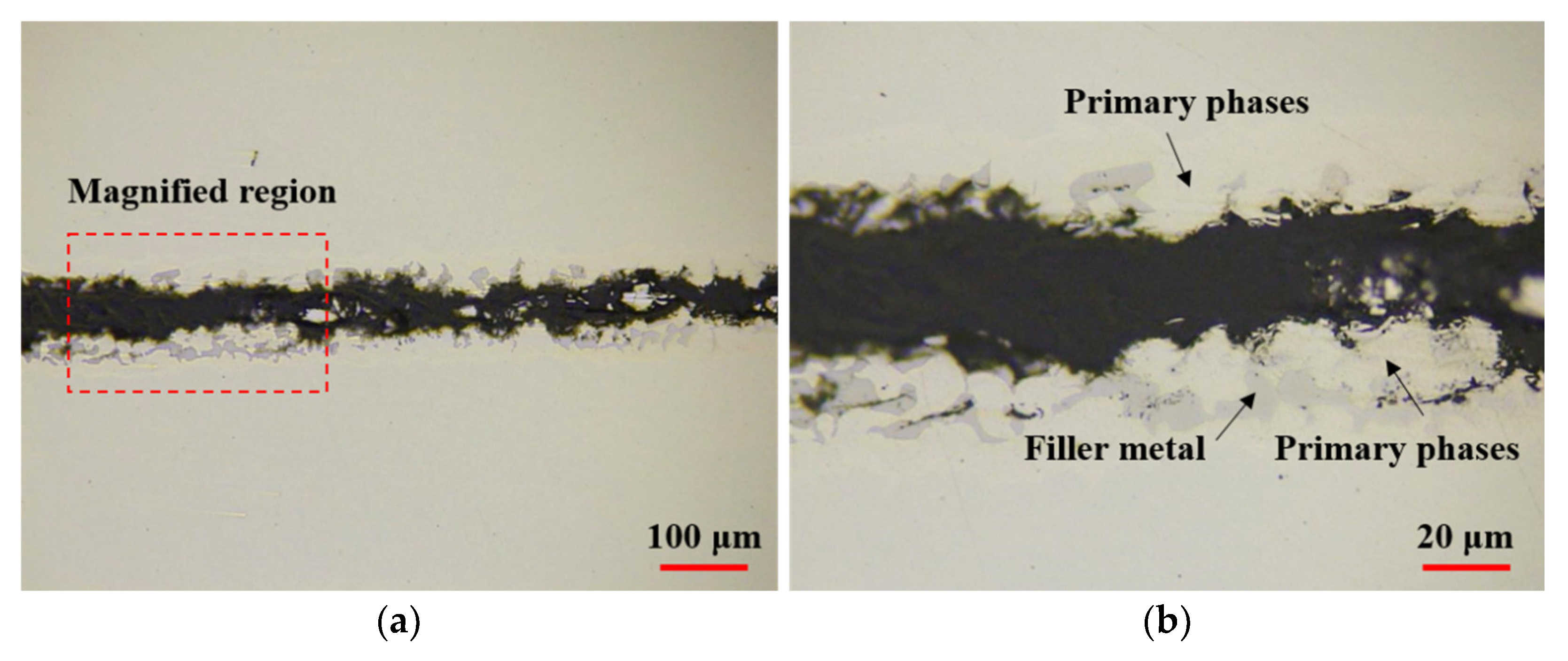
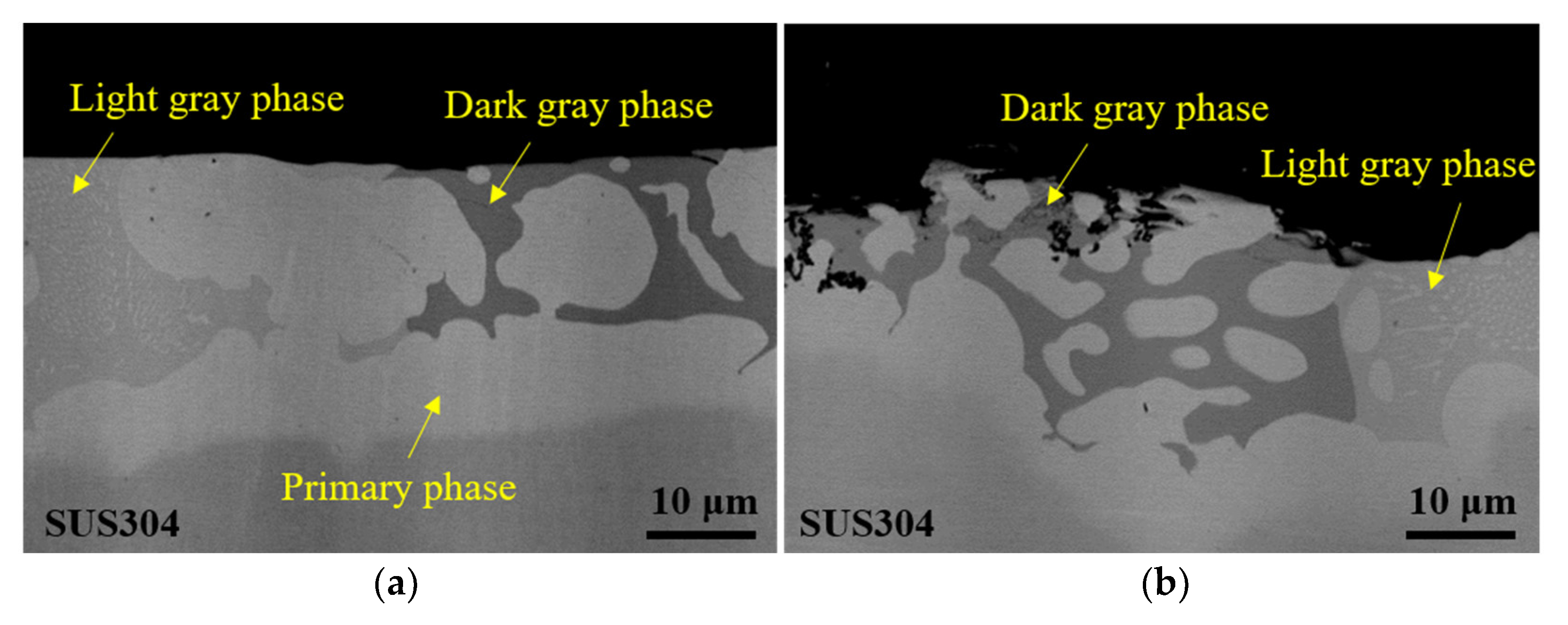
3.2. Microstructure Analysis of Brazed Joint
3.3. Shear Strength
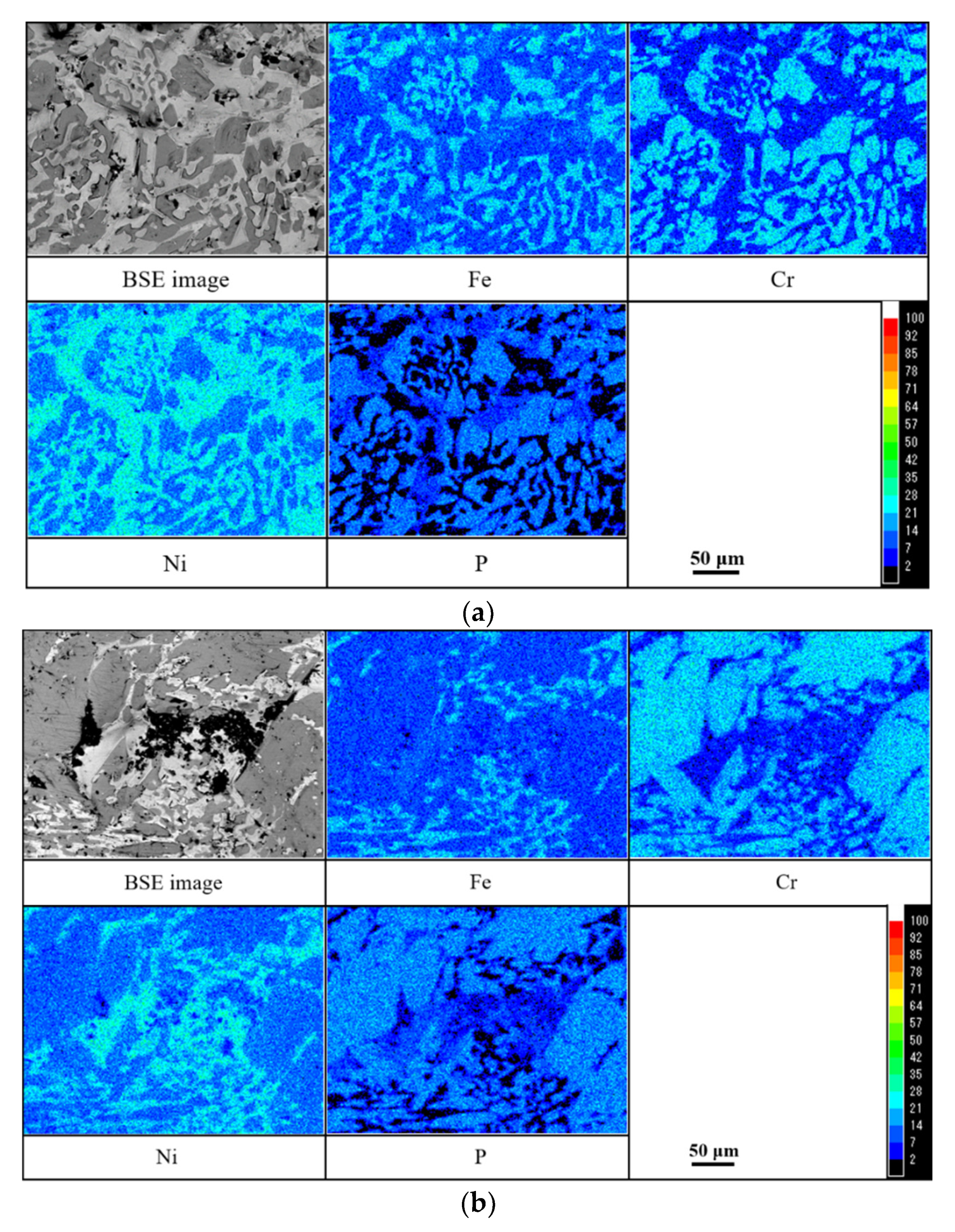
3.4. Fracture Mode of Brazed Joint
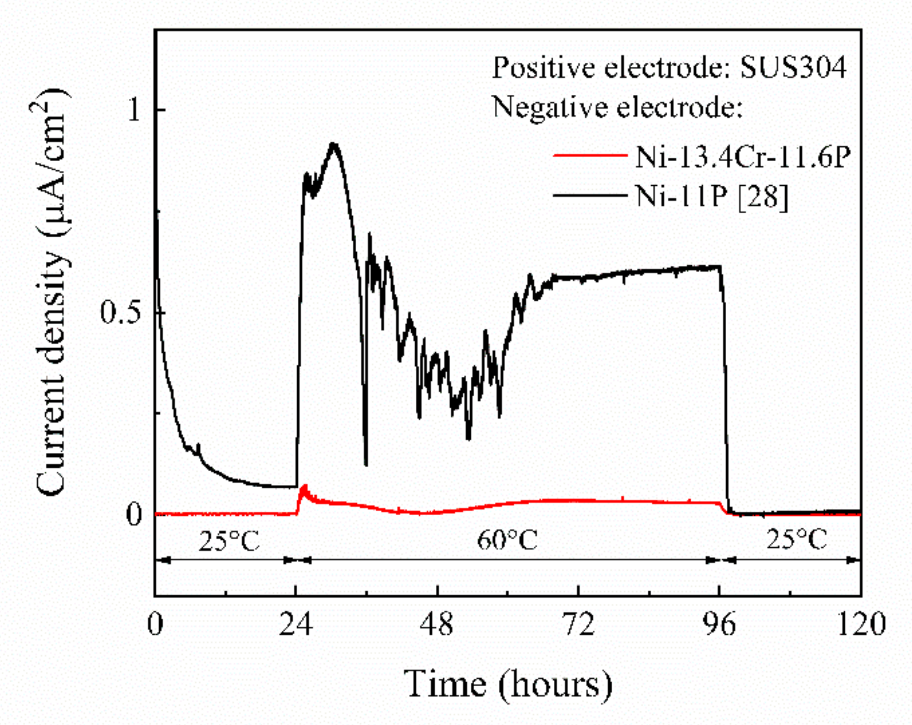
3.5. Corrosion Behaviors
4. Conclusions
Author Contributions
Funding
Institutional Review Board Statement
Informed Consent Statement
Data Availability Statement
Conflicts of Interest
References
- Kazakov, N.F. Diffusion Bonding of Materials; Elsevier: Oxford, UK, 1985; ISBN 978-1483118130. [Google Scholar]
- Fang, Y.; Jiang, X.; Mo, D.; Zhu, D.; Luo, Z. A review on dissimilar metals’ welding methods and mechanisms with interlayer. Int. J. Adv. Manuf. Technol. 2019, 120, 2845–2863. [Google Scholar] [CrossRef]
- Gietzelt, T.; Toth, V.; Huell, A.; Messerschmidt, F.; Dittmeyer, R. Systematic investigation of the diffusion welding behavior of the austenitic stainless steel 304 (1.4301). Adv. Eng. Mater. 2014, 16, 1381–1390. [Google Scholar] [CrossRef]
- Zorc, B.; Kosec, L. Comparison of brazed joints made with BNi–1 and BNi–7 nickel–base brazing alloys. Rev. Metal. 2000, 36, 100–107. [Google Scholar] [CrossRef] [Green Version]
- Way, M.; Willingham, J.; Goodall, R. Brazing filler metals. Int. Mater. Rev. 2020, 65, 257–285. [Google Scholar] [CrossRef]
- Farzam, A.; Seyyed, E.M.; Amirhossein, S. Effect of bonding time on microstructure and mechanical properties of diffusion brazed IN–939. J. Mater. Process. Technol. 2019, 265, 219–229. [Google Scholar]
- Abdulaziz, A.; Nils, H. Diffusion Bonding and Transient Liquid Phase (TLP) Bonding of Type 304 and 316 Austenitic Stainless steel–A Review of Similar and Dissimilar Material Joints. Metals 2020, 10, 613. [Google Scholar]
- Jiang, W.; Gong, J.; Tu, S.T. Effect of brazing temperature on tensile strength and microstructure for a stainless steel plate–fin structure. Mater. Des. 2011, 32, 736–742. [Google Scholar] [CrossRef]
- Park, D.Y.; Lee, S.K.; Kim, J.K.; Lee, S.N.; Park, S.J.; Oh, Y.J. Image processing–based analysis of interfacial phases in brazed stainless steel with Ni–based filler metal. Mater. Charact. 2017, 13, 278–284. [Google Scholar] [CrossRef]
- Abdolvand, R.; Atapour, M.; Shamanian, M.; Allafchian, A. The effect of bonding time on the microstructure and mechanical properties of transient liquid phase bonding between SAF 207 and AISI 304. J. Manuf. Process 2017, 25, 172–180. [Google Scholar] [CrossRef]
- Ou, C.L.; Liaw, D.W.; Du, Y.C.; Shiue, R.K. Brazing of 422 stainless steel using the AWS classification BNi–2 Braze alloy. J. Mater. Sci. 2006, 41, 6353–6361. [Google Scholar] [CrossRef]
- Ruiz-Vargas, J.; Siredey-Schwaller, N.; Bocher, P.; Hazotte, A. First melting stages during isothermal brazing, of Ni/BNi–2 couples. J. Mater. Process. Technol. 2013, 213, 2074–2080. [Google Scholar] [CrossRef]
- Shi, H.; Yu, Z.; Cho, J. A study on the microstructure and properties of brazing joint for Cr18–Ni8 steel using a BNi–7+9%Cu mixed filler metal. Vacuum 2018, 151, 226–232. [Google Scholar]
- Zhang, H.; Zhu, W.; Zhang, T.; Guo, C.; Ran, X. Effect of Brazing Temperature on Microstructure and Mechanical Property of High Nitrogen Austenitic Stainless Steel Joints Brazed with Ni–Cr–P Filler. ISIJ Int. 2019, 59, 1–5. [Google Scholar] [CrossRef] [Green Version]
- Li, G.; Zhang, P.; Shi, H.; Yu, Z. Microstructure and properties of Cr18–Ni8 steel joints brazed with BNi7+3%Cu composite solder. Vacuum 2018, 148, 303–311. [Google Scholar] [CrossRef]
- Wang, J.; Wang, J.; Li, Y.; Zhang, D. Microstructure and Shear Strength in Brazing Joint of Mo–Cu Composite with 304 Stainless Steel by Ni–Cr–P Filler Metal. High Temp. Mater. Proc. 2015, 34, 347–351. [Google Scholar] [CrossRef]
- Wu, N.; Li, Y.; Wang, J.; Puchkov, U.A. Vacuum brazing of super–Ni/NiCr laminated composite to Cr18–Ni8 steel with NiCrP filler metal. J. Mater. Process. Technol. 2012, 212, 794–800. [Google Scholar] [CrossRef]
- Shohji, I.; Arai, S.; Kano, N.; Otomo, N.; Uenishi, M. Development of Cu brazing sheet with Cu–P composite plating. Key Eng. Mater. 2007, 353–358, 2025–2028. [Google Scholar] [CrossRef]
- Piotr, J.; Malgorzata, G.; Wojciech, D.; Justyna, C.G. Application of SiC particles coated with a protective Ni layer for production of Ni/SiC co–electrodeposited composite coatings with enhanced tribological properties. Ceram. Int. 2019, 45, 23540–23547. [Google Scholar]
- Liu, S.B.; Shohji, I.; Iioka, M.; Hashimoto, A.; Hirohashi, J.; Wake, T.; Arai, S. Micro–Brazing of Stainless Steel using Ni–P Alloy Plating. Appl. Sci. 2019, 9, 1094. [Google Scholar] [CrossRef] [Green Version]
- Liu, S.B.; Shohji, I.; Kobayashi, K.; Hirohashi, J.; Wake, T.; Yamamoto, H.; Kamakoshi, Y. Mechanistic Study of Ni–Cr–P Alloy Electrodeposition and Characterization of Deposits. J. Electroanal. Chem. 2021. (under review). [Google Scholar]
- Lelevic, A.; Walsh, F.C. Electrodeposition of Ni–P alloy coatings: A review. Surf. Coat. Technol. 2019, 369, 198–220. [Google Scholar] [CrossRef]
- Pillai, M.; Rajendra, A.; Sharma, A.K. Electrodeposited nickel–phosphorous (Ni–P) alloy coating: An in–depth study of its preparation, properties, and structural transitions. J. Coat. Technol. Res. 2012, 9, 785–797. [Google Scholar] [CrossRef]
- Melo, R.L.; Casciano, P.N.S.; Correia, A.N.; De Lima–Neto, P. Characterization of electrodeposited and heat–treated Ni–Mo–P coatings. J. Braz. Chem. Soc. 2012, 23, 328–334. [Google Scholar] [CrossRef] [Green Version]
- Wolfenden, A.; Kondlapudi, S.K.R. Determination of the mechanical properties of amorphous Ni–Cr–P alloys. J. Mater. Sci. 1993, 28, 1090–1096. [Google Scholar] [CrossRef]
- Lugscheider, E.; Partz, K.D. High Temperature Brazing of Stainless Steel with Nickel–base Filler Metals BNi–2, BNi–5 and BNi–7. Weld. J. 1983, 62, 160–164. [Google Scholar]
- Zhuang, H.; Chen, J.; Lugscheider, E. Wide gap of stainless steels with nickel–base brazing alloys. Weld. World 1986, 24, 200–208. [Google Scholar]
- Anna, H.; Shubin, L.; Ikuo, S.; Tatsuya, K.; Junichiro, H.; Tsunehito, W.; Susumu, A.; Yuichiro, K. Brazing of Stainless Steel Using Electrolytic Ni–P Plating Film and Investigation of Corrosion Behavior. Mater. Sci. Forum 2020, 1016, 522–527. [Google Scholar]
- Masahiro, S.; Shota, N. Electrochemical Behavior of Nickel Brazing Filler Metal BNi–5 in NaCl Solution at High Temperature. Corros. Eng. 2015, 64, 197–200. [Google Scholar]
- Masanori, K. Effect of Trace Elements on Steel Corrosion. Mater. Jpn. 1973, 12, 533–545. [Google Scholar]


| Symbol | Fe | Ni | Cr | S | Si | P | Mn | C |
|---|---|---|---|---|---|---|---|---|
| SUS304 | Bal. | 8.00~10.50 | 18.00~20.00 | ≤0.030 | ≤1.00 | ≤0.045 | ≤2.00 | ≤0.08 |
| - | Ni | Cr | P | O | C | - | - | - |
| Ni-Cr-P | Bal. | 13.4 | 11.6 | 8.5 | 3.4 | - | - | - |
| Composition | Concentration (M) | Deposition Conditions |
|---|---|---|
| CrCl3·6H2O (Chromium Chloride) | 0.4 | Current density (j): 15 A/dm2 pH: 1.8 Bath temperature: 30 °C Total charge: 1215 C/cm2 Anode: Platinum plated titanium mesh Cathode: SUS304 plate (with a plating area of 5 cm2) |
| NiCl2·6H2O (Nickel Chloride) | 0.25 | |
| NaHPO2·H2O (Sodium Hypophosphite) | 0.14 | |
| H2NCH2COOH (Glycine) | 0.5 | |
| NH4Cl (Amonium Chloride) | 0.5 | |
| NaCl (Sodium Chloride) | 0.5 | |
| C6H5Na3O7 (Sodium Citrate) | 0.2 | |
| NaBr (Sodium Bromide) | 0.145 | |
| H3BO3 (Boric Acid) | 0.5 | |
| C7H4NO3SNa·2H2O (Saccharin Sodium) | 0.6 g/L | |
| SDS (Sodium Dodecyl Sulfate) | 0.1 g/L |
| Point | Chemical Compositions (Mass%) | |||
|---|---|---|---|---|
| Ni | Cr | Fe | P | |
| 1 | 50.77 | 11.42 | 37.01 | 0.80 |
| 2 | 28.94 | 34.98 | 14.43 | 21.65 |
| 3 | 58.14 | 7.53 | 18.37 | 15.96 |
| 4 | 59.37 | 6.76 | 22.59 | 11.28 |
| 5 | 53.17 | 9.22 | 36.79 | 0.82 |
| Filler Metal | Sample No. | Shear Strength (MPa) | Ave. (MPa) |
|---|---|---|---|
| Ni-13.4Cr-11.6P | A-1 | 57.0 | 59.0 |
| A-2 | 60.0 | ||
| A-3 | 59.4 | ||
| Ni-11P | B-1 | 54.3 | 47.3 |
| B-2 | 44.7 | ||
| B-3 | 42.8 | ||
| B-4 | 47.3 |
Publisher’s Note: MDPI stays neutral with regard to jurisdictional claims in published maps and institutional affiliations. |
© 2021 by the authors. Licensee MDPI, Basel, Switzerland. This article is an open access article distributed under the terms and conditions of the Creative Commons Attribution (CC BY) license (https://creativecommons.org/licenses/by/4.0/).
Share and Cite
Liu, S.; Shohji, I.; Kobayashi, T.; Osanai, K.; Ando, T.; Hirohashi, J.; Wake, T.; Inoue, K.; Yamamoto, H. Microstructure and Properties of SUS304 Stainless Steel Joints Brazed with Electrodeposited Ni-Cr-P Alloy Coatings. Materials 2021, 14, 4216. https://doi.org/10.3390/ma14154216
Liu S, Shohji I, Kobayashi T, Osanai K, Ando T, Hirohashi J, Wake T, Inoue K, Yamamoto H. Microstructure and Properties of SUS304 Stainless Steel Joints Brazed with Electrodeposited Ni-Cr-P Alloy Coatings. Materials. 2021; 14(15):4216. https://doi.org/10.3390/ma14154216
Chicago/Turabian StyleLiu, Shubin, Ikuo Shohji, Tatsuya Kobayashi, Katsuharu Osanai, Tetsuya Ando, Junichiro Hirohashi, Tsunehito Wake, Katsufumi Inoue, and Hiroki Yamamoto. 2021. "Microstructure and Properties of SUS304 Stainless Steel Joints Brazed with Electrodeposited Ni-Cr-P Alloy Coatings" Materials 14, no. 15: 4216. https://doi.org/10.3390/ma14154216
APA StyleLiu, S., Shohji, I., Kobayashi, T., Osanai, K., Ando, T., Hirohashi, J., Wake, T., Inoue, K., & Yamamoto, H. (2021). Microstructure and Properties of SUS304 Stainless Steel Joints Brazed with Electrodeposited Ni-Cr-P Alloy Coatings. Materials, 14(15), 4216. https://doi.org/10.3390/ma14154216