
Evaluation of Wear Behaviour in Metallic Binders Employed in Diamond Tools for Cutting Stone


Abstract
:1. Introduction
- Diamond Holding Capacity: an attribute of the binder related to the capacity for resisting the continuous impacts/forces/stresses caused by the penetration of the diamond into the stone during cutting, with the objective of avoiding a premature loosening of the particle (i.e., losing a particle that has not reached the end of its expected working life). In general, the diamond holding capacity will be higher the better the mechanical tensile strength conditions in the binder in which the particles are embedded and the higher the boundary adhesion between the binder and the particles.
- Wear resistance: an attribute of the binder, related to its mechanical properties, and that depends on the wear mechanism originated by the cutting process and the class of stone. The relationship between wear resistance and binder properties will differ from case to case (from severe erosive wear mechanisms to adhesive wear).
- (i)
- A mechanical characterization, to establish first selection criteria when designing new tools, especially when it is possible to compare similar processes using equivalent tools with known binder properties. This characterization follows test methodologies that are well established [21].
- (ii)
- A wear characterization, where the binders are tested in comparable situations from those observed in real cutting conditions. For assessing relevant wear parameters related to the cutting processes, to date no works have been observed in the open literature.
2. Materials and Methods
2.1. Powder Sintered Binders and Their Properties
- The density of the binders (ρ) was determined by the Archimedes/water immersion method using an Electronic Densimeter EW-200SG (Alfa Mirage Co., Ltd., Osaka, Japan).
- Vickers hardness (HV) was determined using the hardness tester MITUTOYO AVK-C2 (Mitutoyo Corporation, Kanagawa, Japan) with a load of 1 kgf.
- Determination of the dynamic Young’s modulus (E) was carried out using RFDA equipment (made by IMCE, Genk, Belgium) in flexural vibration mode [11].
- Other mechanical properties: rupture stress (σ) and toughness modulus (m––obtained from the area bellow the stress/strain curve) were evaluated through tensile tests conducted on cylindrical specimens with a reduced-section length of 30 mm and 4 mm in diameter, using an Instron servo-hydraulic machine Model 8502 (Instron, Norwood, MA, USA) under a constant crosshead travelling speed of 0.5 mm/min. The test procedure employed is described in more detail in [11].
2.2. Stone Materials
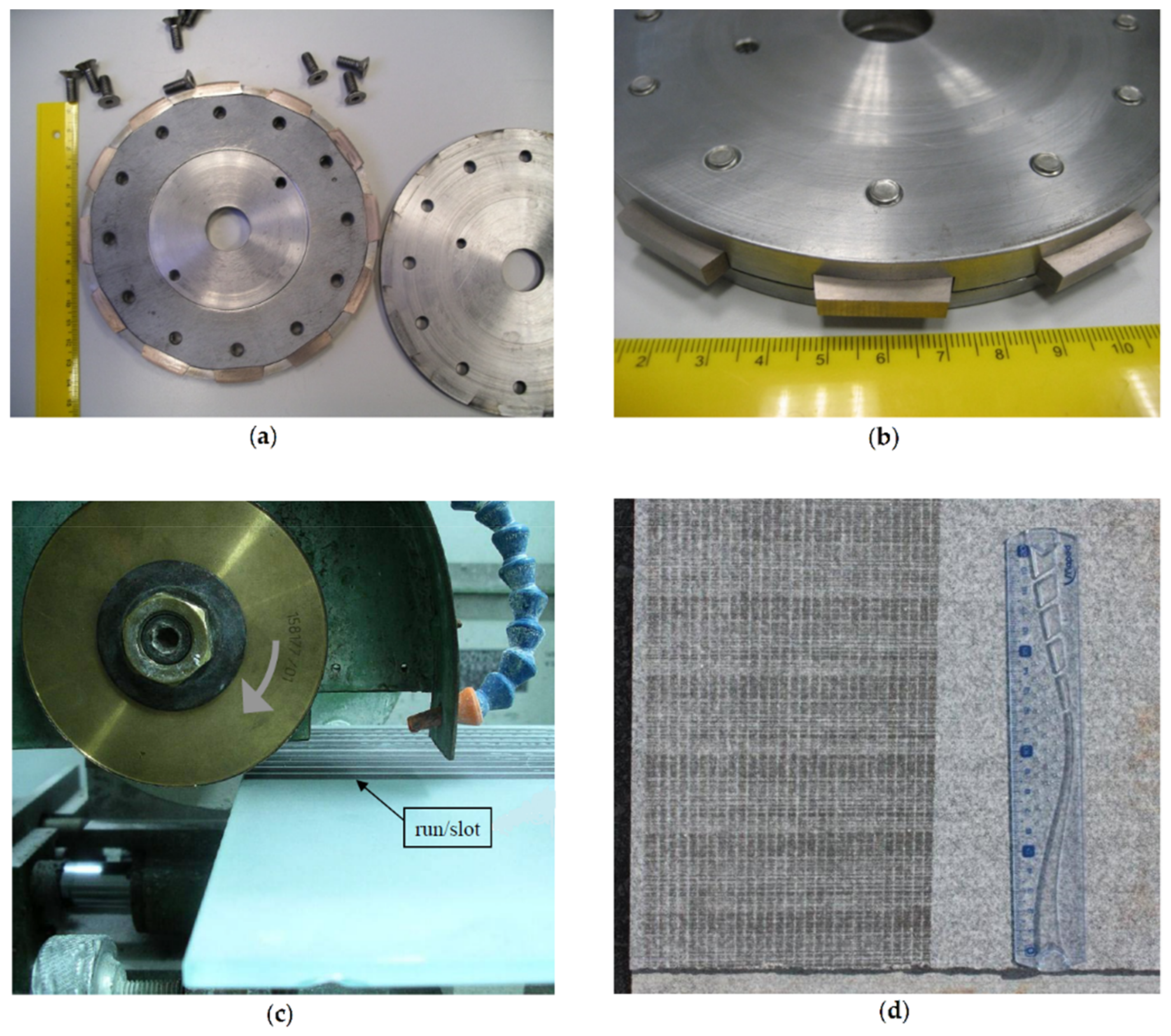
2.3. Wear Equipment and Test Procedure
- 1:
- The wheel (where the binder material is set) is clamped into the test equipment.
- 2:
- The stone is positioned on the worktable (equipped with load cells) and clamped so that vibrations do not affect the conditions for measuring the components of the forces.
- 3:
- The input parameters (working conditions) are introduced into the software according to a previously set design of experiments.
- 4:
- A pre-determined vertical force is established for the contact between the wheel (binder) and the stone material. This force is obtained by pushing the wheel, in a static condition, against the stone plate and monitoring the force till the pre-determined value is established. The output force obtained once the test is initiated (at dynamic regime) is always slightly different for that obtained when the wheel is positioned at this stage (static positioning). Therefore, experience is necessary to relate this aspect, in order to estimate the required output.
- 5:
- All counters are zeroed before starting a test.
- 6:
- During the test, the output parameters are shown in the software and stored according to a pre-determined acquisition frequency (around 10 Hz). These parameters are the vertical and horizontal forces and the electric energy consumption. Since, for the conditions used in this work, the forces and the energy are related, only force is used for analyzing the results.
- 7:
- Every time a new wheel with a new binder is installed, some runs are made till the system stabilizes the forces (within a given margin of error). This normally occurs after 1 or 2 runs in a continuous wheel (used to test the binders produced by free sintering), but a larger number of runs may be needed in a wheel with binder segments, since the installation of new segments in the rig normally fails to accomplish a perfectly circular shape.
- 8:
- The counters acquire data till the run is performed and the wheel moves forward at a nearly constant force.
- 9:
- To analyze the repeatability, at least 4 runs are performed for each of the working parameters defined in 3. More test runs may be needed if the total loss of weight in the binder specimens is lower than 0.5 g. This condition is critical when the wear tests are made against stones that do not cause significant weight loss in the binders (e.g., marbles).
- 10:
- The forces acquired produce a lot of data that are treated after ending all test sequences. From the output data it is possible to calculate the arithmetic mean value of the forces and the corresponding standard deviation.
- 11:
- To analyze the reproducibility, the test procedure is repeated in three separate rounds of experiments (from item 1 to 10).
- 12:
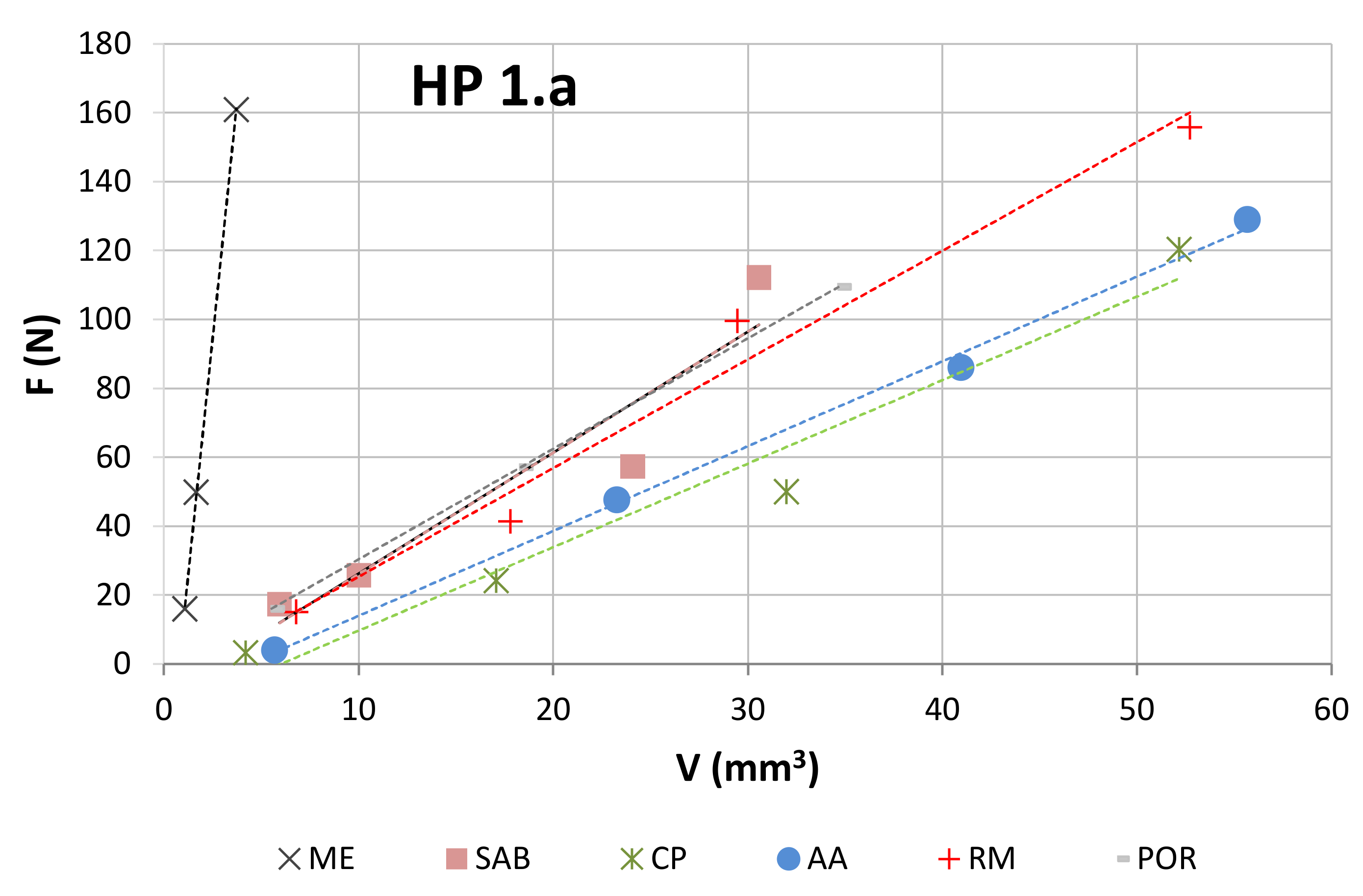
- This test sequence is repeated for each working condition (from item 1 to 11). Working conditions are defined according to the design of experiments, which may vary depending on the objective of the study. In the present study, the results of wear (total loss of volume calculated from the loss of weight) were determined for, at least, 3 different forces that are intended to simulate different contact conditions between the binder and stone material, such as those occurring when the binders (with diamond embedded) are performing real cuts.
3. Results
4. Discussion
- The normalized force to which the binder is submitted.
- The characteristics of the contact (which depend on the type of test rig).
- The difference between the mechanical properties of the materials that constitute the tribological pair (the binder and the stone material); the greater are the differences, the clearer is the applicability of Equation (5).
5. Conclusions
- The use of the present test methodology showed robustness when measuring the different wear results and representing the wear plots, and independently of the type of binder used, the test configuration (continuous or segmented), the force employed, and the material against which the binders were tested.
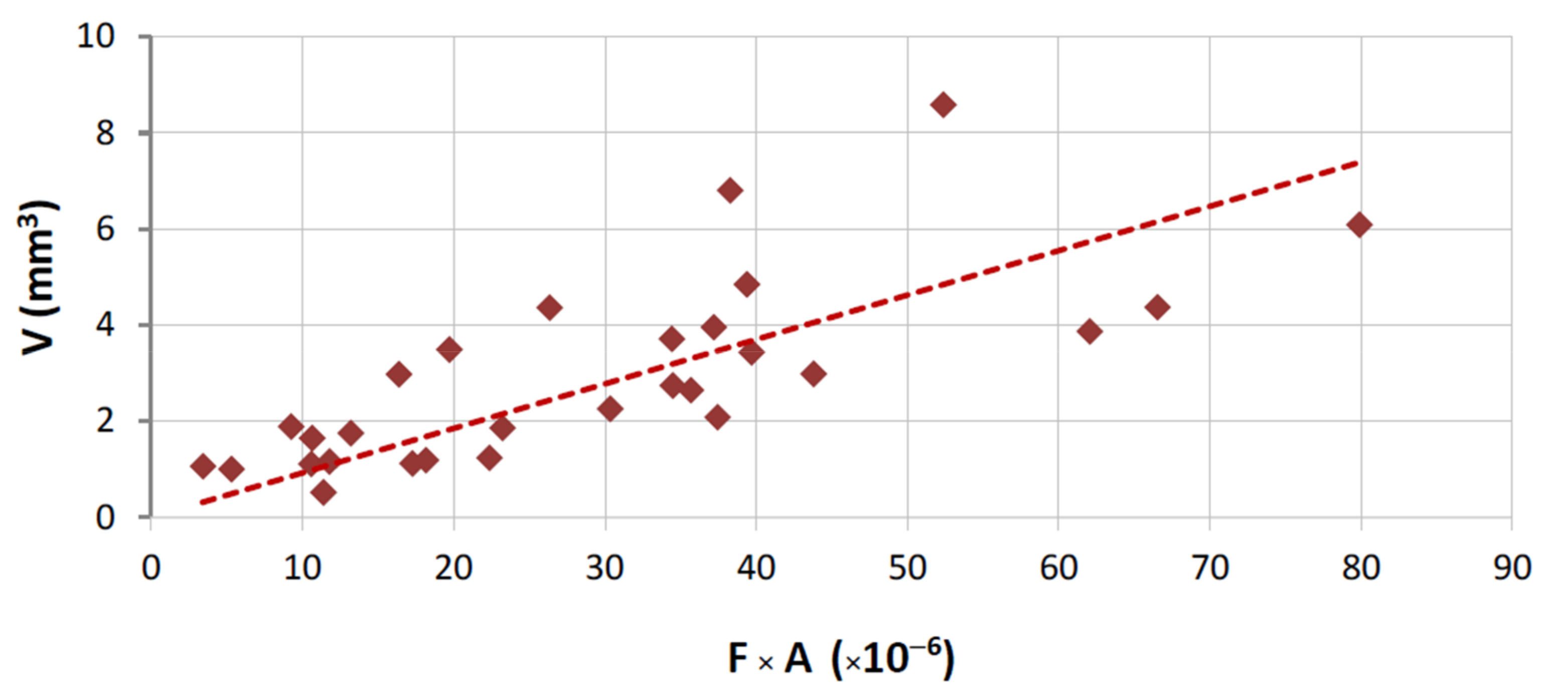
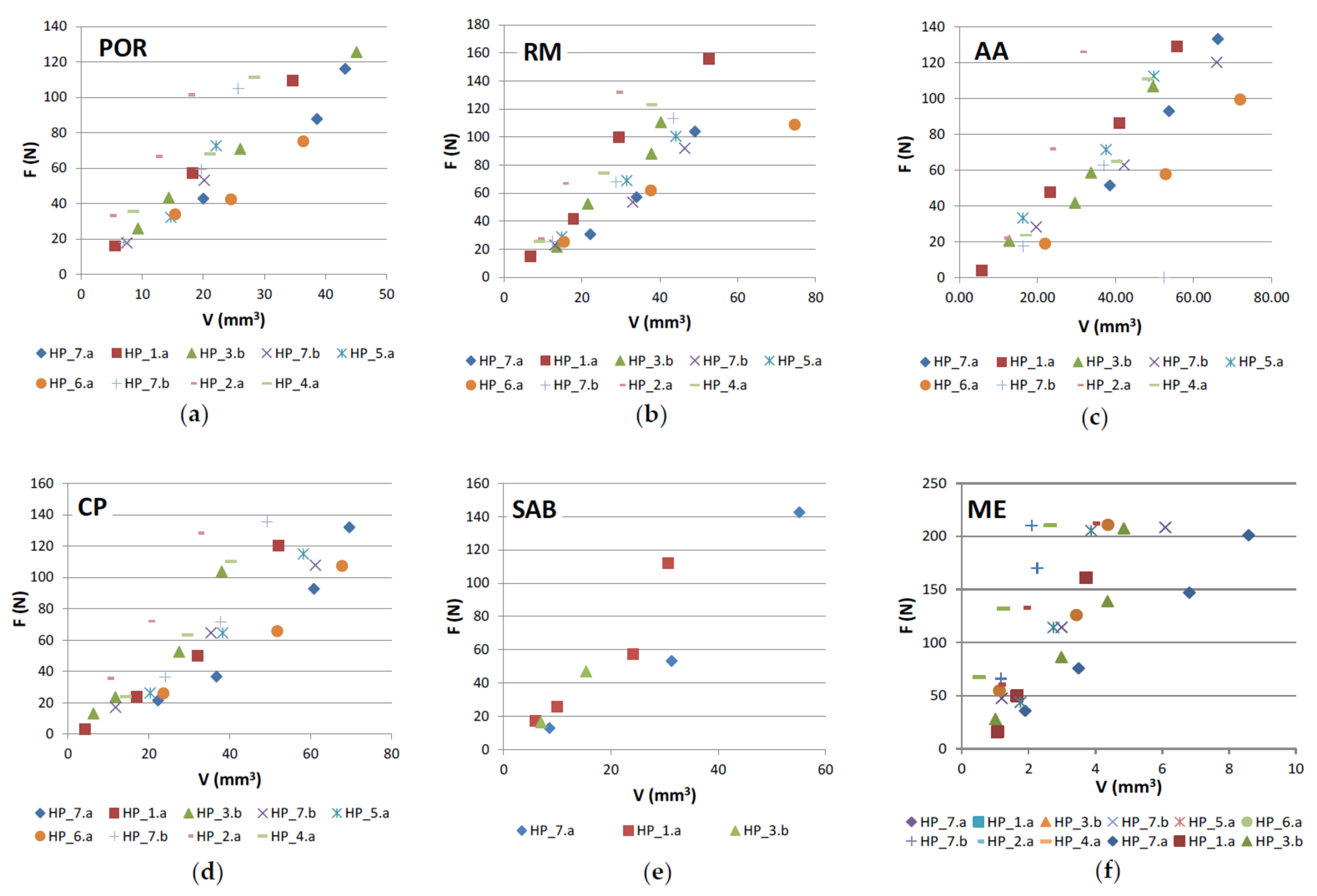
- The results of wear when testing a single binder against different stones (Figure 6) show a clear difference between the two main classes of stones under analysis (marble and granite). This suggests a difference in the contact, related to nature of the stones. In other words, when the metallic binders are tested against the granite there is a clear difference between the characteristics of the tribological pair (granite versus metallic binder). Granites have a higher influence on the wear of the binders, and hence, even if we change slightly the nature of this class of stone (suggesting a difference in the mineralogical composition), its average hardness induces a similar effect/behavior in a single type of binder. On the contrary, when using a standard plate of marble, the results suggest that the metallic binder also induces wear in the stone. By having two materials wearing at the same time, the difficulties in relating the binder properties with the wear behavior increase significantly (see Figure 12).
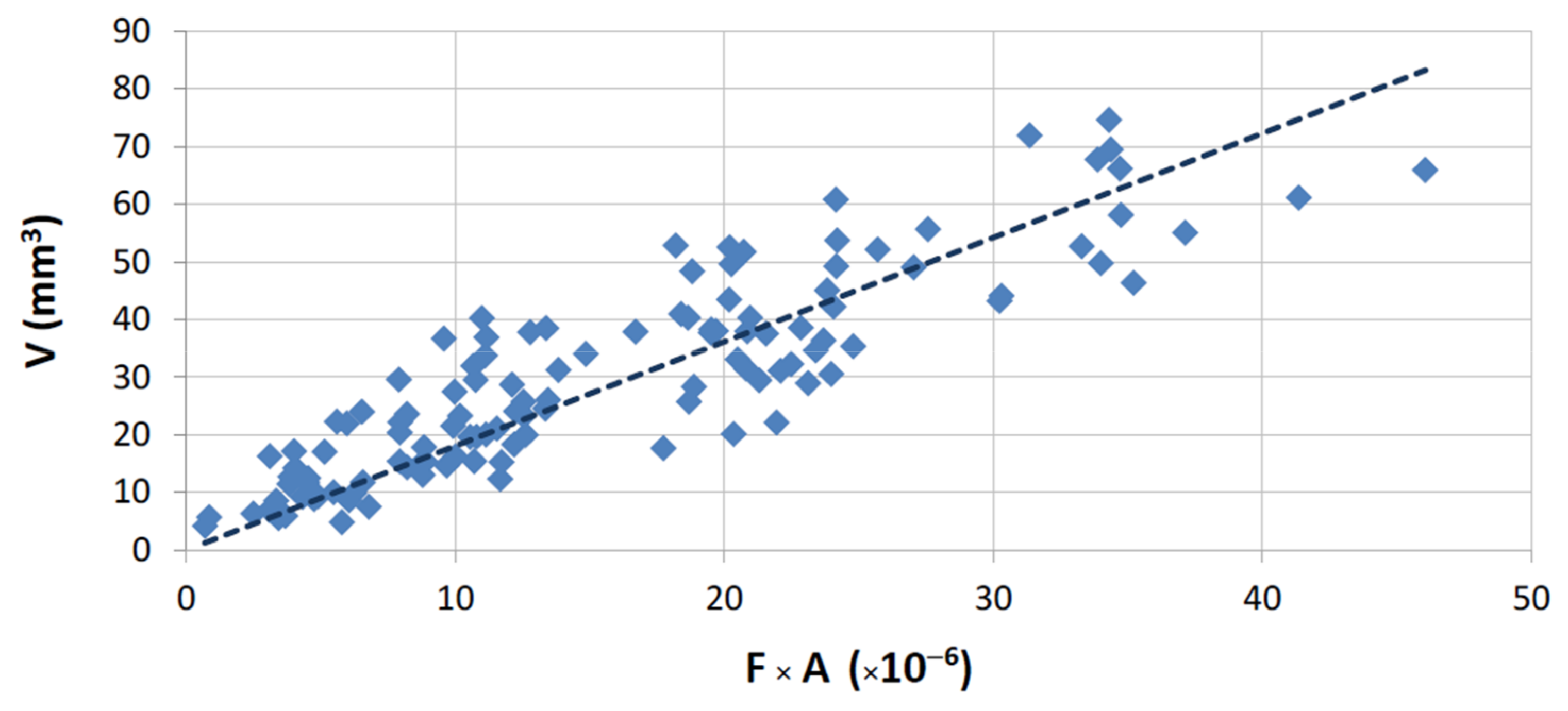
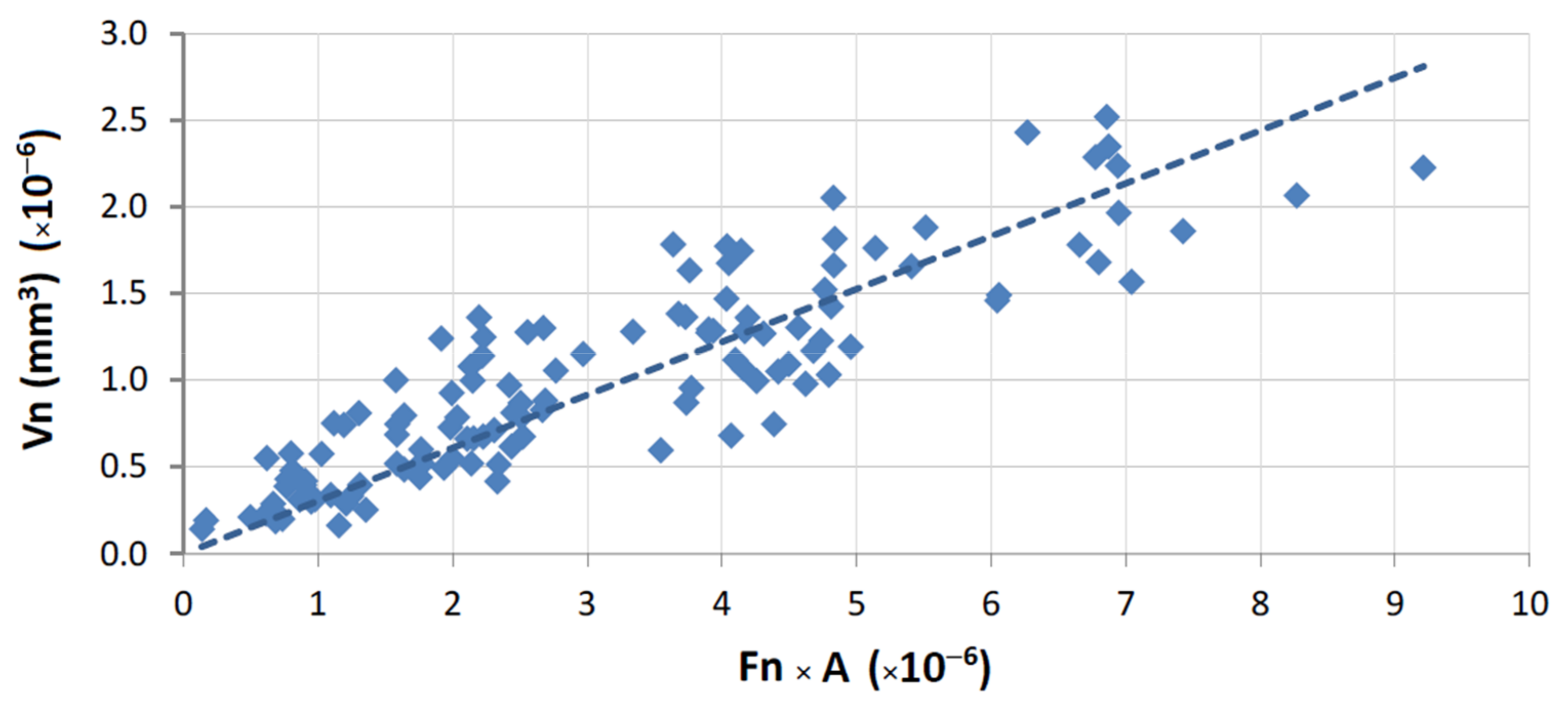
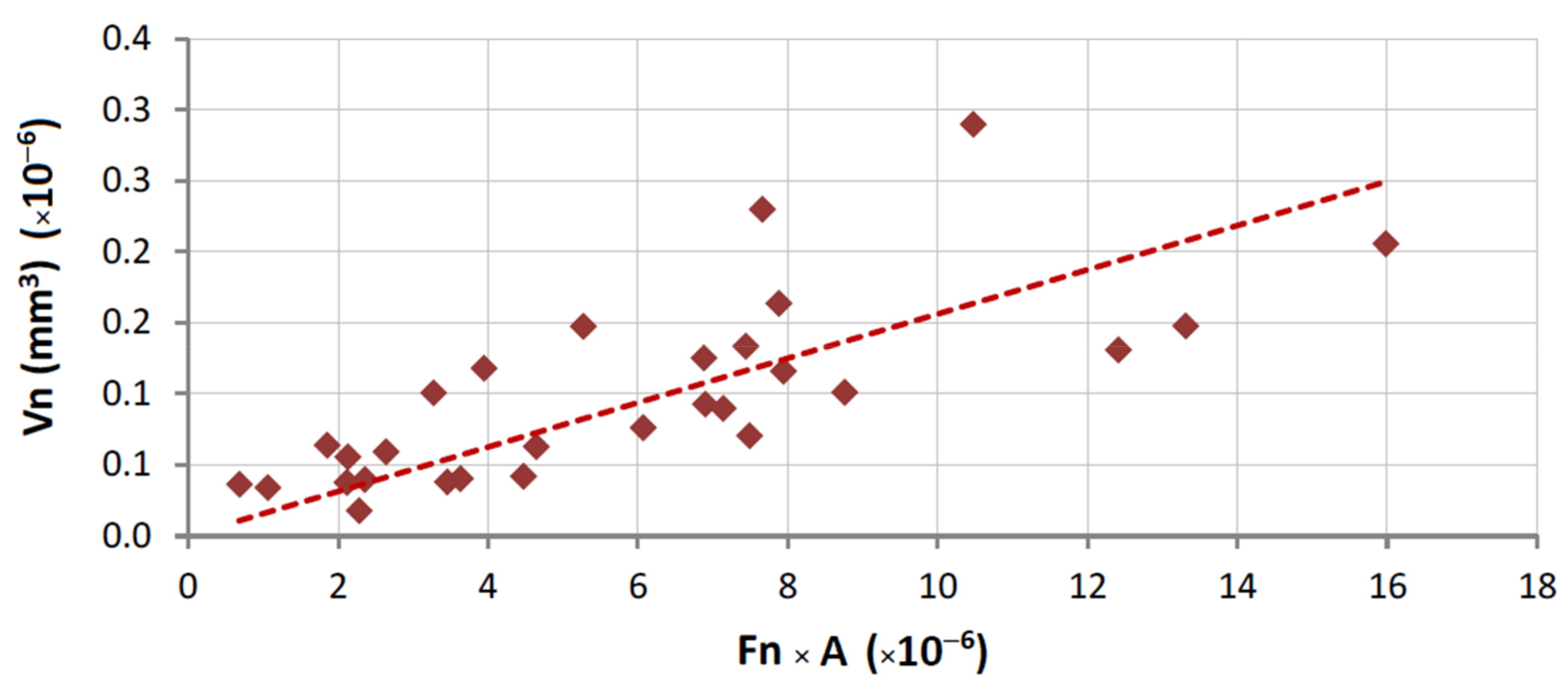
- The relation proposed in both Equation (1) (when test configuration is standard) and Equation (5) (when comparing different test configurations) gives a better fitting with the experimental data when metallic binders are tested against granite stones (R = 86.1% for segmented specimens and R = 94.1% for continuous contact). The difference between these two results may derive from the fact that the binders used in continuous wheels (free sintering) are softer than those employed in segmented configurations (hot pressing). In line with the previous item discussed, the larger the difference between the characteristics of the tribological pair, the clearer seems to be the relationship between the experimental wear data and the binder’s mechanical properties.
Author Contributions
Funding
Institutional Review Board Statement
Informed Consent Statement
Data Availability Statement
Acknowledgments
Conflicts of Interest
References
- Sung, C.-M. Brazed diamond grid: A revolutionary design for diamond saws. Diam. Relat. Mater. 1999, 8, 1540–1543. [Google Scholar] [CrossRef]
- Long, F.; He, P.; Sekulic, D.P. Research and development of powder brazing filler metals for diamond tools: A review. Metals 2018, 8, 315. [Google Scholar] [CrossRef] [Green Version]
- Konstanty, J. Theoretical analysis of stone sawing with diamonds. J. Mater. Process. Technol. 2002, 123, 146–154. [Google Scholar] [CrossRef]
- Tönshoff, H.K.; Hillmann-Apmann, H.; Asche, J. Diamond tools in stone and civil engineering industry: Cutting principles, wear and applications. Diam. Relat. Mater. 2002, 11, 736–741. [Google Scholar] [CrossRef]
- Polini, W.; Turchetta, S. Force and specific energy in stone cutting by diamond mill. Int. J. Mach. Tools Manuf. 2004, 44, 1189–1196. [Google Scholar] [CrossRef]
- Turchetta, S. Cutting force and diamond tool wear in stone machining. Int. J. Adv. Manuf. Technol. 2012, 61, 441–448. [Google Scholar] [CrossRef]
- Buyuksagis, I.S.; Rostami, J.; Yagiz, S. Development of models for estimating specific energy and specific wear rate of circular diamond saw blades based on properties of carbonate rocks. Int. J. Rock Mech. Min. Sci. 2020, 135, 104497. [Google Scholar] [CrossRef]
- Sun, Q.; Zhang, J.S.; Wang, Z.; Zhang, H.; Fang, J.Y. Segment wear characteristics of diamond frame saw when cutting different granite types. Diam. Relat. Mater. 2016, 68, 143–151. [Google Scholar] [CrossRef]
- Zhou, J.G.; Zhang, J.S.; Zhou, H.R.; Dong, P.Y.; Wang, K.D. Wear characteristics of diamond segments on multi-blade combination saw with different diameters in granite sawing. Int. J. Refract. Met. Hard Mater. 2021, 97, 105517. [Google Scholar] [CrossRef]
- Rosa, L.G.; Amaral, P.M.; Anjinho, C.A.; Fernandes, J.C. Evaluation of diamond tool behaviour for cutting stone materials. Ind. Diamond Rev. 2004, 1, 45–50. [Google Scholar]
- Rosa, L.G.; Amaral, P.M.; Fernandes, J.C. Experimental determination of young’s modulus in PM metal matrices used in diamond impregnated tools for cutting hard materials. Powder Metall. 2008, 51, 46–52. [Google Scholar] [CrossRef]
- Coelho, A. Avaliação do Desgaste em Matrizes Metálicas Usadas em Ferramentas Diamantadas e Sua Relação Com as Propriedades Mecânicas. Master’s Thesis, Instituto Superior Tecnico, Technical University of Lisbon, Lisbon, Portugal, 2008. Available online: https://fenix.tecnico.ulisboa.pt/cursos/memat/dissertacao/2353642173826 (accessed on 17 July 2020).
- Rosa, L.G.; Fernandes, J.C.; Anjinho, C.A.; Coelho, A.; Amaral, P.M. Long-term performance of stone-cutting tools. Int. J. Refract. Met. Hard Mater. 2015, 49, 276–282. [Google Scholar] [CrossRef]
- Zhao, X.; Duan, L. A review of the diamond retention capacity of metal bond matrices. Metals 2018, 8, 307. [Google Scholar] [CrossRef] [Green Version]
- Konstanty, J. Production parameters and materials selection of powder metallurgy diamond tools. Powder Metall. 2006, 49, 299–306. [Google Scholar] [CrossRef]
- Konstanty, J. Sintered diamond tools: Trends, challenges and prospects. Powder Metall. 2013, 56, 184–188. [Google Scholar] [CrossRef]
- Rosa, L.G.; Anjinho, C.A.; Amaral, P.M.; Fernandes, J.C. Mechanical properties of some metallic powder alloys and their contribution to the performance of diamond tools used for cutting granite. Metals 2019, 9, 1219. [Google Scholar] [CrossRef] [Green Version]
- Konstanty, J. Sintered diamond tools—The past, present and future. Arch. Metall. Mater. 2021, 66, 593–599. [Google Scholar] [CrossRef]
- Amaral, P.M.; Fernandes, J.C.; Rosa, L.G. Wear mechanisms in materials with granitic textures—Applicability of a lateral crack system model. Wear 2009, 266, 753–764. [Google Scholar] [CrossRef]
- Amaral, P.M.; Coelho, A.; Anjinho, C.A.; Fernandes, J.C.; Rosa, L.G. Evaluation of the relationship between diamond tool wear performance and the mechanical properties of the individual metallic binders. Mater. Sci. Forum 2010, 636–637, 1467–1474. [Google Scholar] [CrossRef]
- Fernandes, J.C.; Pinto, S.; Amaral, P.M.; Rosa, L.G. Development of a new testing method for assessing the wear behaviour of circular cutting discs. Mater. Sci. Forum 2008, 587–588, 966–970. [Google Scholar] [CrossRef]
- Amaral, P.M.; Anjinho, C.A.; Pinto, S.; Pozo, D.; Fernandes, J.C.; Rosa, L.G. Relation between the mechanical properties of binder materials and the wear behaviour caused by circular sawing. In Proceedings of the 2nd International Industrial Diamond Conference, Rome, Italy, 19–20 April 2007. [Google Scholar] [CrossRef]
- Rosa, L.G.; Coelho, A.; Amaral, P.M.; Fernandes, J.C. Test methodology to evaluate the wear performance of PM matrices used in diamond impregnated tools for cutting hard materials. In Powder Metallurgy for Automotive and High Performance Materials in Engineering Industries; Ramakrishnan, P., Ed.; New Age International Publishers: Bombay, India, 2013; pp. 186–193. [Google Scholar] [CrossRef]


| Type of Binder 1 | Elements in Composition | ρ (g/cm3) | HV (MPa) | E (GPa) | σ (MPa) | m (MPa) |
|---|---|---|---|---|---|---|
| HP_1.a | Co, Cu, Fe | 8.08 | 2533 | 195 | 832.9 | 28.61 |
| HP_2.a | Co | 8.93 | 2639 | 215 | 932.8 | 17.34 |
| HP_3.a | Co, Cu, Fe | 7.97 | 2707 | 211 | 1000.5 | 8.79 |
| HP_3.b | Co, Cu, Fe | 7.94 | 2796 | 217 | 713.7 | 22.15 |
| HP_4.a | Co, Cu, Fe | 8.29 | 2744 | 217 | 989.0 | 9.71 |
| HP_5.a | Co, Cu, Fe | 8.26 | 2683 | 186 | 625.3 | 1.12 |
| HP_6.a | Co, Cu, Fe, Sn | 8.45 | 2559 | 175 | 702.8 | 1.57 |
| HP_7.a | Co, Cu, Fe | 8.44 | 2919 | 181 | 783.9 | 2.30 |
| HP_7.b | Co, Cu, Fe | 8.37 | 2840 | 175 | 468.0 | 0.61 |
| FS_8.a | Cu, Sn, Co | 8.01 | 2247 | 130 | 270.8 | 0.30 |
| FS_9.a | Co, Cu, Sn | 8.10 | 1682 | 110 | 278.9 | 1.65 |
| FS_10.a | Co, Cu, Sn | 8.20 | 1325 | 125 | 298.1 | 0.67 |
| FS_11.a | Cu, Sn | 8.30 | 1500 | 102 | 191.6 | 0.24 |
| FS_12.a | Co, Cu, Fe | 7.38 | 2674 | 215 | 422.0 | 0.46 |
| FS_13.a | Fe, Cu, Co | 7.40 | 2349 | 220 | 977.5 | 3.38 |
| “Porriño” (POR) | South African Black (SAB) | ||
| Biotitic granite, with large grains and with some irregular fractured megacrystals of dark rose K-feldspar | Gabbro, with a homogeneous distribution of very dark pyroxene and grey feldspar grains (in the boundary of the former) | ||
| Quartz (35%) K-feldspar (40%) Plagioclase (13%) Biotite (11%) Other (1%) |  | Plagioclase (55%) Pyroxene (45%) | 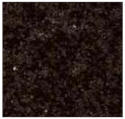 |
| “Azul Alpalhão” (AA) | “Rosa Monção” (RM) | ||
| Two mica granite (mostly biotitic), with a well distributed fraction of fine grains (light grey) | Biotitic granite, with large grains and with some megacrystals of light rose K-feldspar | ||
| Quartz 30% K-feldspar (40%) Plagioclase (12%) Biotite (10%) Muscovite (7%) Other (1%) | 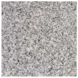 | Quartz (40%) K-feldspar (40%) Plagioclase (10%) Biotite (10%) | 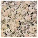 |
| “Cinza Pinhel” (CP) | “Mármore Estremoz” (ME) | ||
| Two mica granite (mostly biotitic), with medium to coarse grains and presenting a few megacrystals of feldspar | Calcitic marble, showing a fine to medium grained granoblastic texture | ||
| Quartz (35%) K-feldspar (40%) Plagioclase (12%) Biotite (10%) Muscovite (2%) Other (1%) | 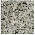 | Calcite (99%) Other (1%) | 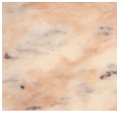 |
| Type of Wheel | Nominal Diameter, D (mm) | Nominal Partition (r = total Length of Binder Material in the Wheel/Perimeter) | Nominal Width of Contact, w (mm) | Distance of Each Run, L (mm) 1 | Peripheral Speed, p (m/s) |
|---|---|---|---|---|---|
| Segmented | 156 | 0.55 | 5 | 190 | 19.7 |
| Continuous | 125 | 1.00 | 10 | 190 | 23.0 |
| Type of Stone | V (g) | V (mm3) | cv | F (N) | cv |
|---|---|---|---|---|---|
| POR | 0.04 | 5.53 ± 0.23 | 4.2% | 16.00 ± 0.88 | 5.5% |
| 0.15 | 18.32 ± 0.95 | 5.2% | 57.06 ± 2.57 | 4.5% | |
| 0.28 | 34.65 ± 1.25 | 3.6% | 109.42 ± 5.03 | 4.6% | |
| RM | 0.05 | 6.81 ± 0.31 | 4.5% | 15.13 ± 0.64 | 4.2% |
| 0.14 | 17.82 ± 0.86 | 4.8% | 41.31 ± 2.27 | 5.5% | |
| 0.24 | 29.46 ± 1.71 | 5.8% | 99.62 ± 6.08 | 6.1% | |
| 0.43 | 52.72 ± 3.64 | 6.9% | 155.72 ± 9.03 | 5.8% | |
| AA | 0.05 | 5.69 ± 0.39 | 6.8% | 3.96 ± 0.15 | 3.9% |
| 0.19 | 23.27 ± 1.51 | 6.5% | 47.59 ± 1.81 | 3.8% | |
| 0.33 | 40.97 ± 1.84 | 4.5% | 86.03 ± 4.65 | 5.4% | |
| 0.45 | 55.69 ± 1.73 | 3.1% | 129.00 ± 2.97 | 2.3% | |
| CP | 0.03 | 4.21 ± 0.22 | 5.2% | 3.25 ± 0.19 | 5.7% |
| 0.14 | 17.08 ± 1.38 | 8.1% | 24.04 ± 1.39 | 5.8% | |
| 0.26 | 31.99 ± 2.82 | 8.8% | 49.90 ± 2.54 | 5.1% | |
| 0.42 | 52.17 ± 3.91 | 7.5% | 120.28 ± 3.13 | 2.6% | |
| SAB | 0.05 | 5.94 ± 0.49 | 8.2% | 17.23 ± 0.72 | 4.2% |
| 0.08 | 10.02 ± 0.79 | 7.9% | 25.64 ± 0.92 | 3.6% | |
| 0.19 | 24.09 ± 2.12 | 8.8% | 57.35 ± 2.18 | 3.8% | |
| 0.25 | 30.57 ± 2.11 | 6.9% | 112.13 ± 5.49 | 4.9% | |
| ME | 0.01 | 1.07 ± 0.05 | 4.5% | 15.96 ± 0.78 | 4.9% |
| 0.01 | 1.65 ± 0.10 | 6.3% | 49.76 ± 2.94 | 5.9% | |
| 0.03 | 3.71 ± 0.18 | 4.8% | 160.94 ± 8.21 | 5.1% |
Publisher’s Note: MDPI stays neutral with regard to jurisdictional claims in published maps and institutional affiliations. |
© 2021 by the authors. Licensee MDPI, Basel, Switzerland. This article is an open access article distributed under the terms and conditions of the Creative Commons Attribution (CC BY) license (https://creativecommons.org/licenses/by/4.0/).
Share and Cite
Ternero, F.; Amaral, P.M.; Fernandes, J.C.; Rosa, L.G. Evaluation of Wear Behaviour in Metallic Binders Employed in Diamond Tools for Cutting Stone. Materials 2021, 14, 3988. https://doi.org/10.3390/ma14143988
Ternero F, Amaral PM, Fernandes JC, Rosa LG. Evaluation of Wear Behaviour in Metallic Binders Employed in Diamond Tools for Cutting Stone. Materials. 2021; 14(14):3988. https://doi.org/10.3390/ma14143988
Chicago/Turabian StyleTernero, Fátima, Pedro M. Amaral, Jorge Cruz Fernandes, and Luís Guerra Rosa. 2021. "Evaluation of Wear Behaviour in Metallic Binders Employed in Diamond Tools for Cutting Stone" Materials 14, no. 14: 3988. https://doi.org/10.3390/ma14143988
APA StyleTernero, F., Amaral, P. M., Fernandes, J. C., & Rosa, L. G. (2021). Evaluation of Wear Behaviour in Metallic Binders Employed in Diamond Tools for Cutting Stone. Materials, 14(14), 3988. https://doi.org/10.3390/ma14143988