1. Introduction
Most of the publications taking thermal phenomena in brake discs into consideration focus on the destructive effects of friction rings on the disc material. It has been shown that changes in the volume of the material due to its thermal expansion in the areas of overheating lead to compressive stresses during heating and tensile stresses during cooling. Multiple repetitions of this cycle lead to a gradual increase in stresses up to the limit of the tensile strength of the disc material. This phenomenon, described in many publications [
1,
2,
3,
4,
5,
6,
7,
8], causes cracks that grow with each successive braking of the vehicle.
In [
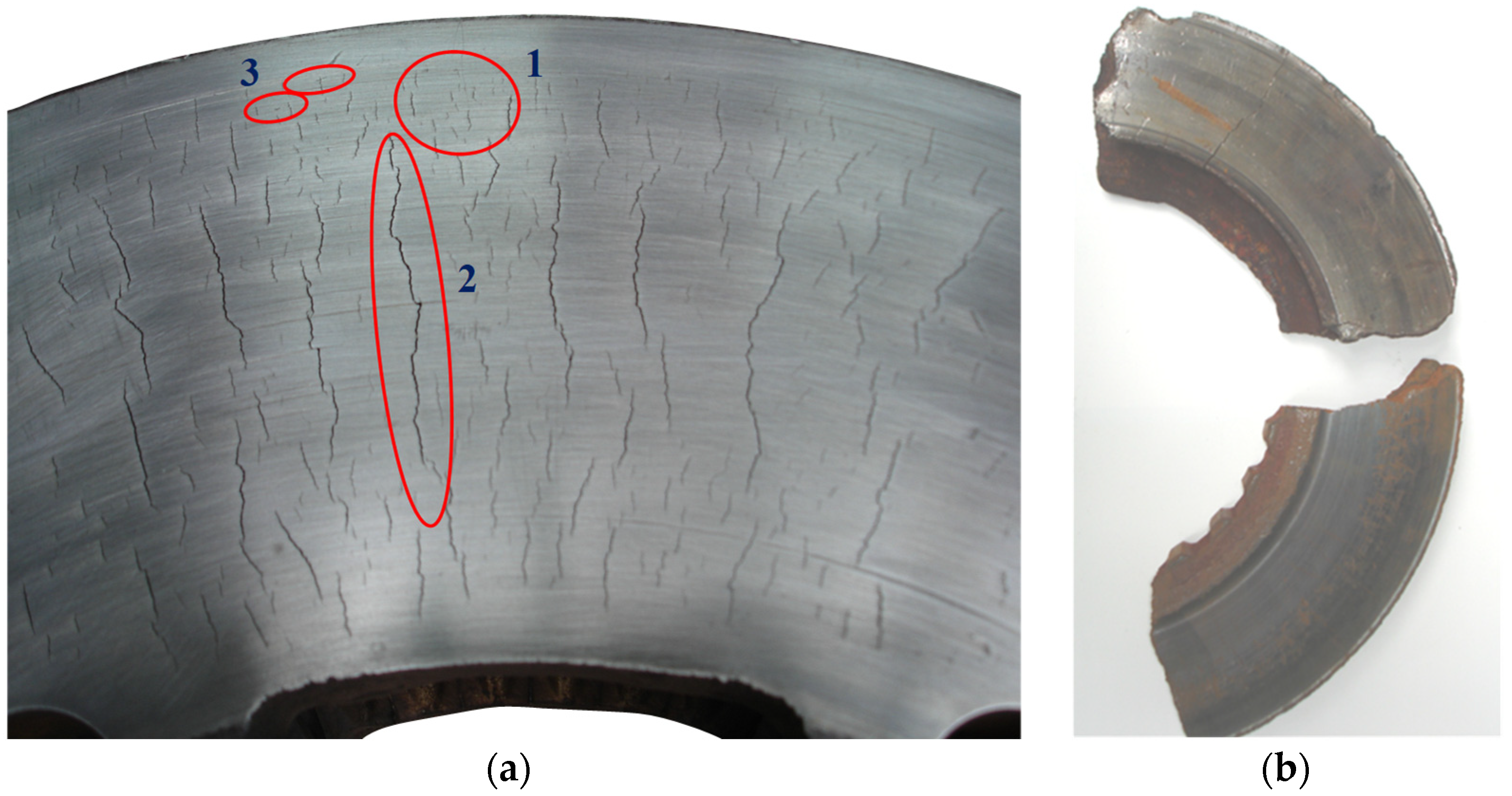
9], three basic surface cracks were distinguished, caused by thermal and mechanical stresses in the friction ring of the disc. These were microcracks, radial cracks and circumferential cracks, which the authors of this article also observed during their own observations and research. However, circumferential cracks are rare and circumferential scratches are more common. Circumferential cracks are caused by the penetration of hard debris between the cladding and the disc, such as sand grains from a track or road. Scratches are not related to thermo-mechanical phenomena occurring during braking. The number of circumferential cracks in long-term operation changes due to the phenomenon of abrasive friction. Some of the scratches are ground in subsequent braking and new ones appear. A view of a brake disc with various failures and an example of the disc fragments after its fracture are shown in
Figure 1.
Radial cracks usually begin inside the material and on the rim of the recorded macroscopic hot spots [
10]. In addition, radial cracks (
Figure 2a) grow from a single fracture or by the joining of successive fractures along the same radius (the most frequent phenomenon), which has been confirmed by researchers [
11,
12].
Moreover, [
10] showed that, as a result of the solid-solid phase transformations and mechanical stress, cracks can also occur parallel to the friction surface in the depth of the material. This is a phenomenon that contributes to the spalling of a fragment of the brake disc. The abovementioned study also confirmed that the areas where no local or macroscopic overheating occurred are free from mechanical damage; then, there are no cracks on the friction surface (
Figure 2b).
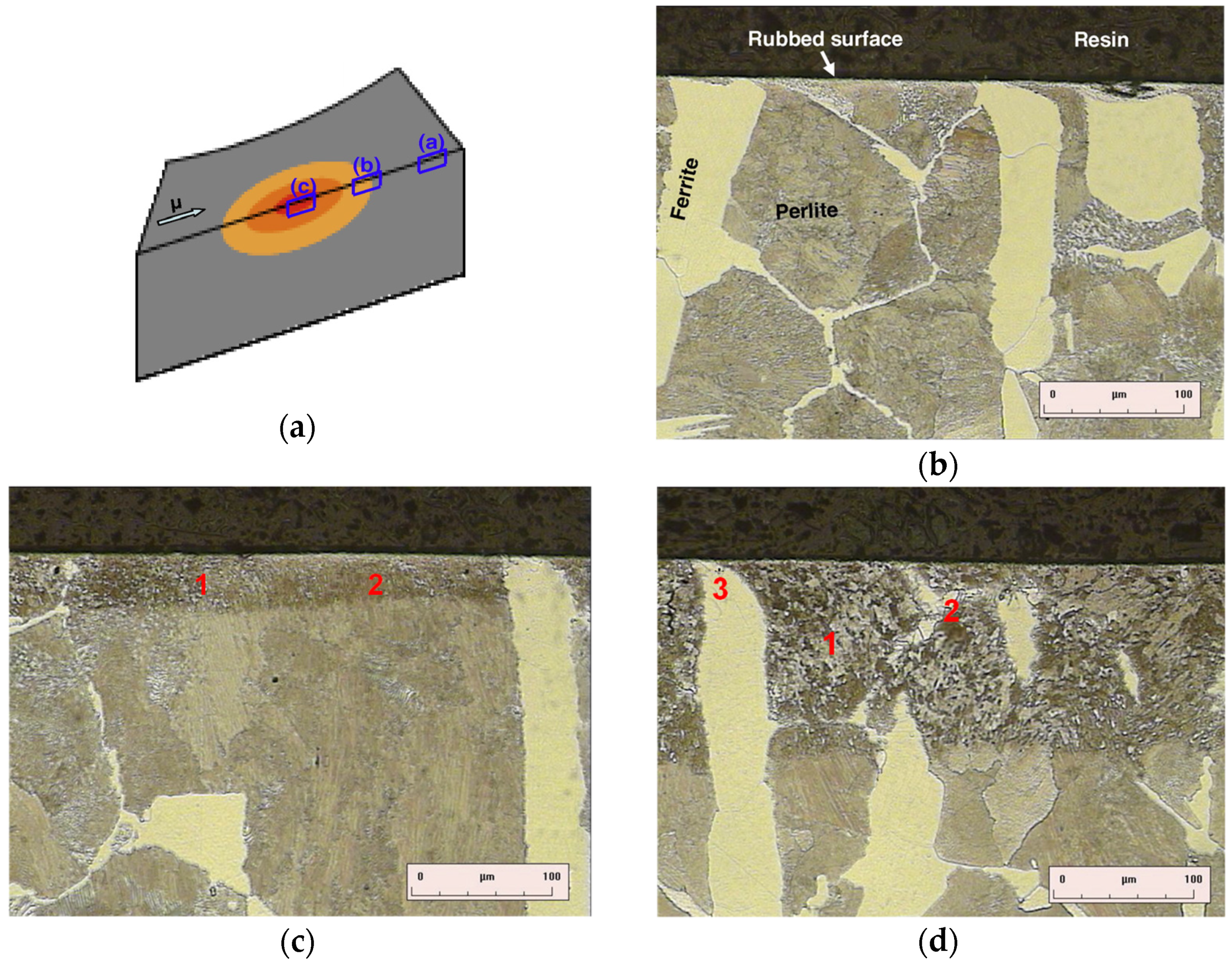
Observations of phase transformations in the material structure indicated that local overheating causes changes in the structure of the disc to a depth of about 120 µm [
13]. Tests on a disc made of carbon steel C48 for surface hardening proved the presence of only two components of the phases, i.e., the α
f-ferrite phase containing less than 0.02% carbon and eutectic perlite containing about 0.8% carbon. Both phases, due to overheating, transform into the γ-austenite phase. The distribution of austenite precipitates depends on the cross-section of the material due to different austenitizing temperatures of the primary phases from 890 to 720 °C. Then, as a result of cooling, the austenitized areas proceed in a reverse transformation, where ferrite appears in the form of a finer grain and the perlite occurs in the form of a mixture of bainite and fine pearlite, as shown in
Figure 3.
In order to avoid the phenomenon of surface cracks on brake discs, many research centers have conduct research on new materials for brake discs described in the articles [
14,
15,
16,
17,
18,
19]. These works are preceded by various numerical analyses in terms of stress concentrations, which were also presented in [
20,
21,
22,
23,
24,
25,
26,
27,
28].
Knowledge of the fracture mechanisms and the geometrical parameters of the fractures is crucial from the point of view of the operation of vehicles equipped with disc brakes. Thermal cracks in the friction surface usually cause disc replacement with new ones, much earlier than it would be necessary to wear the material. As long as the cracks are shallow, they can be removed by turning the disc. Nevertheless, if their depth is greater than the manufacturer’s recommended maximum thickness loss of the friction ring, this operation will not make sense, because the regenerated disc will not be allowed for further use and will need to be replaced with a new one. This issue has not been analyzed so far, which created an unfilled gap in the practical application of previously conducted research around the world. In this article, a simple tool that will allow, based on simple measurements, to determine whether a brake disc can be regenerated and still be in service was created. Thus, this tool will allow to reduce the number of unnecessary replacements of this component and the operating costs of the vehicle.
The main goal of the research is to identify the surface cracks of rail vehicle brake discs and to develop a method for estimating the depth of the crack on the basis of its length. Determining both the crack length, as well as depth, is essential from the point of view of the safety of vehicles with disc brakes. The research used mainly non-destructive methods, and the developed models of the crack depth will allow better and faster diagnostics of brake disc cracks in the future.
2. Methodology of Testing Surface Cracks
Research in the field of identifying cracks on brake disc surfaces was carried out in several stages. First, bench tests were carried out on railway brake discs. This research was conducted using the same methodology as in [
29,
30]. The research was carried out in at Łukasiewicz Research Network IPS TABOR in Poznan, Poland. During these tests, two brake discs, T1 (Nodular Cast Iron) and T2 (Grey Cast Iron), with dimensions of 610 mm × 110 mm (diameter × disc thickness) were used. The main difference between the discs was the chemical composition. The T2 disc had a higher copper content than the T1 disc. The discs were prepared for testing in accordance with [
31,
32]. The program for the stand tests is presented in
Table 1. The tests were carried out taking into account the pad test procedure contained in [
33].
In the second part of research, penetration tests were performed to observe the actual number of surface cracks and their length. The research was based on the following publications [
34,
35]. In the third part of the research, tests were carried out to assess the depth of surface cracks.
Due to the nature of surface cracks and the shape of the brake disc, it is currently difficult to investigate the depth of this defect using known non-destructive methods (such as ultrasonic, magnetic or other methods). In such types of cracks, it is best to use crack depth gauges with a potential probe, i.e., the RMG 4015 instrument (Karl Deutsch GmbH, Wuppertal, Germany). Determining the depth of cracks with a potential probe according to [
36] is based on measuring the electrical resistance between two points on the surface of the metallic test object. When there is a crack between these two points, the electrical resistance is greater than for a non-cracked surface. With alternating current, the electric field lines are displaced outwards from the material in the area below the surface. With increasing frequency, the current density also increases as does the penetration depth, δ
p, after which the current density decreases by 63%, and is shown by the relationship [
37]:
where:
σe—specific electrical conductivity, S/m;
μ—relative magnetic permeability;
μo—magnetic permeability constant, H/m;
fp—Alternating current frequency Hz.
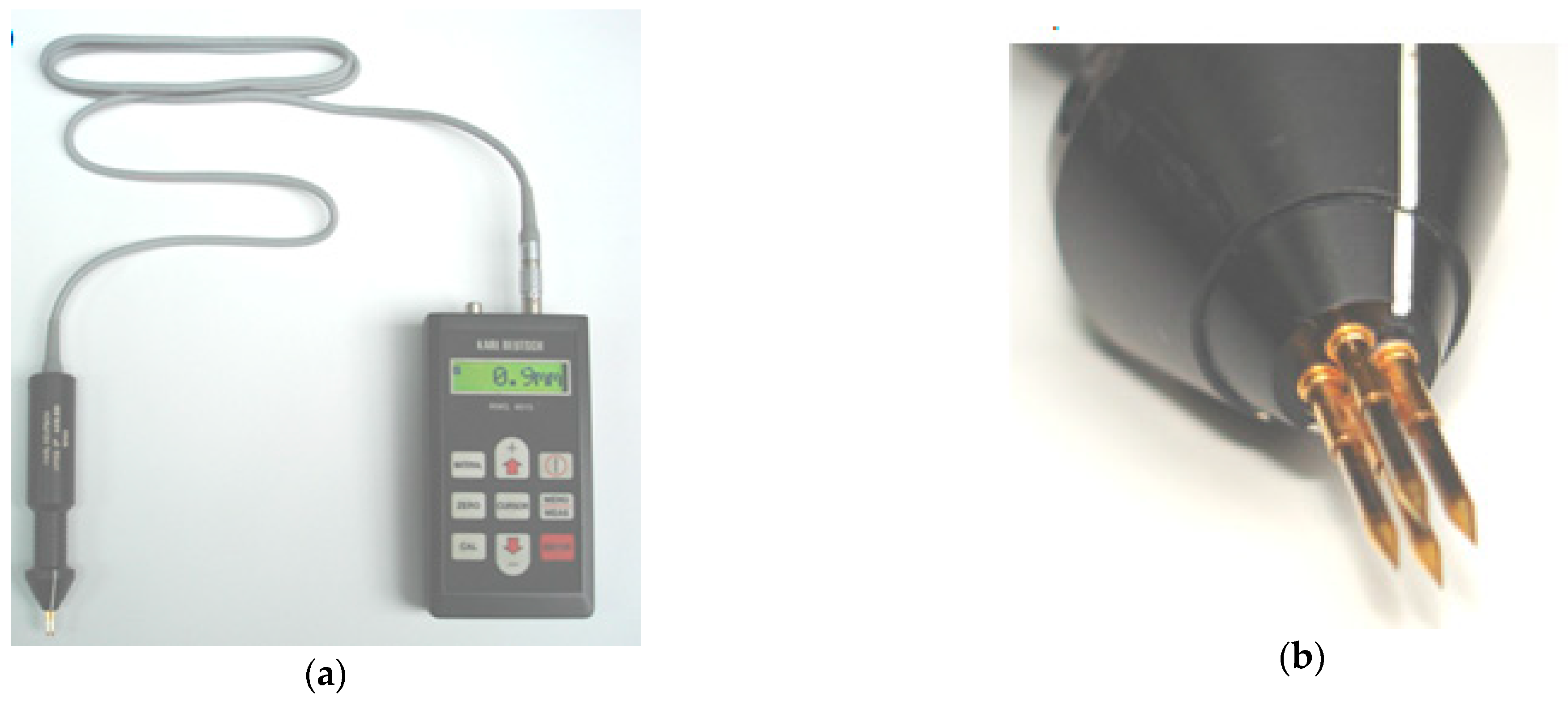
Figure 4 shows a surface crack depth Karl Deutsch measuring instrument (Karl Deutsch GmbH, Wuppertal, Germany), with a perpendicular cracking head.
The probe shown in
Figure 4b is four-pole in a square configuration and consists of two current and two measurement poles. The tips of the probe in relation to the pilot sleeves are elastically mounted and made of hardened steel, which ensures good electrical contact with the test object. In addition, the measuring probes are also available in a four-pole system with poles arranged in series to measure cracks occurring at an angle to the surface (plane) of the object.
3. Penetrant Test Results
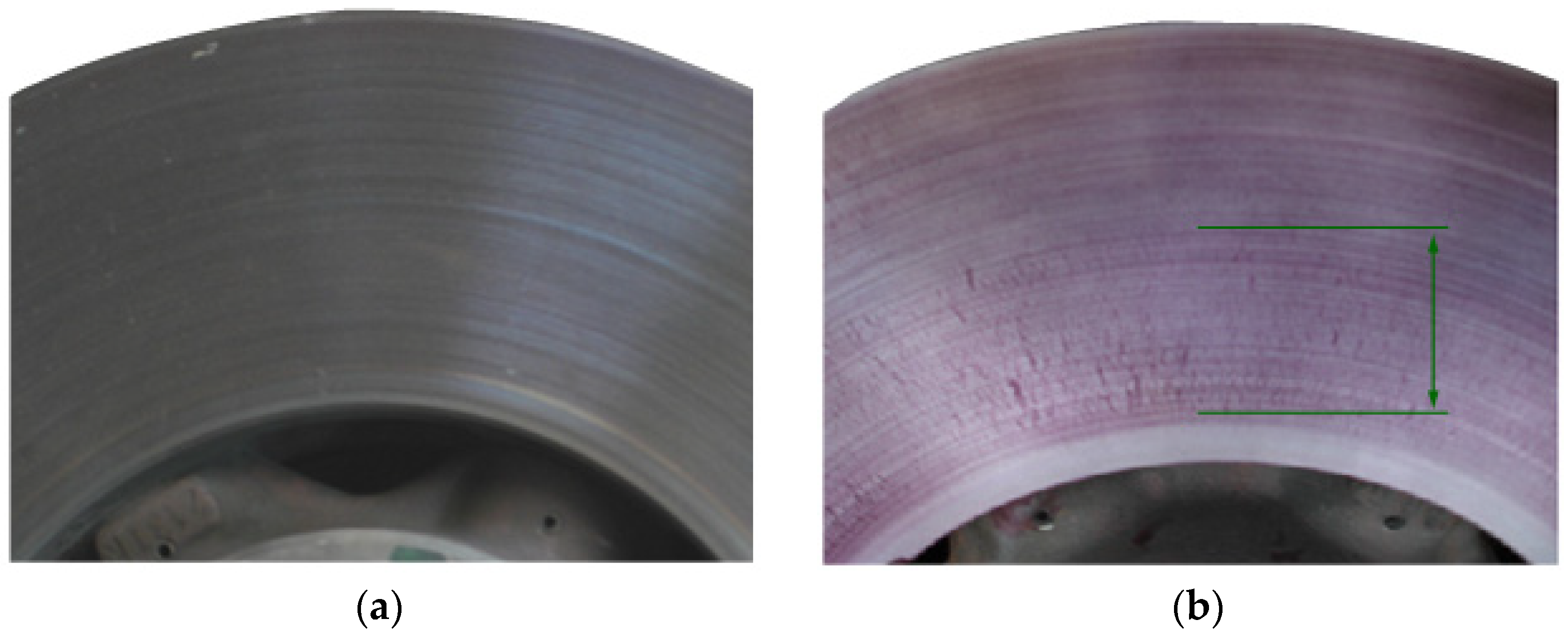
Bench tests of brake discs after 309 brakings, combined with non-destructive (penetration) tests, showed that surface cracks appeared on new discs after several hundred braking operations. The first microcracks in the area of the inner diameter of the disc are visible only with the use of penetration tests, as shown in
Figure 5. Further braking on the test bench disclosed the first cracks (3 cracks) with a length not exceeding 7 mm, visible to the eye, and are shown in
Figure 5 and
Figure 6.
The brake discs were tested according to the schedule presented in
Table 1. The appearance of the first surface cracks on the T2 disc was related to the grade of cast iron and the composition of the chemical elements (additives). In the case of the disc T2, gray cast iron was used, while disc 1 was made of nodular cast iron. The chemical compositions as a percentage of additives are presented in
Table 2. The discs were not subjected to thermo-chemical treatment.
The appearance of the first surface cracks does not disqualify the brake disc from further use. Only when the cracks grow to a dangerous size across the entire width of the ring it is necessary to replace the disc or regenerate of the friction surface [
38].
4. Examination of the Depth of Surface Cracks
Surface cracks occurring in brake discs during repeated braking as a result of exceeding the crack length in accordance with the technical and operational documentation of rail vehicles [
39,
40] force the vehicle owner to regenerate the friction surface or even replace the disc. Although the abrasive wear measured on the thickness of the disc is not exceeded, due to thickness of the brake disc being about 20–25 mm, it is important to determine the depth of cracks in order to check if a crack is not through the entire disc. In each case, it was found that, in rail vehicles, brake discs are dismounted due to too many individual surface cracks, although there was no evidence of a linear wear increase in the thickness of the disc as a result of friction between the pads and the brake disc. In some cases, the friction surfaces of the discs are machined on a lathe. However, if surface cracks are still visible after turning, the disc should be replaced with a new one. The portable device used by the authors is the RMG 4015 device made by Karl Deutsch (Wuppertal, Germany). In the research presented in this article, the indication of crack depth measured with the RMG 4015 device was checked, as well as the actual depth of the crack. In addition, the ultrasonic method was used because it allows the location of cracks and the assessment of the condition of machines and individual joints [
41,
42]. In addition, an ultrasonic magneto-particle test (Karl Deutsch GmbH, Wuppertal, Germany) was performed.
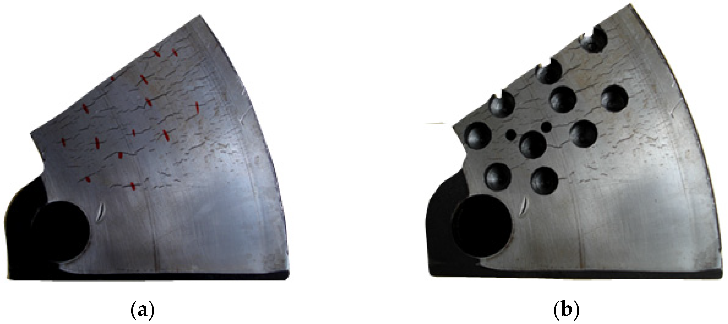
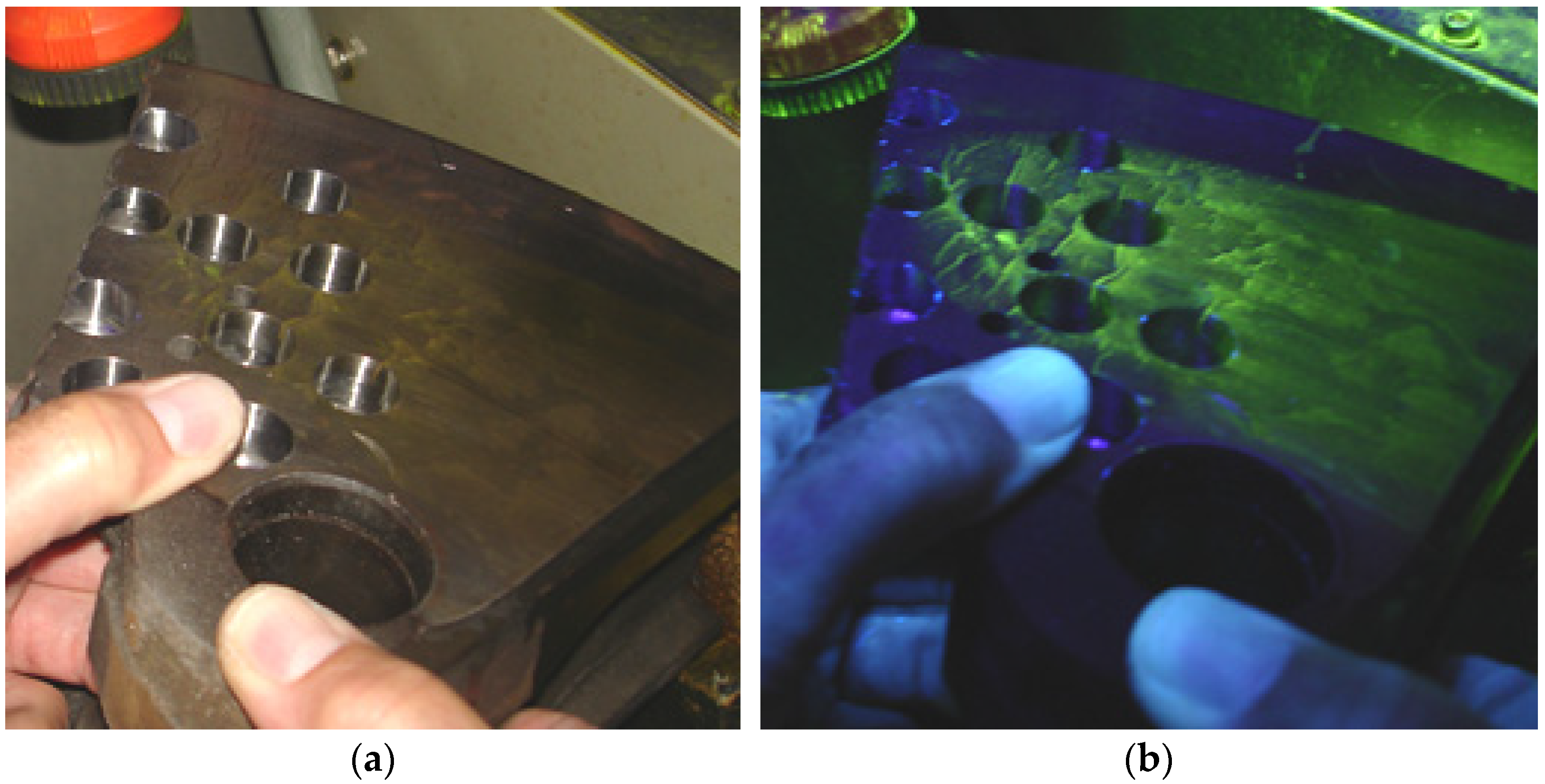
For the friction ring segment of the 610 mm × 110 mm-type brake disc, holes were made in several microcracks in the middle of their lengths, which is shown in
Figure 7. Thanks to this, it was possible to observe the actual crack depth and the crack shape. The cracks shown in
Figure 7a were measured prior to making the blind holes.
Additionally, in order to better observe the shape of the crack cross-section and its depth, magneto-particle tests were performed and the result are shown in
Figure 8.
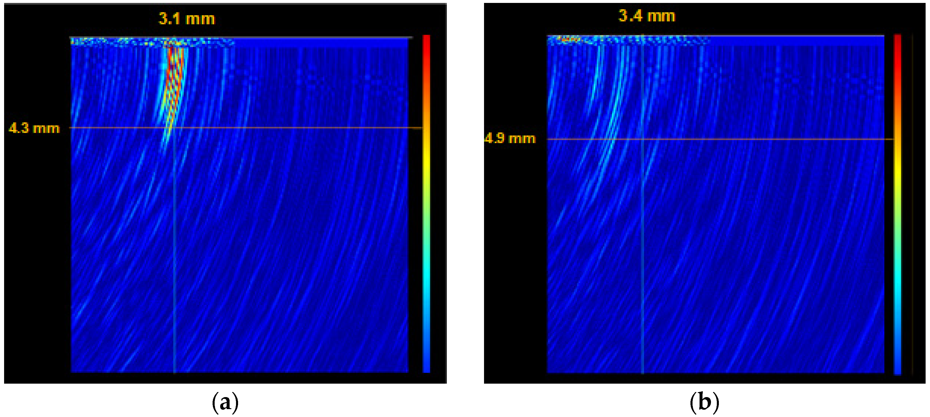
Then, the cracks indicated in
Figure 7a were examined using the ultrasonic method with a GEKON (Karl Deutsch GmbH, Wuppertal, Germany) ultrasonic flaw detector to assess the depth of the crack.
Figure 9 shows two selected visualizations of the crack depth.
On 14 marked microcracks on the brake disc section (
Figure 7a), and the crack depths measured with the RMG 4015 device, as well as those verified with the GEKON ultrasonic flaw detector, the relative percentage error of the measurement with the RMG 4015 device was in the range of 9–16%. Taking this into account, it was concluded that the RMG 4015 device can be used in measuring the depth of cracks at the surface of brake discs of rail vehicles.
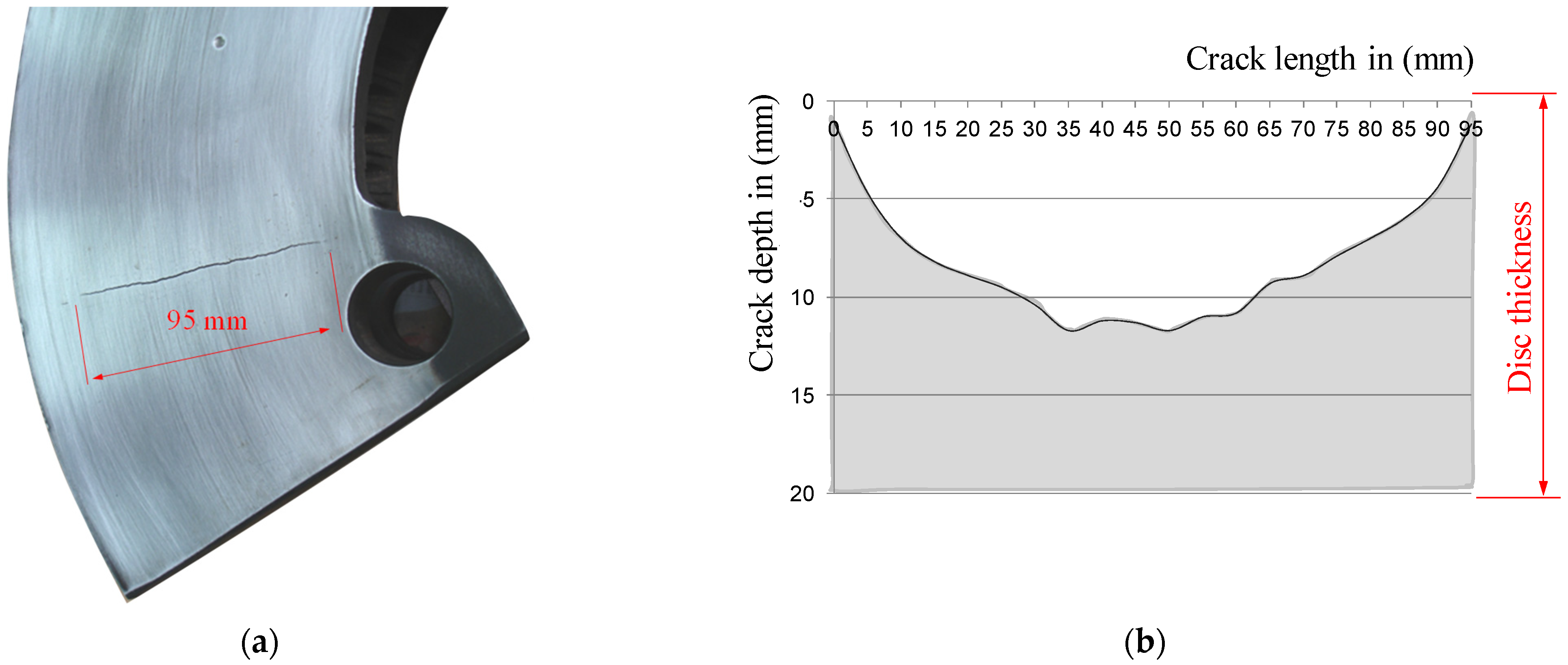
Then, the depth of surface cracks was measured on subsequent parts of the brake discs, every 5 mm of the crack length.
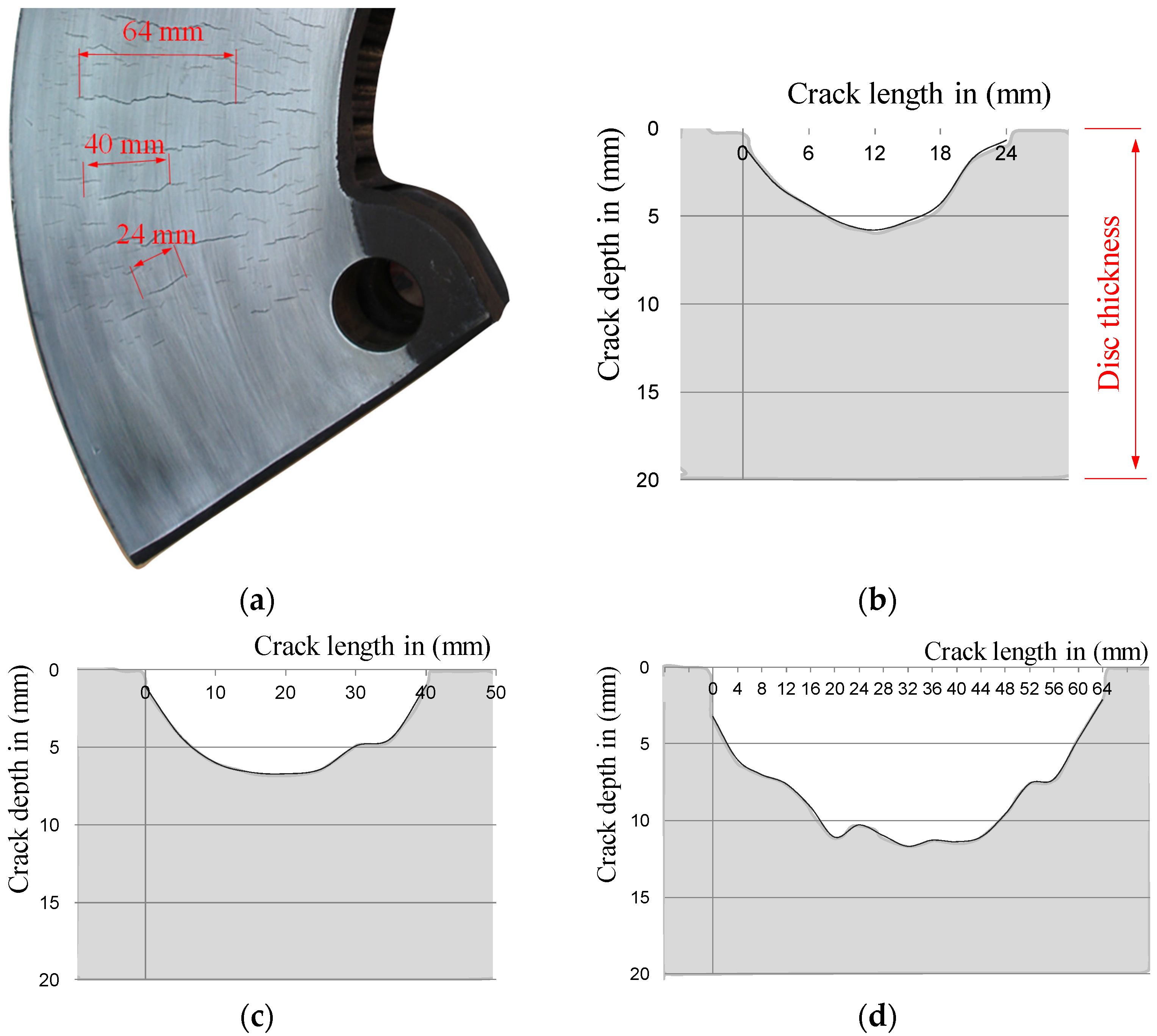
Figure 10 and
Figure 11 show the results of testing the depths of selected surface cracks using the potential probe of the RMG 4015 instrument, along with the view of these cracks.
For further research, of which the main goal was to determine the depth of surface cracks, three brake discs were selected randomly from passenger carriages running in the planned national timetable. Due to numerous microcracks, the length of which exceeded the requirements set out in the regulations [
39,
40] regarding the maintenance of these wagons, the discs were dismantled after a period of about five years. The number of microcracks on one side of the disc ranged from 40 to 60, depending on the tested disc. Then the surface cracks were grouped into classes of their length intervals, every 5 mm, in order to determine the ratio of the microcrack length to its depth.
Figure 12a,c shows histograms of the number of thermal cracks on one side of the brake disc. In order to determine the relation of the crack length to its depth the coefficient w
MC was introduced as the relationship l
p/g
p, as shown in
Figure 12b,d for various crack length ranges. The w
MC coefficient was determined as the quotient of the crack length in a straight line to the greatest crack depth recorded with the RMG 4015 Karl Deutsch device.
Analyses of all the cases of the tested brake discs allowed to determine that the largest group of microcracks were cracks with a length of 30 to 40 mm. Only in a few cases were cracks longer than 55 mm observed. Moreover, it was found that in each case of the tested brake discs, the microcrack l
p/g
p coefficient increased logarithmically with the increase in the crack length, which was evidenced by the high coefficient of determination above 0.9 for this function in relation to other approximating functions. It should be noted that
Figure 12 shows the results of only two brake discs. In the main tests for measuring the depth of surface cracks and proving that there is a dependence of the depth to the length of the crack, a total of five different brake discs made of gray and nodular cast iron were tested. The brake discs came from various rail vehicles, such as passenger carriages and rail buses. The tested discs had the following number of cracks on both sides: 124 (T3 disc), 94 (T4 disc), 82 (T5 disc), 80 (T6 disc), and 103 (T7 disc). In the research related to the measurement of the depth of surface cracks, 492 measurements were made, including the fragment of the disk shown in
Figure 7. These measurements were used for further modeling in terms of the depth and shape of the crack.
Table 3 presents the ranges of the l
p/g
p coefficient for the tested brake discs.
Based on the data of the range of surface crack lengths and the range of w
MC coefficients, the relationships for the estimation of the minimum (l
p, min) and maximum (g
p, max) brake disc crack depth were determined:
Based on the above dependences, Equation (2), it was possible to determine the crack depth range on the brake disc, based on measurement of the microcrack length. This is especially useful and justified from the point of the maintenance process, where an employee who inspects the brake system does not have sufficient tools to measure the depth of a surface crack.
5. Modeling the Shape and Depth of a Surface Crack
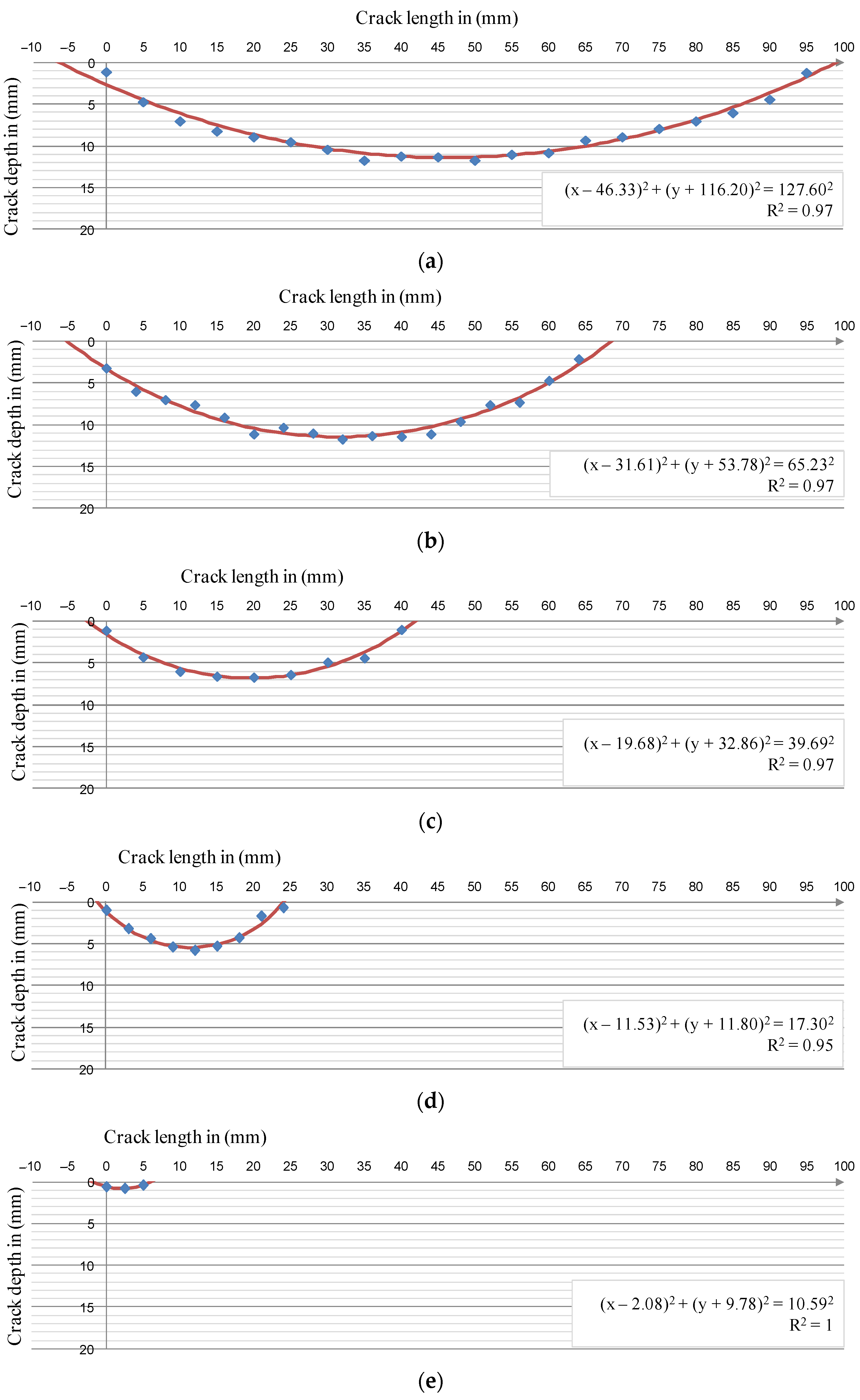
The result of research presented in the article has shown that the depth of a surface crack is strictly dependent on its length. The course of depth changes at successive measurement points along the crack has the shape of an arc of a circle. For this reason, for the performed measurements, an attempt was made to create regression functions of a circle (the curves are shown in
Figure 13).
Obtained graphs and curves indicate a certain discrepancy at both ends of the crack between the regression function and the actual results—the theoretical crack is always a few millimeters longer than the real one. The reasons for this discrepancy were both in the principle of operation of the measuring probe and in the behavior of the target material itself; however, all regression functions showed a very good fit with the measurement results.
Based on the regressive functions of the circles, it was possible to model the radius of the circle depending on the crack length to determine the crack depth; however, the longest (95 mm-long) crack was not taken into account when the model was created. The observations made thus far show that the surface cracks of the disc increased their depth linearly until they reached about 11.5–12 mm (achieved the range of 65–70 mm of crack length). For longer surface cracks, their depth stabilizes approximately at a constant level. Moreover, based on the available documentation, cracks exceeding a length of 70 mm qualify a disc for decommissioning [
37,
38]. The relationship between the crack length and the radius defining its depth is described by Equation (3) [
43]:
where:
r—crack profile defining radius in mm;
lp—crack length in mm.
The function determining the position of the center of the circle on the ordinate axis is described by the Equation (4):
where
b—coordinate of the center of the circle on the ordinate axis.
Adding up both of the above dependencies, the dependence on the crack depth (g
p in mm) depending on the crack length (l
p) was obtained, which is described by Equation (5):
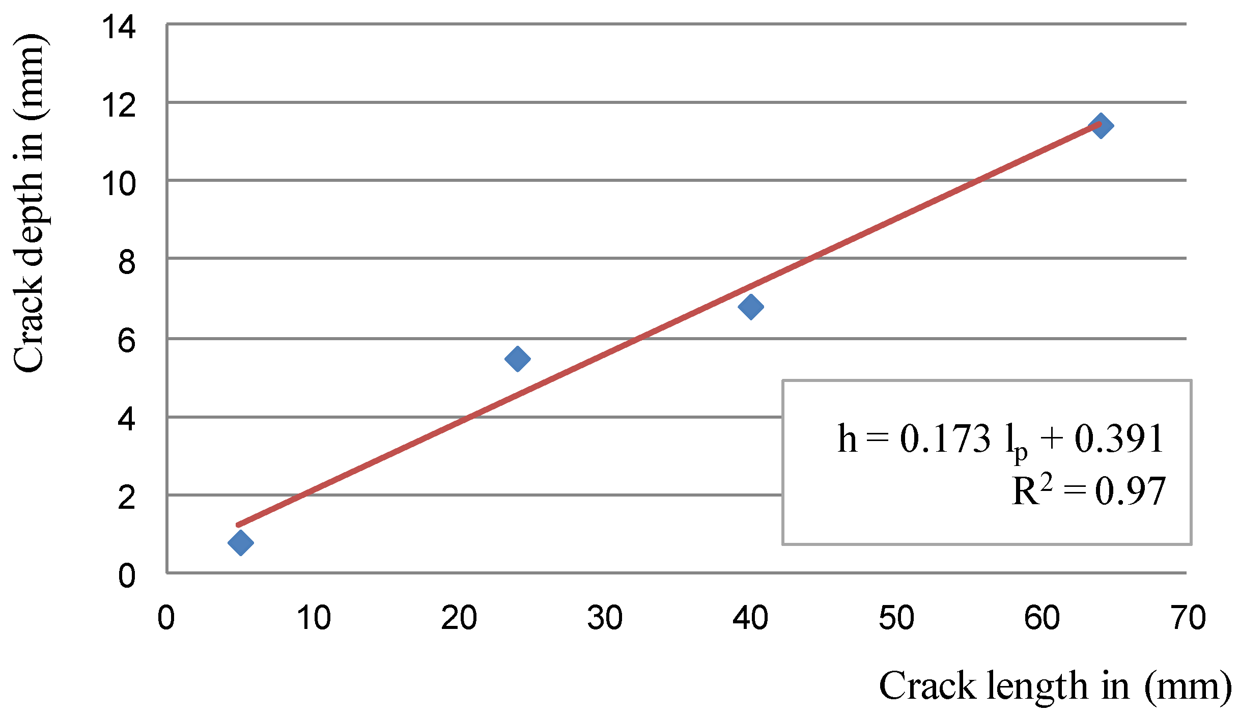
The designated regression functions for estimating the depth of the crack give high coefficients of determination R2 at the level of 0.95–0.97, which proves that the model is well-adjusted to the measurement results. Thus, it can be concluded that the depth of surface cracks, up to 70 mm long, on cast iron brake discs can be determined by simply measuring their lengths.
6. Discussion
Conducted research and analysis of the results allowed for the creation of a simple tool enabling an easy assessment of the technical condition of the brake disc in terms of its suitability for regeneration and further operation.
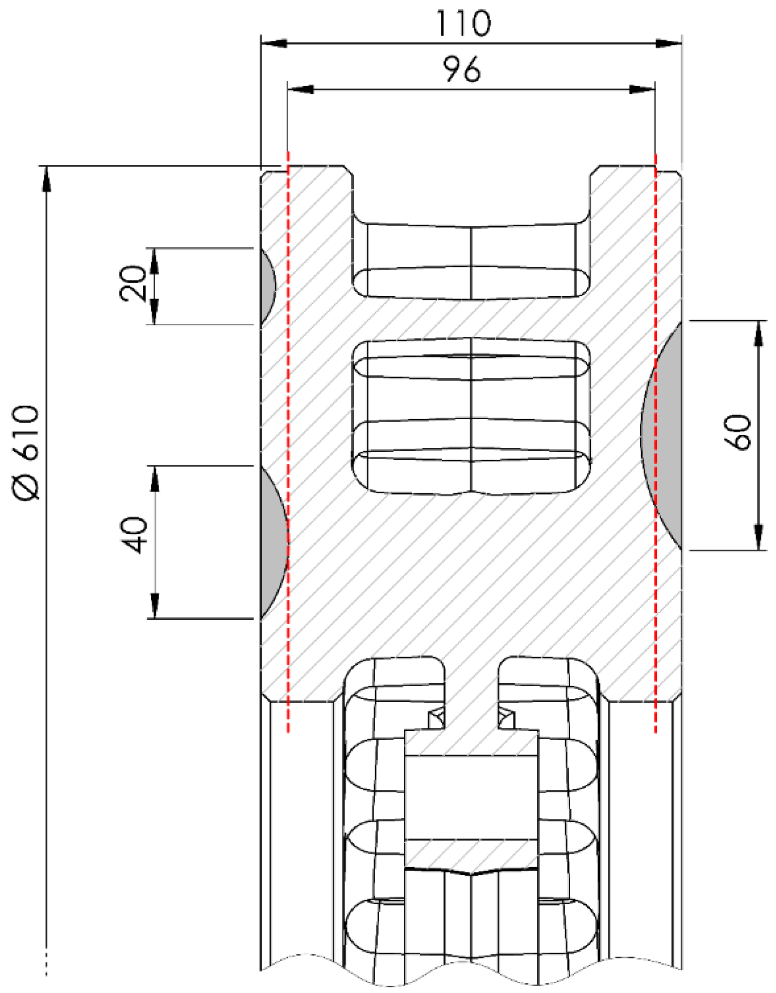
Figure 16 shows examples of 20-, 40-, and 60-mm-long crack cross-sections in a brake disc, with a nominal size of 610 mm × 110 mm, the permissible reduction in the friction ring thickness is 7 mm on each side of the disc.
The longest of the cracks, according to the model, reaching a depth of 10.77 mm, excluded the disc from further use. Even if the disc is regenerated to the minimum thickness, the crack will not be completely eliminated. Shorter cracks, respectively, 3.85 and 7.31 mm in depth, provided that no more serious damage occurs in the remaining cross-sections of the friction rings, could be eliminated using appropriate surface treatment of the disc.
As indicated in [
8], the increase in the crack length with each braking is the greater, the longer the crack is (
Figure 17). Therefore, a reasonable solution would be to regularly turning the brake discs with a small repair dimension in order to eliminate still relatively short cracks; at most a few millimeters. Such a procedure would prevent the penetration of the fracture into the ring cavity due to the ever-faster propagation, thus extending the life time of the brake disc.
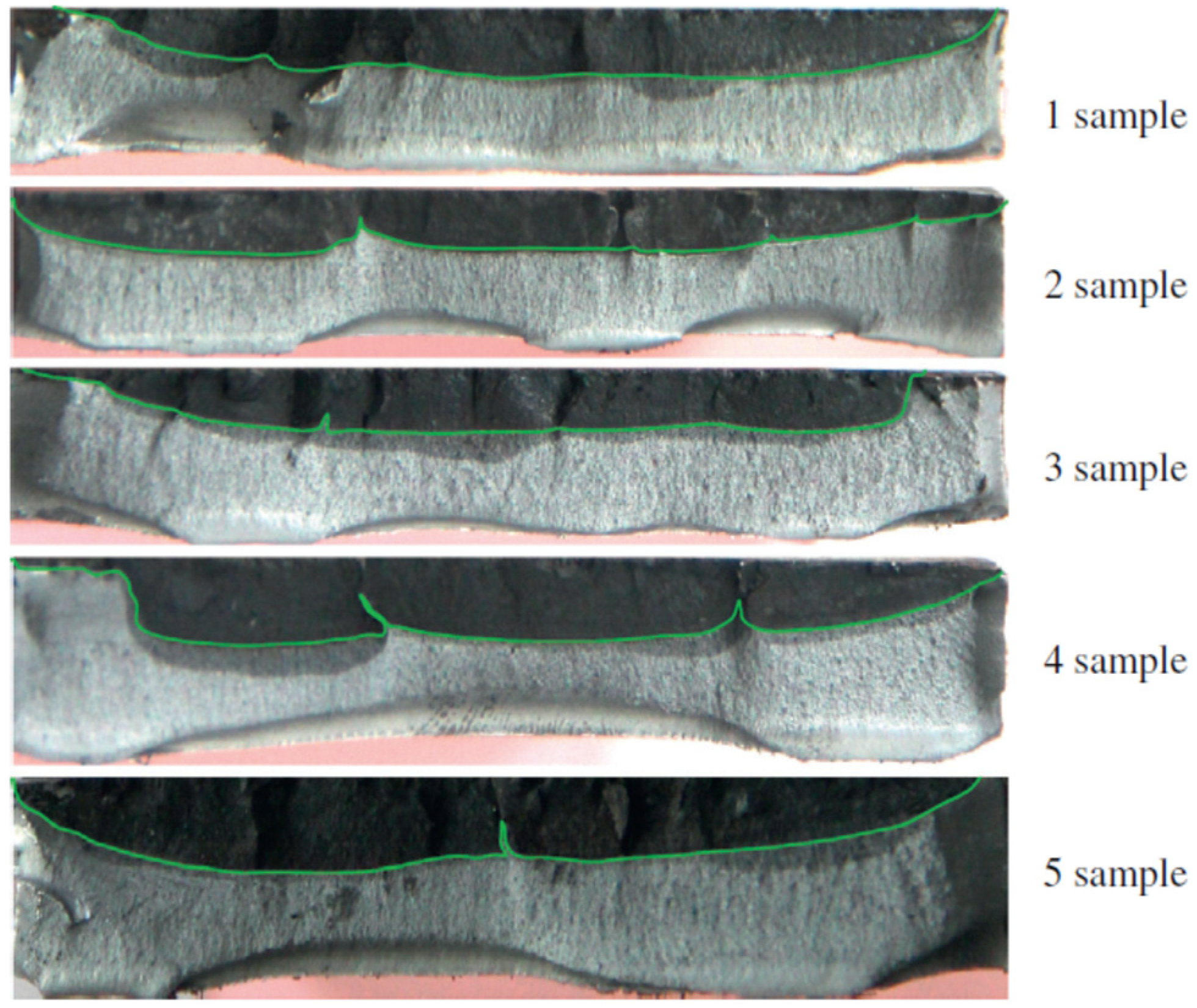
The brake disc material, or, more precisely, its grain, is also important for the method of generating a crack. Since cracks can propagate in two ways: through the growth of a single crack (less frequently) or by propagating and joining several cracks along the same radial axis (more often), due to the different elasticity of the materials used for the discs. The final depth of the crack can differ at different stages of the failure. Finally, a fully developed long crack will reach a similar depth regardless of the mechanism of its formation, and the only difference in the image of the crack will be point “artifacts” in the form of local flattening of the crack (
Figure 18, samples 2–5) delineating the boundaries between primary cracks [
12]. For this reason, the developed method of crack assessment is universal for practical applications. Moreover, it should be pointed out that the results of the crack shape obtained in the tests are consistent with the results of other studies [
5,
6,
7,
8,
11,
12].
The process of replacing brake discs mounted to the axle of a wheelset is very complex—in the case of monolithic discs, it requires pressing the wheel from the axle, and only then it is possible to dismantle the disc. Then, a new disc is mounted and the wheel is pressed on again. Since the wheel mounting must be as rigid as possible, performing this operation on a single set is possible only a few times before the axle mounting is subject to extreme wear—then, in fact, the entire wheel set qualifies for replacement. For this reason, minimizing the number of brake disc replacements is of interest to railway carriers and repair plants. Early elimination of the effects of thermal cracks will reduce the number of premature component replacements, and, thus, in the long term, will reduce the operating costs of rail vehicles.
7. Conclusions
The conducted tests showed that it is possible to determine the depth of a crack on the basis of their length. Cracks that do not disqualify the brake disc from use already at the stage of visual assessment (e.g., due to a crack in the ring along its entire thickness) can be assessed by measuring their length alone.
This article presents two methods of calculating the depth of surface cracks on the basis of a complex and multi-stage research. The first (simpler) method is based on determining the crack depth interval on the basis of many equations for each crack interval at 5 mm intervals. The method was verified by magneto-powder and ultrasonic tests and by drilling the disc in the middle of the fracture in order to measure it. The method allows to estimate the crack with an accuracy of approximately 85%.
In the second method, the surface fracture profile of the brake discs along their length was compared to the arc of a circle. This was proved by fitting the circle equation to the actual depth measurements made with a Karl Deutsch RMG 4015 potential probe.
Dependence of the depth from the crack length up to approx. 70 mm is linear, then it stabilizes and becomes independent of the increase in the crack length. Based on this relationship, it can be concluded that for cracks longer than 70 mm require additional tests for which it will be difficult to obtain a representative group of disks with such failures due to the relatively rare occurrence of such friction ring defects. The accuracy of the second method of crack depth estimation is 95%.
It should be noted that the method of propagation of surface cracks described in the article applies only to brake discs made of cast iron. In the case of steel discs, the course of the depth changes along the fracture length may be different.
Further directions of research on surface cracks should concern a detailed understanding of the phenomenon of hot spots in terms of its identification and modeling. Some studies have noted that this may be related to the shape of the friction material and its contact with the disc. Therefore, work on surface cracks should involve doing brake friction tests (hot-spots phenomenon), material tests and numerical analyses. Further understanding of these issues will have a direct impact on reducing the propagation of surface cracks in railway disc brakes.
Author Contributions
Conceptualization, W.S. and M.J.; methodology, W.S.; software, J.K.; validation, W.S., M.J. and D.U.; formal analysis, W.S.; investigation, W.S. and M.J.; resources, J.K.; data curation, W.S.; writing—original draft preparation, W.S. and D.U.; writing—review and editing, D.U.; visualization, W.S.; supervision, W.S.; project administration, W.S.; funding acquisition, W.S. All authors have read and agreed to the published version of the manuscript.
Funding
This research was funded by Poznan University of Technology, grant numbers 0416/SBAD/0002 and 0414/SBAD/3612.
Institutional Review Board Statement
Not applicable.
Informed Consent Statement
Not applicable.
Data Availability Statement
The data presented in this study are available on request from the corresponding author.
Conflicts of Interest
The authors declare no conflict of interest.
References
- Bagnoli, F.; Dolce, F.; Bernabei, M. Thermal fatigue cracks of fire fighting vehicles gray ironbrake discs. Eng. Fail. Anal. 2009, 16, 152–163. [Google Scholar] [CrossRef]
- Chen, A.; Kienhöfer, F. The failure prediction of a brake disc due to nonthermal or mechanical stresses. Eng. Fail. Anal. 2021, 124, 105319. [Google Scholar] [CrossRef]
- Da Silva, S.A.M.; Kallon, D.V.V. FEA on different disc brake rotors. Procedia Manuf. 2019, 35, 181–186. [Google Scholar] [CrossRef]
- D’Agostino, L.; Di Cocco, V.; Iacovello, F. Overload effects on fatigue cracks in ferritic-pearlitic ductile cast irons. Procedia Struct. Integr. 2016, 2, 3369–3376. [Google Scholar] [CrossRef] [Green Version]
- Li, Z.; Han, J.; Yang, Z.; Pan, L. The effect of braking energy on the fatigue crack propagation in railway brake discs. Eng. Fail. Anal. 2014, 44, 272–284. [Google Scholar] [CrossRef]
- Wang, Z.; Han, J.; Domblesky, J.P.; Li, A.; Fan, X.; Liu, X. Crack propagation and microstructural transformation on the friction surface of a high-speed railway brake disc. Wear 2020, 428–429, 45–54. [Google Scholar] [CrossRef]
- Wu, Y.; Liu, Y.; Chen, H.; Chen, Y.; Li, H.; Yi, W. Microstructure evolution and crack propagation feature in thermal fatigue oflaser-deposited Stellite 6 coating for brake discs. Surf. Coat. Technol. 2019, 358, 98–107. [Google Scholar] [CrossRef]
- Wu, S.C.; Zhang, S.Q.; Xu, Z.W. Thermal crack growth-based fatigue life prediction due to braking for a high-speed railway brake disc. Int. J. Fatigue 2013, 87, 359–369. [Google Scholar] [CrossRef]
- Wu, S.C.; Xu, Z.W.; Yu, C.; Kafka, O.L.; Liu, W.K. A physically short fatigue crack growth approach based on low cycle fatigue properties. Int. J. Fatigue 2017, 103, 185–195. [Google Scholar] [CrossRef]
- Kasem, H.; Brunel, J.F.; Dufrénoy, P.; Siroux, M.; Desmet, B. Thermal levels and subsurface damage induced by the occurrence of hot spots during high-energy braking. Wear 2011, 270, 355–364. [Google Scholar] [CrossRef]
- Li, Z.; Han, J.; Yang, Z.; Li, W. Analyzing the mechanisms of thermal fatigue and phase change of steel used in brake discs. Eng. Fail. Anal. 2015, 57, 202–218. [Google Scholar] [CrossRef]
- Yang, Z.; Han, J.; Li, W.; Li, Z.; Pan, L.; Shi, X. Analyzing the mechanisms of fatigue crack initiationand propagation in CRH EMU brake discs. Eng. Fail. Anal. 2013, 34, 121–128. [Google Scholar] [CrossRef]
- Kumar, M.; Boidin, X.; Desplanques, Y.; Bijwe, J. Influence of various metallic fillers in friction materials on hot-spot appearance during stop braking. Wear 2011, 270, 371–381. [Google Scholar] [CrossRef]
- Hadar-Shanny, S.; Tartakovsky, K.; Rabaev, N.L. Influence of service fluids on carbon-carbon aircrafts brake disc oxidation. Eng. Fail. Anal. 2021, 125, 105403. [Google Scholar] [CrossRef]
- Li, W.; Yang, X.; Wang, S.; Xiao, J.; Hou, Q. Research and prospect of ceramics for automotive disc-brake. Ceram. Int. 2021, 47, 10442–10463. [Google Scholar] [CrossRef]
- Ma, X.; Luan, C.; Fan, S.; Deng, J.; Zhang, L.; Cheng, L. Comparison of braking behaviors between iron- and copper-based powder metallurgy brake pads that used for C/C-SiC disc. Tribol. Int. 2021, 154, 106686. [Google Scholar] [CrossRef]
- Reyes, A.M.; Dela Cruz, C.J.; Diaz, L.J.; Olegario, E.W. Microstructure evaluation oft he damage and wear characteristics of a failed disc brake of a provincial bus. Mater. Today Proc. 2019, 16, 1789–1795. [Google Scholar] [CrossRef]
- Zhao, S.; Yan, Q.; Peng, T.; Zhang, X.; Wen, Y. The braking behaviors of Cu-Based powder metallurgy brake pads mated with C/C-Sic disc for high-speed train. Wear 2020, 448–449, 203237. [Google Scholar] [CrossRef]
- Cai, R.; Zhang, J.; Nie, X.; Tjong, J.; Matthews, D.T.A. Wear mechanism evolution on brake discs for reduced wear and particulate emissions. Wear 2020, 452–453, 203283. [Google Scholar] [CrossRef]
- Dubale, H.; Paramasivam, V.; Gardie, E.; Chekol, E.T.; Selvaraj, S.K. Numerical investigation of thermo-mechanical properties for disc brake using light commercial vehicle. Mater. Today Proc. 2021, in press. [Google Scholar] [CrossRef]
- Jian, Q.; Wang, L.; Shui, Y. Thermal analysis of ventilated brake disc based on heat transfer enhancement of heat pipe. Int. J. Therm. Sci. 2020, 155, 106356. [Google Scholar] [CrossRef]
- Naga Kishore, V.S.; Vineesh, K.P. Temperature evolution in disc brakes during braking oft rain using finite element analysis. Mater. Today Proc. 2021, 41, 1078–1081. [Google Scholar] [CrossRef]
- Pinca-Bretotean, C.; Bhandari, R.; Sharma, C.; Dhakad, S.K.; Cosmin, P.; Sharma, A.K. An investigation of thermal behaviour of brake disk pad assembly with Ansys. Mater. Today Proc. 2021, in press. [Google Scholar] [CrossRef]
- Sai Abhishikt, C.B.N.; Ramachandran, B.; Alekhya, G.N. Design and analysis of disk rotor brake under tribological behaviour of materials. Mater. Today Proc. 2020, 33, 4298–4310. [Google Scholar] [CrossRef]
- Shen, X.; Lu, L.; Zeng, D. Fatigue failure analysis of high strength bolts used for high-speed railway vehicle baking discs. Eng. Fail. Anal. 2020, 115, 104661. [Google Scholar] [CrossRef]
- Yevtushenko, A.; Kuciej, M.; Wasilewski, P. Experimental study on the temperature evolution in the railway brake disc. Theory Appl. Mech. Lett. 2019, 9, 308–311. [Google Scholar] [CrossRef]
- Zhou, S.; Guo, Z.; Bai, X. Fatigue fracture analysis of brake disc bolts under continuous braking condition. Eng. Fail. Anal. 2020, 115, 104588. [Google Scholar] [CrossRef]
- Wu, Y.; Liu, Y.; Chen, H.; Chen, Y.; Xie, D. An investigation into the failure mechanism of several abrasion of high-speed train brake discs on snowy days. Eng. Fail. Anal. 2019, 101, 121–134. [Google Scholar] [CrossRef]
- Konowrocki, R.; Chojnacki, A. Analysis of rail vehicles’ operational reliability in the aspect of safety against derailment based on various methods of determining the assessment criterion. Maint. Reliab. 2020, 22, 73–85. [Google Scholar] [CrossRef]
- Sawczuk, W. Analytical model coefficient of friction (COF) of rail disc brake on the basis of multi-phase stationary tests. Maint. Reliab. 2018, 20, 57–67. [Google Scholar] [CrossRef]
- European Standard EN 14535-3:2015. Railway Applications—Brake Discs for Railway Rolling Stock—Part 3: Brake Discs, Performance of the Disc and the Friction Couple, Classification; British-Adopted European Standard: London, UK, 2015; pp. 12–16.
- European Standard EN 14535-1:2005. Railway Applications—Brake Discs for Railway Rolling Stock—Part 1: Brake Discs Pressed or Shrunk onto the Axle or Drive Shaft, Dimensions and Quality Requirements; British-Adopted European Standard: London, UK, 2005; pp. 22–23.
- UIC Code 541-3: Brakes—Disc Brakes and Their Application—General Conditions for the Approval of Brake Pads, 7th ed.; International Union of Railways: Paris, France, 2010.
- Deepak, J.R.; Bupesh Raja, V.K.; Srikanth, D.; Surendran, H.; Nickolas, M.M. Non-destructive testing (NDT) techniques for low carbon steel welded joints: A review and experimental study. Mater. Today Proc. 2021, 44, 3732–3737. [Google Scholar] [CrossRef]
- García Márquez, F.P.; Peco Chacón, A.M. A review of non-destructive testing on wind turbines blades. Renew. Energy 2020, 161, 998–1010. [Google Scholar] [CrossRef]
- Karl Deutsch Company. Available online: http://www.karldeutsch.pl/images/sklep/185/pliki/ulotka-rmg-4015.pdf (accessed on 18 May 2021).
- Technical Parameters RMG 4015 Instrument. Available online: http://www.1718-show.cn/1718-show_Product_2641296.html (accessed on 18 May 2021).
- Mackin, T.J.; Noe, S.C.; Ball, K.J.; Bedell, B.C.; Bim-Merlr, D.P.; Bingaman, M.C.; Bomleny, D.M.; Chemlir, G.J.; Clayton, D.B.; Evans, H.A.; et al. Thermal cracking in disc brakes. Eng. Fail. Anal. 2002, 9, 63–76. [Google Scholar] [CrossRef]
- Wilkanowicz, W. Maintenance System Documentation—Electric Multiple Unit Type 22WEa—EN76; Koleje Wielkopolskie Spółka z o. o.: Poznan, Poland, 2012; Volume DSU 22WEa 0130-1, pp. 1–111. [Google Scholar]
- Rail Consult Gesellschaft für Verkehrsberatung. Wagon Osobowy Z1 02—Układ Jezdny, t. 2. Dokumentacja Techniczno-Ruchowa; Rail Consult Gesellschaft für Verkehrsberatung: Köln, Germany, 2006; pp. 46–59. [Google Scholar]
- Kowalczyk, J.; Lopato, P.; Psuj, G.; Ulbrich, D. Glass–Adhesive–Steel Joint Inspection Using Mechanic and High Frequency Electromagnetic Waves. Materials 2020, 13, 4648. [Google Scholar] [CrossRef] [PubMed]
- Wlodarczyk, K.; Ulbrich, D.; Selech, J.; Kowalczyk, J. A review of non-destructive evaluation methods of elements of prototype module of drying line used to receive RDF fuel from waste recycling. Procedia Eng. 2017, 192, 959–964. [Google Scholar] [CrossRef]
- Si, T. The equation of motion fort he trajectory of a circling particle with an overdamped circle center. Phys. A 2012, 391, 3054–3060. [Google Scholar] [CrossRef] [Green Version]
Figure 1.
View of a damaged brake disc: (a) cracks on the friction surface of the disc; 1—microcracks, 2—radial cracks, 3—circumferential (longitudinal) cracks, (b) view of fragments of a cracked brake disc.
Figure 1.
View of a damaged brake disc: (a) cracks on the friction surface of the disc; 1—microcracks, 2—radial cracks, 3—circumferential (longitudinal) cracks, (b) view of fragments of a cracked brake disc.
Figure 2.
Images of the cross-sections of the friction ring of the brake disc obtained with a scanning electron microscope [
10]: (
a) cross-section through the area under the macroscopic hot-spot: (1) fracture perpendicular to the friction surface and (2) fracture parallel to the friction surface; (
b) cross-section through the area free from overheating.
Figure 3.
Images of the structure obtained with an optical microscope: (
a) model of the target section with measurement points [
10], (
b) cross-section outside the overheating area [
10], (
c) cross-section on the edge of the overheating area [
10], (
d) cross-section directly in the overheating area: 1—bainite, 2—fine-grained perlite, 3—fine-grained ferrite [
10].
Figure 4.
Instrument for crack depth measurement, type RMG 4015, made by Karl Deutsch: (a) general view and (b) head for cracks perpendicular to the surface.
Figure 4.
Instrument for crack depth measurement, type RMG 4015, made by Karl Deutsch: (a) general view and (b) head for cracks perpendicular to the surface.
Figure 5.
Condition of the friction surface of the T1 (Nodular Cast Iron) disc after the first braking: (a) before penetration testing and (b) after penetration testing (place of cracks marked green).
Figure 5.
Condition of the friction surface of the T1 (Nodular Cast Iron) disc after the first braking: (a) before penetration testing and (b) after penetration testing (place of cracks marked green).
Figure 6.
T2 (Grey Cast Iron) disc surface condition after successive braking (places of cracks marked red): (a) before penetration testing and (b) after penetration testing.
Figure 6.
T2 (Grey Cast Iron) disc surface condition after successive braking (places of cracks marked red): (a) before penetration testing and (b) after penetration testing.
Figure 7.
View of the 610 mm × 110 mm brake disc segment: (a) with the red half-crack line marked, (b) with blind holes to observe the crack depth.
Figure 7.
View of the 610 mm × 110 mm brake disc segment: (a) with the red half-crack line marked, (b) with blind holes to observe the crack depth.
Figure 8.
View of the brake disc section 610 mm × 110 mm: (a) before magneto-particle tests, (b) during tests.
Figure 8.
View of the brake disc section 610 mm × 110 mm: (a) before magneto-particle tests, (b) during tests.
Figure 9.
View of the cross-section of selected microcracks of the brake disc section obtained with the GEKON ultrasonic flaw detector: (a) crack with a depth of 4.3 mm and (b) crack with a depth of 4.9 mm.
Figure 9.
View of the cross-section of selected microcracks of the brake disc section obtained with the GEKON ultrasonic flaw detector: (a) crack with a depth of 4.3 mm and (b) crack with a depth of 4.9 mm.
Figure 10.
One-sided crack on the ring of the railway brake disc: (a) view of the crack and (b) the relationship between the length of the crack and its depth, measured with the RMG 4015 device.
Figure 10.
One-sided crack on the ring of the railway brake disc: (a) view of the crack and (b) the relationship between the length of the crack and its depth, measured with the RMG 4015 device.
Figure 11.
Surface cracks (microcracks) on the ring of the railway brake disc: (a) microcracks mesh on the BK141 segment of the disc, (b) disc cross-section with a 24 mm long crack, (c) disc cross-section with a 40 mm long crack, and (d) disc cross-section and a crack with a length of 64 mm.
Figure 11.
Surface cracks (microcracks) on the ring of the railway brake disc: (a) microcracks mesh on the BK141 segment of the disc, (b) disc cross-section with a 24 mm long crack, (c) disc cross-section with a 40 mm long crack, and (d) disc cross-section and a crack with a length of 64 mm.
Figure 12.
Results of surface crack depth measurements for selected brake discs: (a) crack number histogram for the first disc, (b) dependence of the wMC coefficient (crack length to its depth) for individual classes of crack length intervals of the first disc, (c) crack number histogram for the second disc, and (d) wMC relationship for the second target.
Figure 13.
Crack depth courses depending on their length; blue—measurement results, red—results from the regression model: (a) crack 95 mm long, (b) crack 64 mm long, (c) crack 40 mm long, (d) crack 24 mm long, and (e) crack 5 mm long.
Figure 13.
Crack depth courses depending on their length; blue—measurement results, red—results from the regression model: (a) crack 95 mm long, (b) crack 64 mm long, (c) crack 40 mm long, (d) crack 24 mm long, and (e) crack 5 mm long.
Figure 14.
The relationship between the radius of the arc defining the crack depth and its length; blue—radius values for individual cracks determined from the regression functions of circles, red—linear regression for these values.
Figure 14.
The relationship between the radius of the arc defining the crack depth and its length; blue—radius values for individual cracks determined from the regression functions of circles, red—linear regression for these values.
Figure 15.
The dependence of the depth of the crack on its length; blue—depths determined from the regressive functions of circles, red—linear dependence of the crack depth on its length.
Figure 15.
The dependence of the depth of the crack on its length; blue—depths determined from the regressive functions of circles, red—linear dependence of the crack depth on its length.
Figure 16.
Visualization of three cracks with lengths of 20, 40 and 60 mm on the surface of the fragment of brake disc with dimensions of 610 mm × 110 mm; the red line marks the minimum thickness of the brake disc (96 mm).
Figure 16.
Visualization of three cracks with lengths of 20, 40 and 60 mm on the surface of the fragment of brake disc with dimensions of 610 mm × 110 mm; the red line marks the minimum thickness of the brake disc (96 mm).
Figure 17.
Expected crack length depending on the number of emergency braking cycles performed; the limit crack length of 100 mm was reached in this case after 277,179 braking cycles [
8].
Figure 17.
Expected crack length depending on the number of emergency braking cycles performed; the limit crack length of 100 mm was reached in this case after 277,179 braking cycles [
8].
Figure 18.
Macro morphologies of the crack fractures [
12].
Figure 18.
Macro morphologies of the crack fractures [
12].
Table 1.
Bench test plan.
Table 1.
Bench test plan.
| Type of Test | Speed v (km/h) | Pad Pressure to the Brake Disc N
(kN) | Braking Mass on the Brake Disc M
(t) | Braking
Deceleration a (m/s²) | Number of Brakes |
|---|
| A—local traffic | 40, 80, 100, 120 and 140 | 55 | 7.5 | 0.7 | 72 |
| B—constant braking power of 21, 25 and 34 kW | 80 | variable | 6.3; 7.5; 10 | - | 9 |
| C—fast driving | 225 | 40, 55 | 4.4; 6.3; 7.5 | 0.9 | 18 |
| D1—limit power | 225 | 55 | 6 | 1; 1.1 | 140 |
| D2—limit power | 225 | 55 | 6 | 1; 1.1 | 70 |
| | TOTAL | 309 |
Table 2.
Chemical composition in % of elements for cast iron discs used during the tests.
Table 2.
Chemical composition in % of elements for cast iron discs used during the tests.
| Disc Made of Grey Cast Iron (T2) GJL-250 (GG-25) |
| C | Si | Mn | P | Cu | S | Ce | Sc |
| 3.5 | 1.5 | 0.7 | 0.5 | 0.15 | - | - | - |
| Disc Made of Nodular Cast Iron (T1) GJS-400 (GGG-40) |
| C | Si | Mn | P | Cu | S | Ce | Sc |
| 3.5 | 2.6 | 0.45 | 0.05 | 0.25 | 0.012 | 3.45 | 1.015 |
Table 3.
Ranges of wMC coefficients for different ranges of surface crack lengths.
Table 3.
Ranges of wMC coefficients for different ranges of surface crack lengths.
| No. | Crack Length Range in (mm) | Ratio Range wMC = lp/gp |
|---|
| 1 | 11–15 | 3.5–4.2 |
| 2 | 16–20 | 5.8–6.6 |
| 3 | 21–25 | 6.3–7.1 |
| 4 | 26–30 | 7.2–7.6 |
| 5 | 31–35 | 8.2–8.5 |
| 6 | 36–40 | 9.0–9.1 |
| 7 | 41–45 | 9.0–9.2 |
| 8 | 46–50 | 9.1–9.7 |
| 9 | 51–55 | 10.5–11.4 |
| Publisher’s Note: MDPI stays neutral with regard to jurisdictional claims in published maps and institutional affiliations. |
© 2021 by the authors. Licensee MDPI, Basel, Switzerland. This article is an open access article distributed under the terms and conditions of the Creative Commons Attribution (CC BY) license (https://creativecommons.org/licenses/by/4.0/).


