
Experimental Study on Compression Failure of Composite Laminates with Prefabricated Surface Cracks

Abstract
:1. Introduction
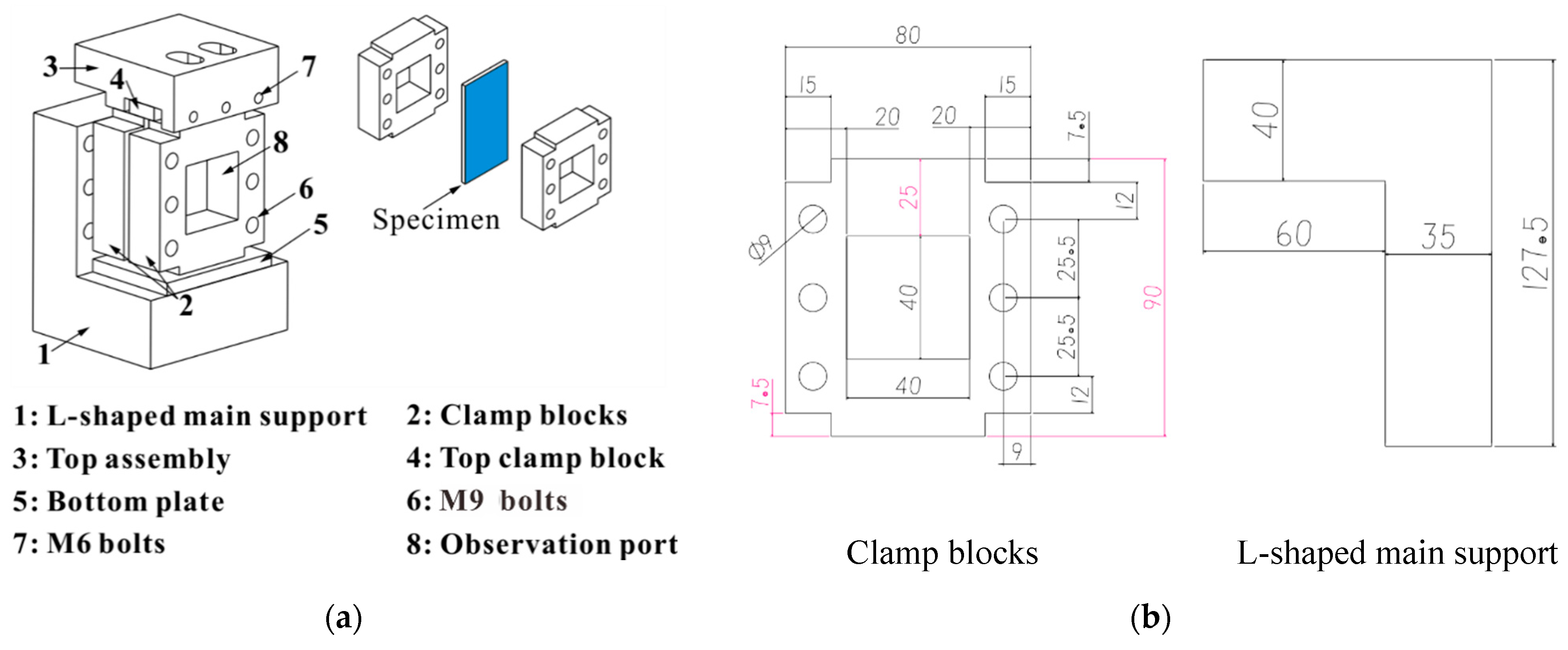
2. Compression Fixture
3. Experiment
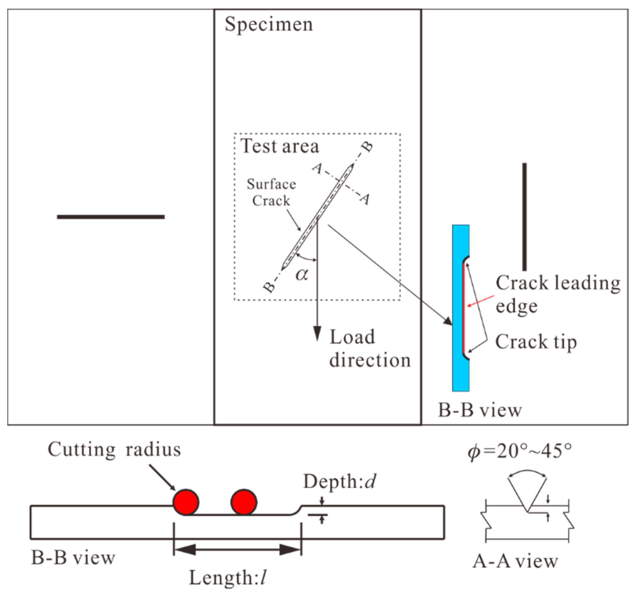
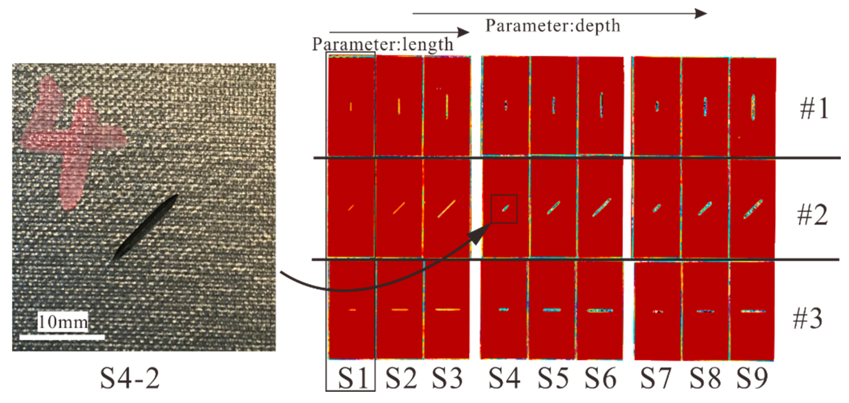
3.1. Specimens
3.2. Experiment Method
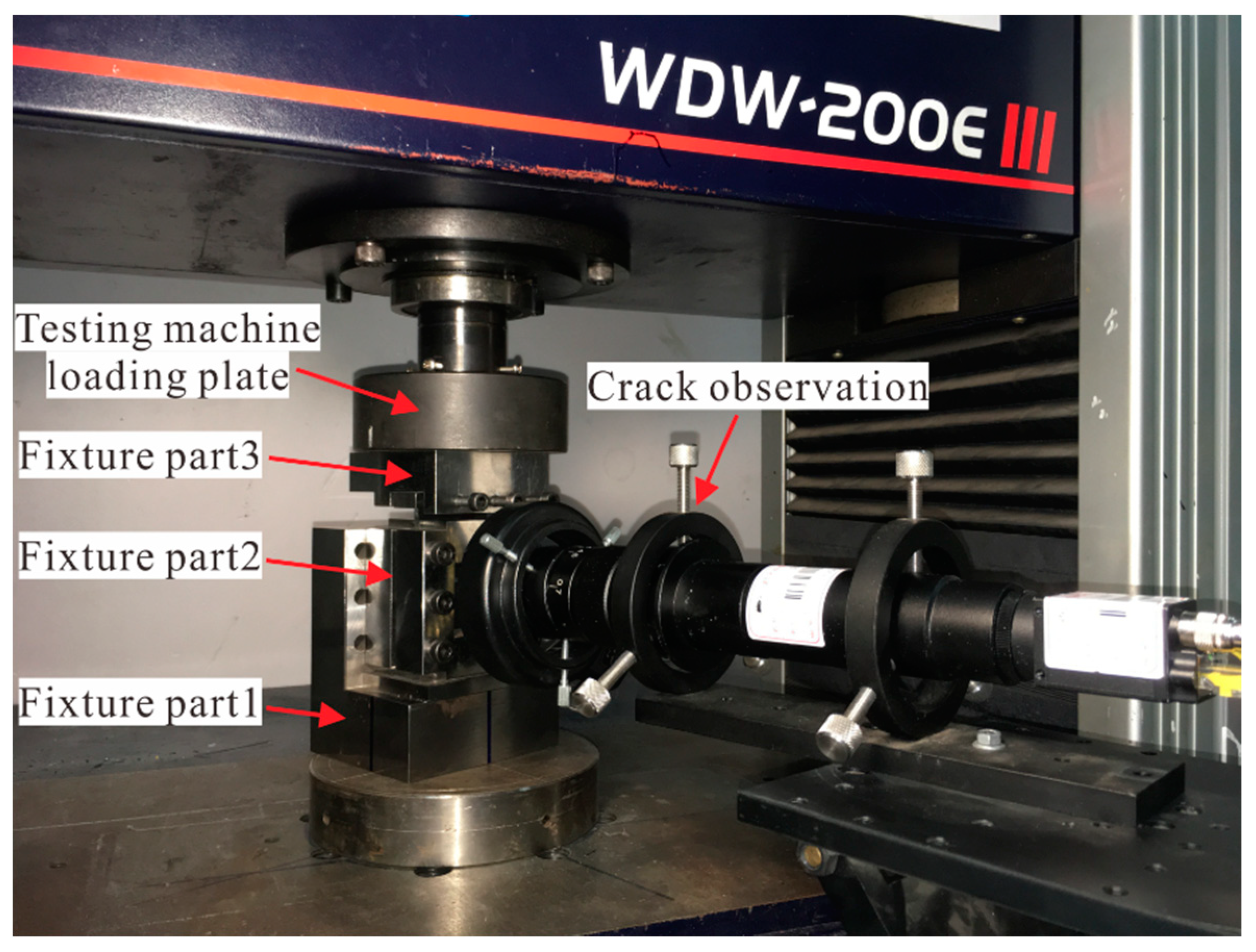
3.2.1. Experiment Equipment
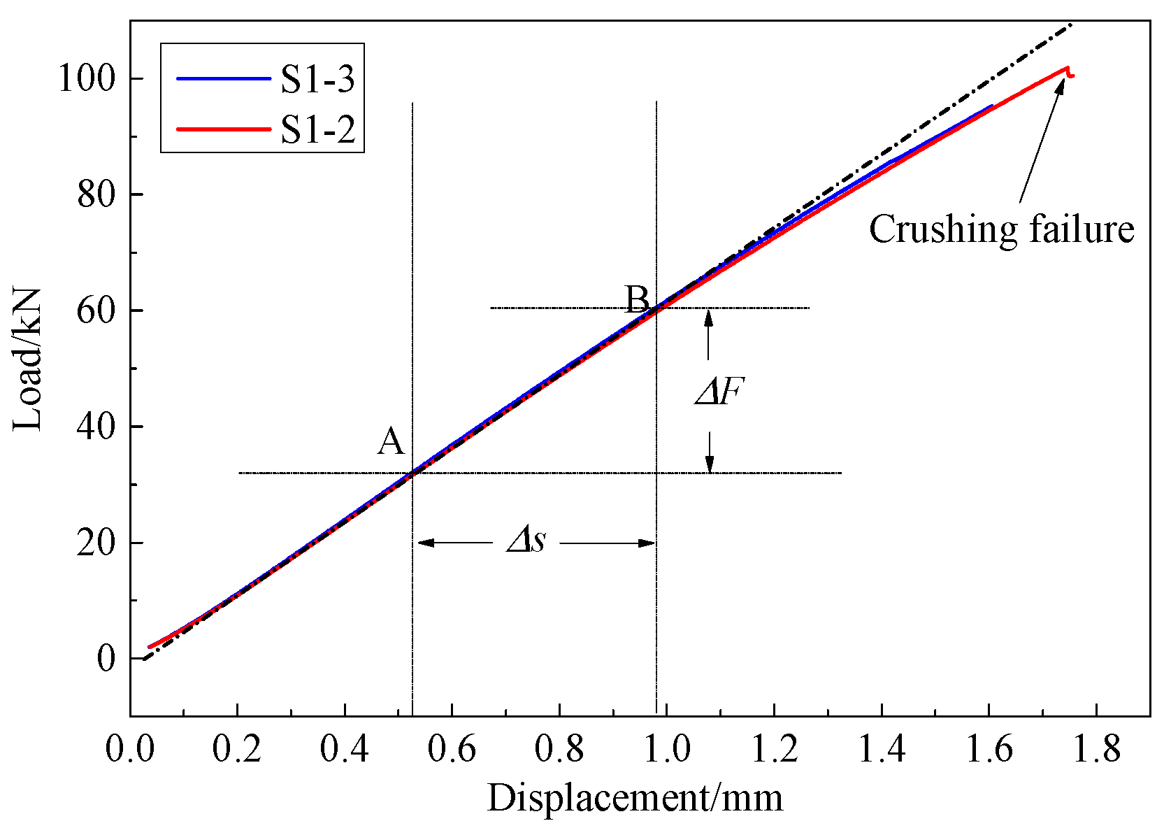
3.2.2. Equivalent Compression Strain Method
3.3. Determination of ε0 and Δε
4. Results and Discussion
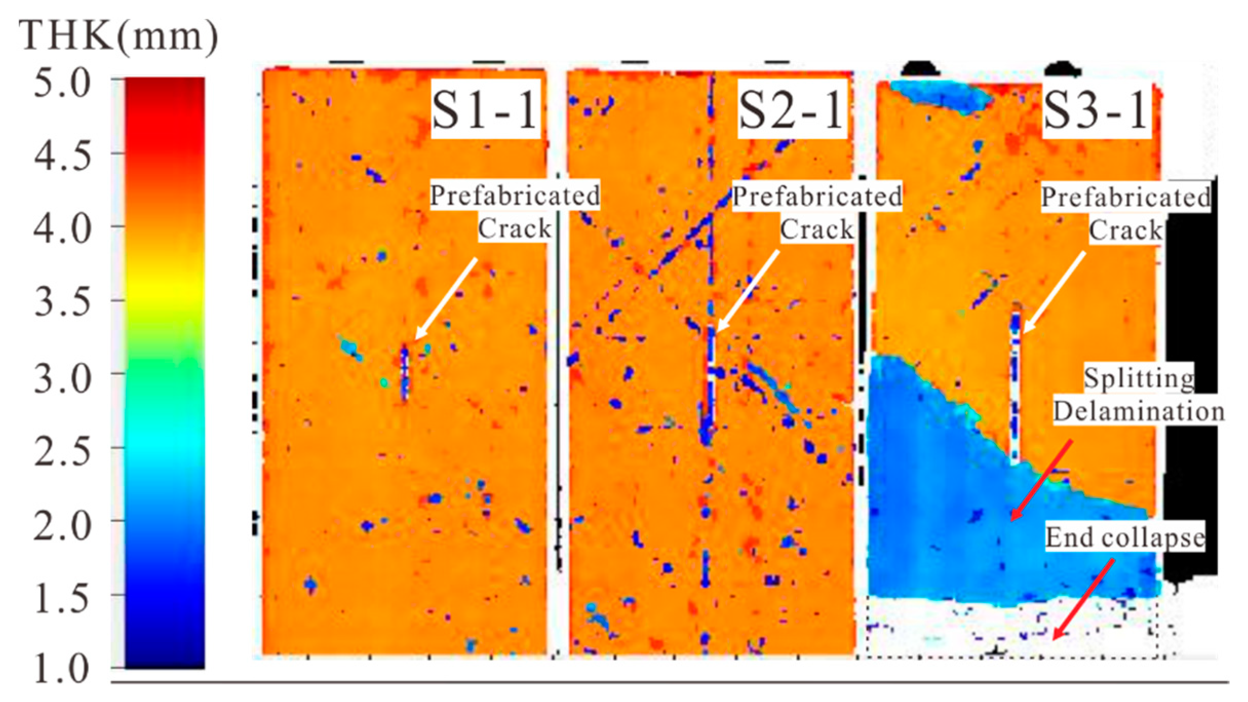
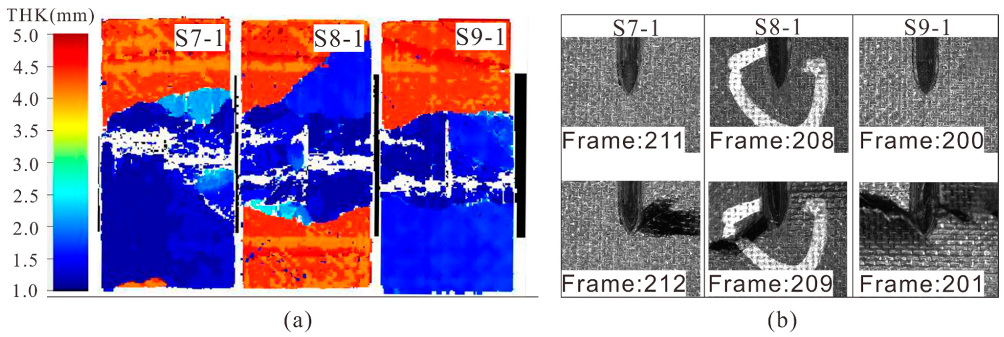
4.1. Compression Failure of Specimens with 0° Cracks
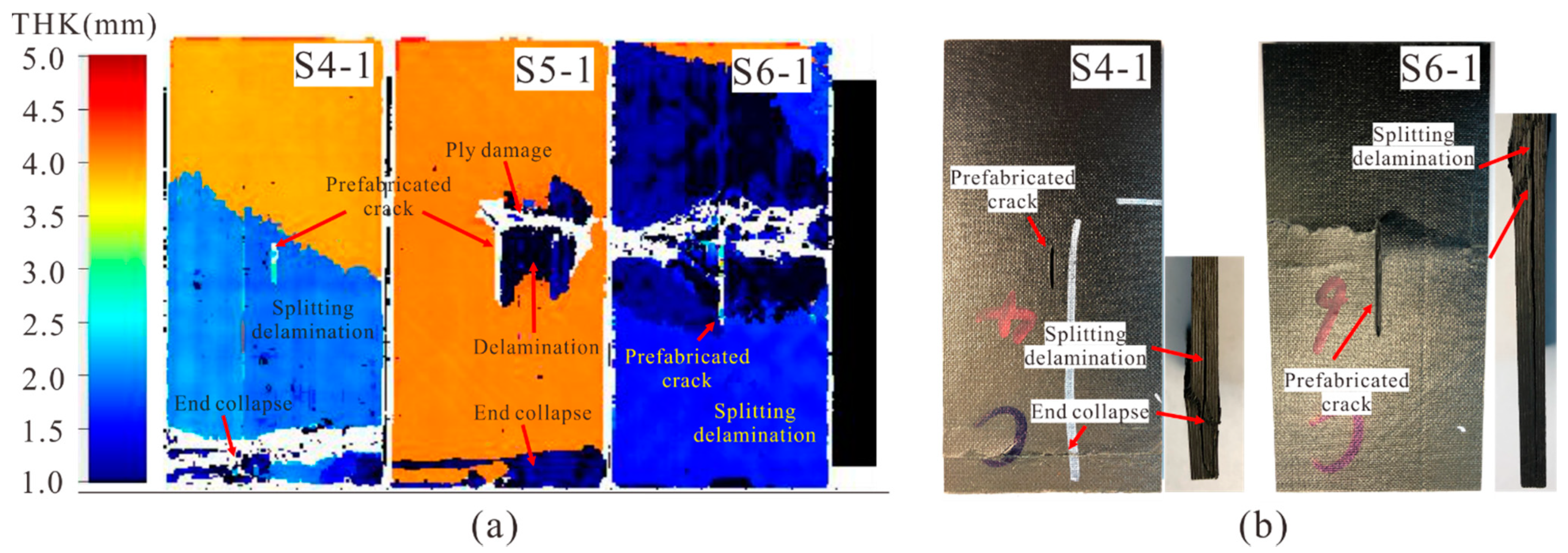
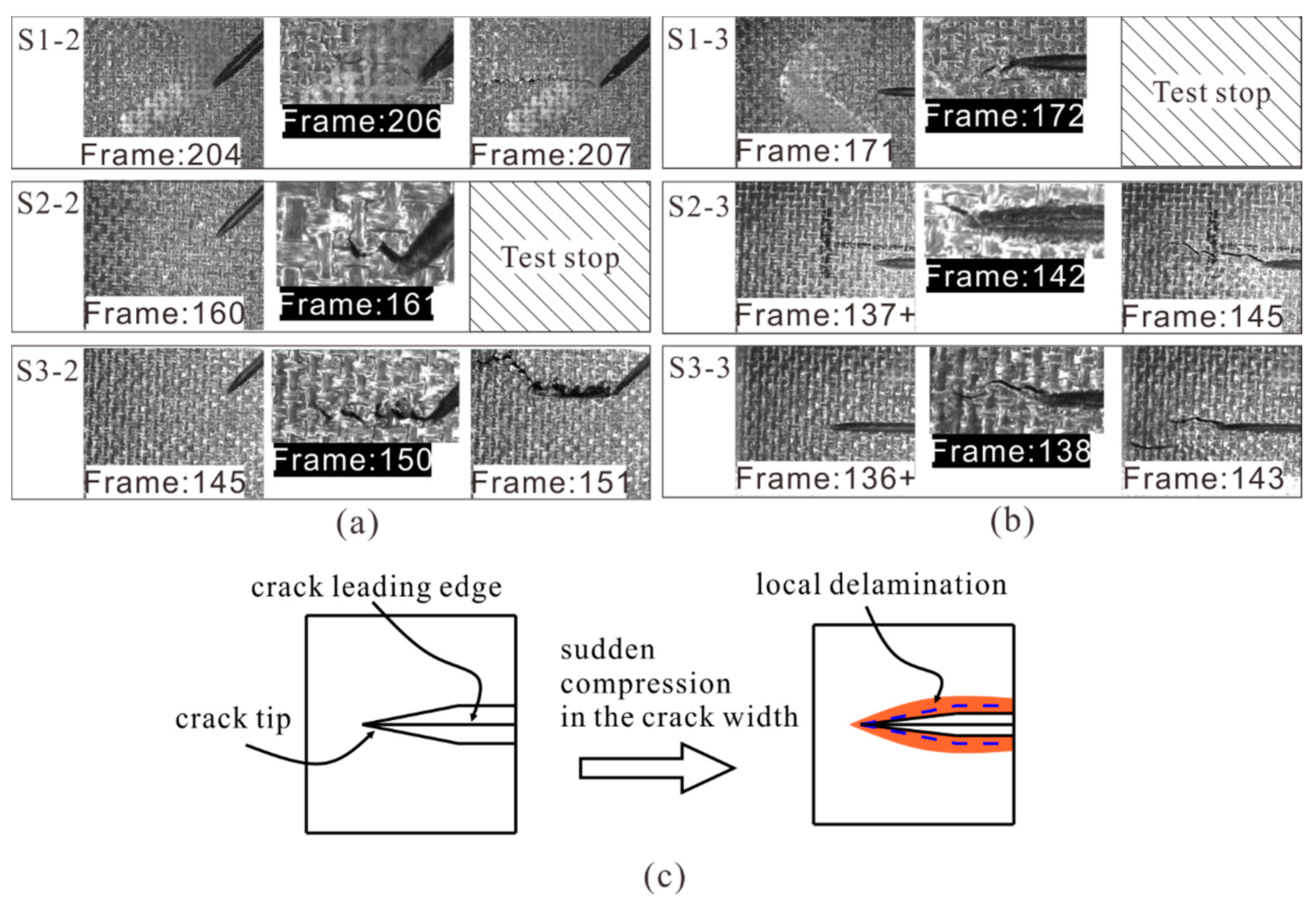
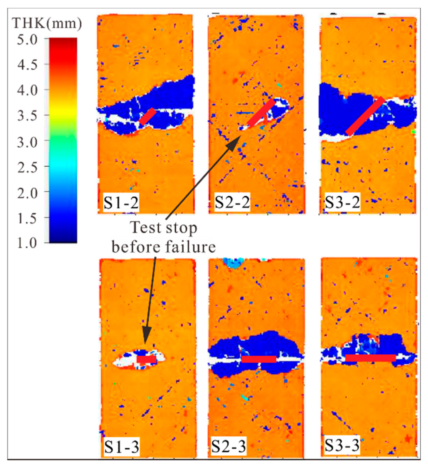
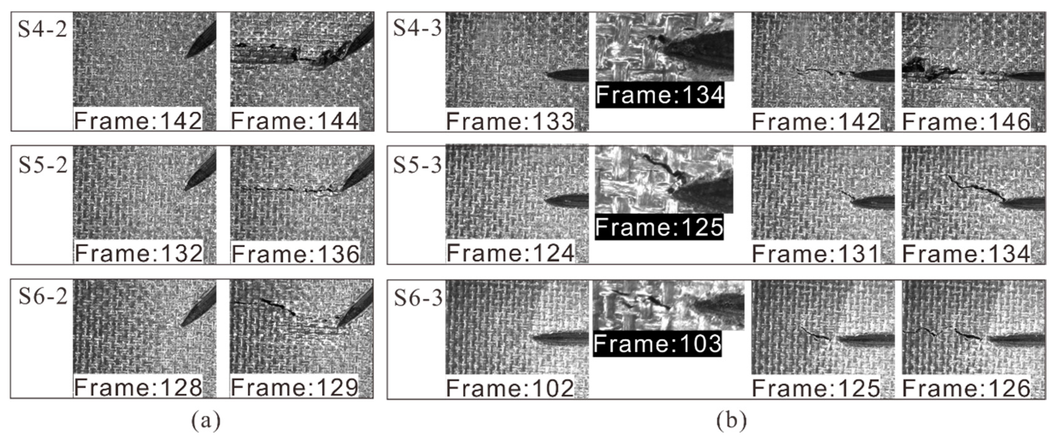
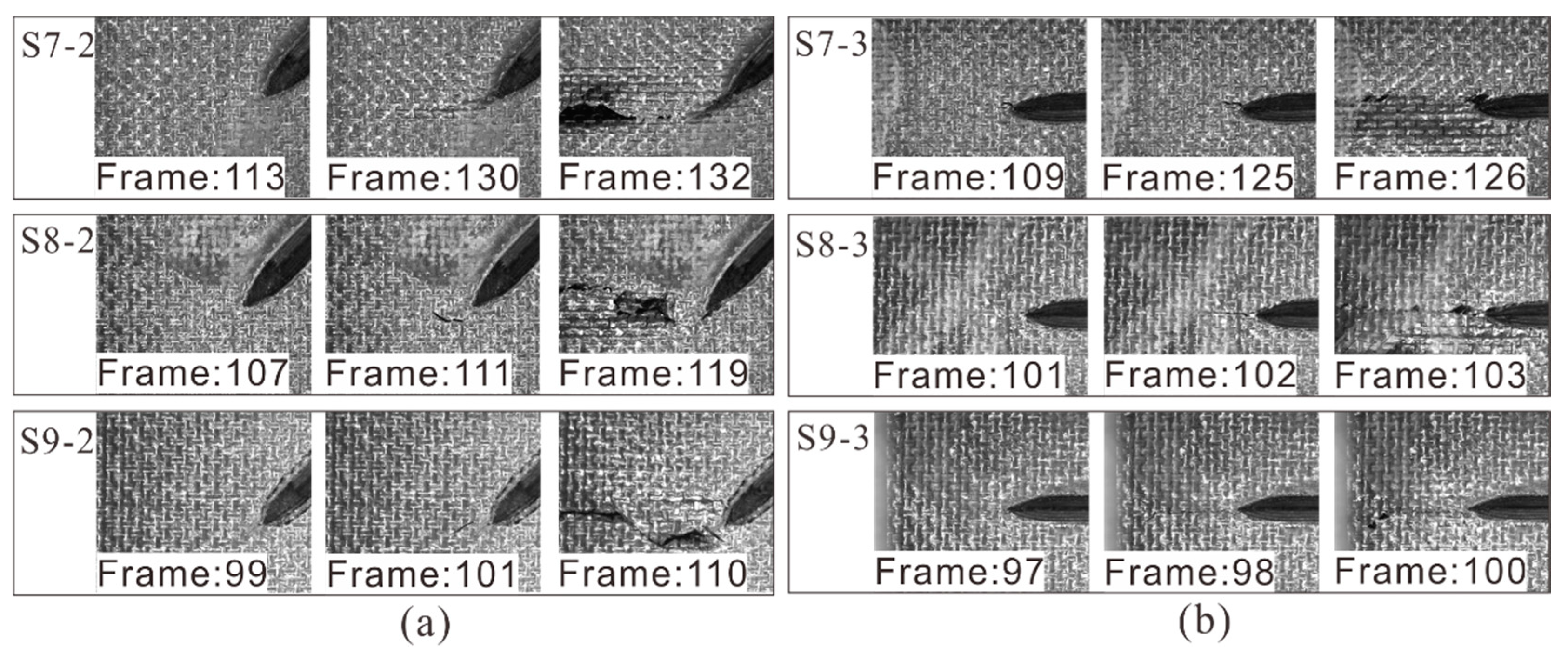
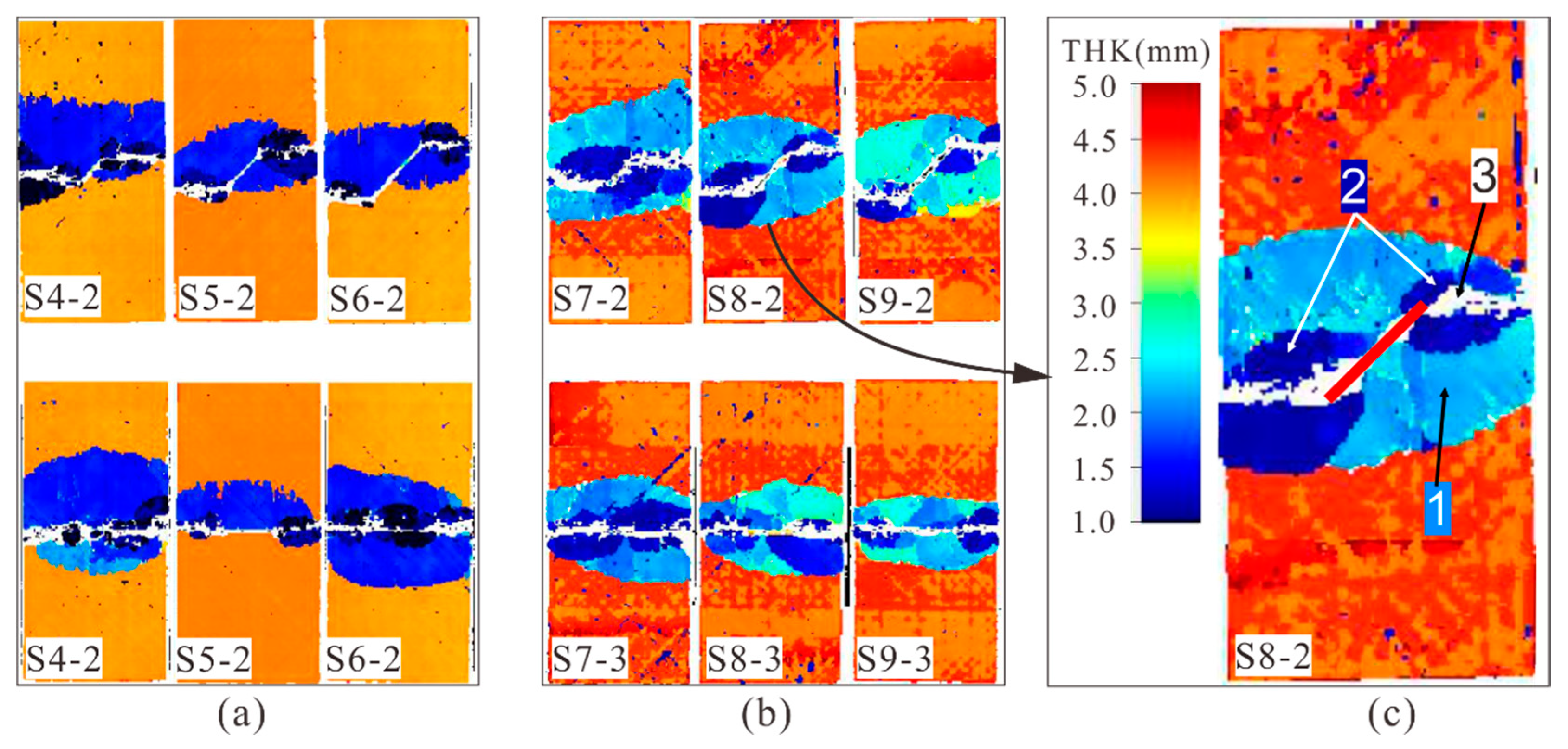
4.2. Crack Propagation of Specimens with 45° and 90° Cracks
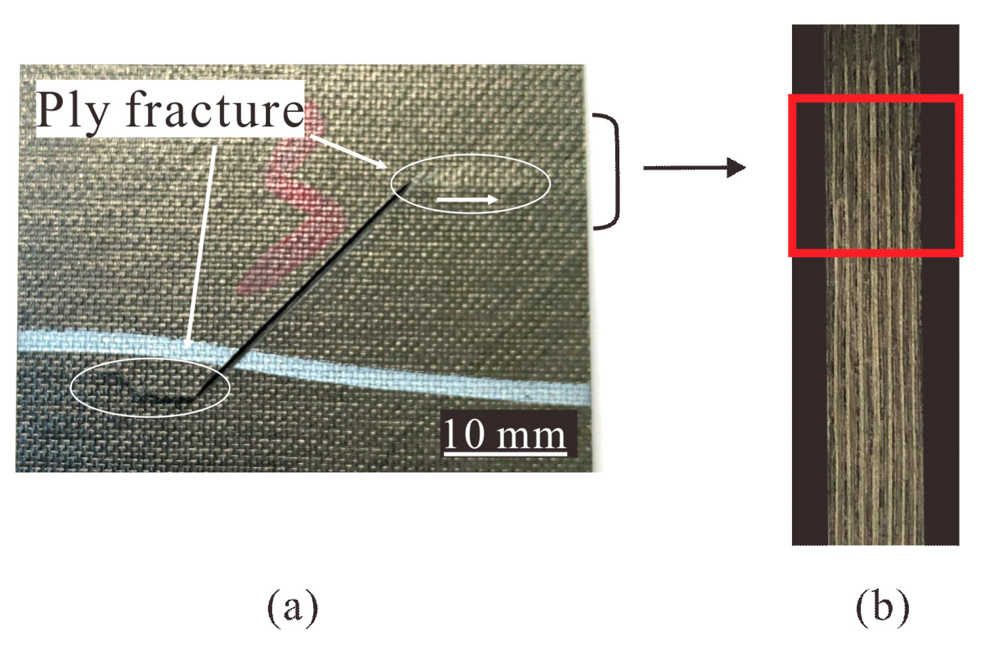
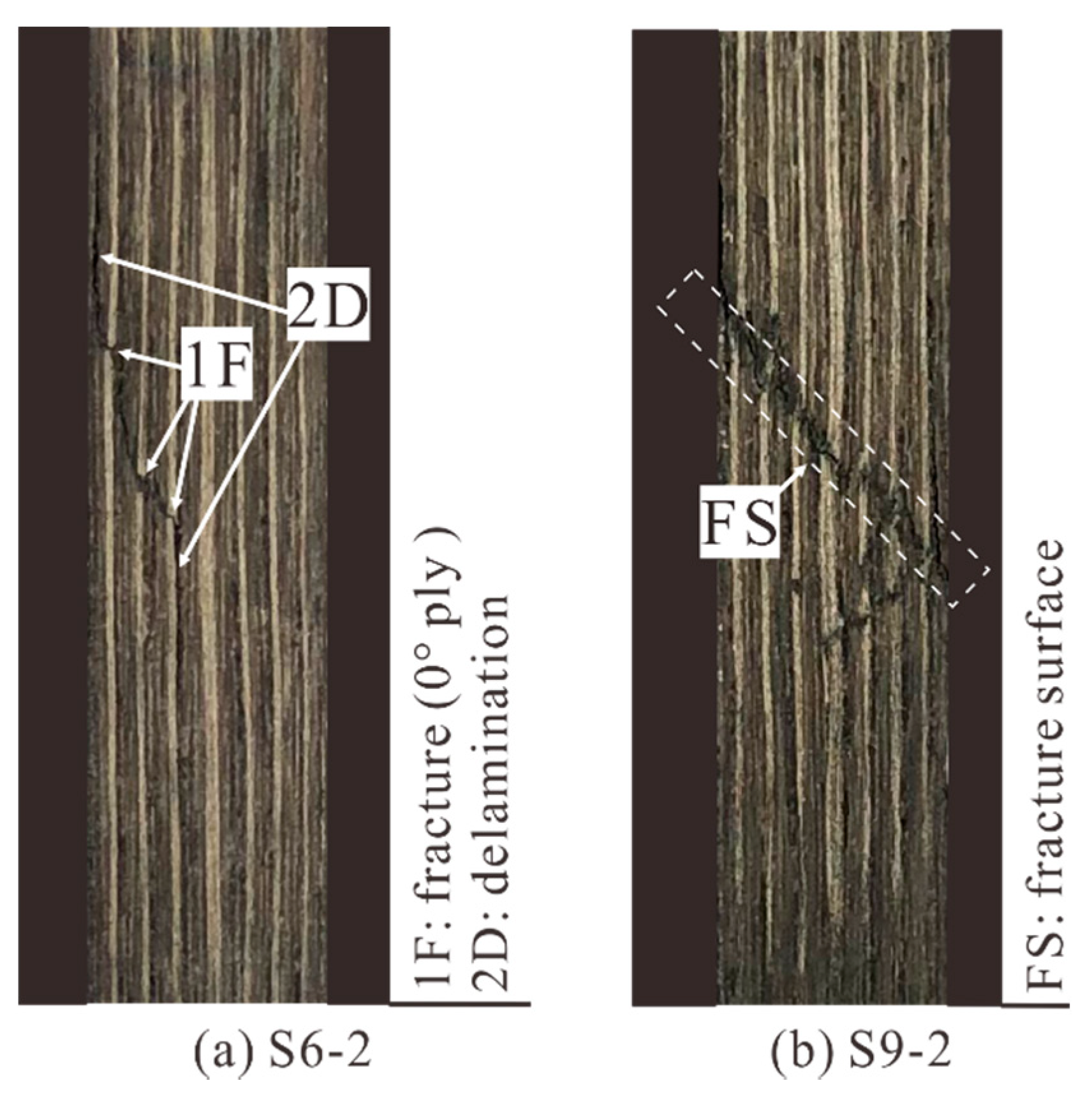
4.3. Typical Compression Failure Modes
5. Conclusions
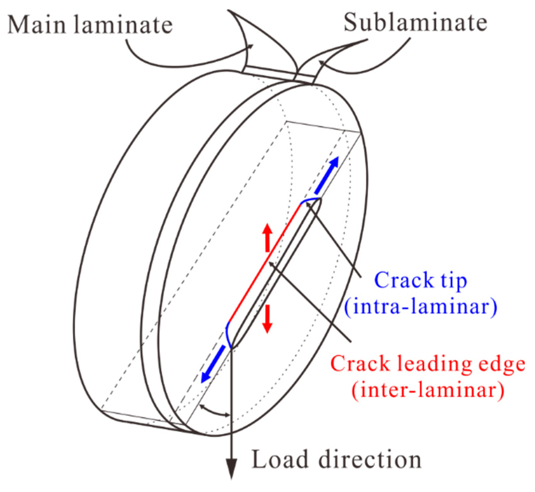
- Two typical crack propagation modes were observed in composite laminates with surface cracks under compression, which were crack tip propagation (intra-laminar) and crack leading edge propagation (inter-laminar). The crack tip propagation led to local ply fracture and delamination, while the crack leading edge propagation caused delamination in a large area.
- The initial strains of the crack tip propagation decreased with the increase of crack depths, lengths, and angles. When the crack angle was 0°, crack tip propagation did not easily occur and the compression failure load was high. When the crack angle was greater than 45°, the effect of the crack angle on crack propagation behaviors and failure modes was weakened.
- The failure of laminates with prefabricated surface cracks under compression was that the crack tips propagated transversely first, and then a large area of delamination occurred from the crack leading edge. When the crack was shallow, the failure mode of the laminate was dominated by the large area of delamination. When the crack was medium or deep, the failure mode of the laminate was dominated by the propagation of crack tip and crack leading edge, which led to the fracture of the sublaminate or the whole laminate.
Author Contributions
Funding
Institutional Review Board Statement
Informed Consent Statement
Data Availability Statement
Conflicts of Interest
Nomenclature
| E11 | Longitudinal elastic modulus |
| E22 | Transverse elastic modulus |
| ν12 | In-plane Poisson’s ratio |
| G12 | In-plane shear modulus |
| l | Crack length |
| d | Crack depth |
| α | Angle between crack and loading direction |
| F0 | Compression test preload |
| Δt | Sampling interval |
| Δε | Strain increment |
| ε0 | Initial strain corresponding to preload |
| k | Slope of load displacement curve |
| A | Extensional stiffness matrix |
| N | In-plane load vector |
References
- Jensen, F.; Falzon, B.; Ankersen, J.; Stang, H. Structural testing and numerical simulation of a 34 m composite wind turbine blade. Compos. Struct. 2006, 76, 52–61. [Google Scholar] [CrossRef]
- Kong, C.; Bang, J.; Sugiyama, Y. Structural investigation of composite wind turbine blade considering various load cases and fatigue life. Energy 2005, 30, 2101–2114. [Google Scholar] [CrossRef]
- Federal Aviation Administration. AC 20-107B. Composite Aircraft Structures; Federal Aviation Administration: Washington, DC, USA, 2009.
- ASTM. Standard Test Method for Compressive Residual Strength Properties of Damaged Polymer Matrix Composite Plates; ASTM International American Society for Testing and Materials: West Conshohocken, PA, USA, 2007. [Google Scholar]
- Sun, X.C.; Hallett, S.R. Failure mechanisms and damage evolution of laminated composites under compression after impact (CAI): Experimental and numerical study. Compos. Part A Appl. Sci. Manuf. 2018, 104, 41–59. [Google Scholar] [CrossRef] [Green Version]
- Rivallant, S.; Bouvet, C.; Abdallah, E.A.; Broll, B.; Barrau, J.-J. Experimental analysis of CFRP laminates subjected to compression after impact: The role of impact-induced cracks in failure. Compos. Struct. 2014, 111, 147–157. [Google Scholar] [CrossRef] [Green Version]
- Bull, D.; Spearing, S.; Sinclair, I. Observations of damage development from compression-after-impact experiments using ex situ micro-focus computed tomography. Compos. Sci. Technol. 2014, 97, 106–114. [Google Scholar] [CrossRef]
- Sebaey, T.A.; González, E.V.; Lopes, C.S.; Blanco, N.; Maimí, P.; Costa, J. Damage resistance and damage tolerance of dispersed CFRP laminates: Effect of the mismatch angle between plies. Compos. Struct. 2013, 101, 255–264. [Google Scholar] [CrossRef]
- Rivallant, S.; Bouvet, C.; Hongkarnjanakul, N. Failure analysis of CFRP laminates subjected to compression after impact: FE simulation using discrete interface elements. Compos. Part A Appl. Sci. Manuf. 2013, 55, 83–93. [Google Scholar] [CrossRef] [Green Version]
- Waas, A.M.; Junghyun, A.; Khamseh, A.R. Compressive failure of notched uniply composite laminates. Compos. Part B Eng. 1998, 29, 75–80. [Google Scholar] [CrossRef]
- Ahn, J.; Waas, A.M. The failure of notched composite laminates under compression using integrated macro-micromechanics model. In Proceedings of the 46th AIAA/ASME/ASCE/AHS/ASC Structures, Structural Dynamics and Materials Conference, Austin, TX, USA, 18–21 April 2005. [Google Scholar]
- Erçin, G.; Camanho, P.; Xavier, J.; Catalanotti, G.; Mahdi, S.; Linde, P. Size effects on the tensile and compressive failure of notched composite laminates. Compos. Struct. 2013, 96, 736–744. [Google Scholar] [CrossRef]
- Yang, Q.; Schesser, D.; Niess, M.; Wright, P.; Mavrogordato, M.; Sinclair, I.; Spearing, S.; Cox, B. On crack initiation in notched, cross-plied polymer matrix composites. J. Mech. Phys. Solids 2015, 78, 314–332. [Google Scholar] [CrossRef]
- Divse, V.; Marla, D.; Joshi, S.S. Finite element analysis of tensile notched strength of composite laminates. Compos. Struct. 2021, 255. [Google Scholar] [CrossRef]
- Riccio, A.; Sellitto, A.; Saputo, S.; Russo, A.; Zarrelli, M.; Lopresto, V. Modelling the damage evolution in notched omega stiffened composite panels under compression. Compos. Part B Eng. 2017, 126, 60–71. [Google Scholar] [CrossRef]
- Vaidya, R.; Sun, C. Fracture criterion for notched thin composite laminates. In Proceedings of the 37th Structure, Structural Dynamics and Materials Conference, Salt Lake City, UT, USA, 15–17 April 1996. [Google Scholar] [CrossRef]
- Serra, J.; Bouvet, C.; Castanié, B.; Petiot, C. Experimental and numerical analysis of carbon fiber reinforced polymer notched coupons under tensile loading. Compos. Struct. 2017, 181, 145–157. [Google Scholar] [CrossRef] [Green Version]
- Enjuto, P.; Lobo, M.; Walker, T.H.; Pena, G.; Cregger, E.; Wanthal, S.P. Investigation of stiffening effects on notch growth trajectory of composite stiffened panels with large transverse notches. AIAA Scitech 2019 Forum 2019. [Google Scholar] [CrossRef]
- Xu, X.; Takeda, S.I.; Aoki, Y.; Hallett, S.R.; Wisnom, M.R. Predicting notched tensile strength of full-scale composite structures from small coupons using fracture mechanics. Compos. Struct. 2017, 180, 386–394. [Google Scholar] [CrossRef] [Green Version]
- Tan, R.; Xu, J.; Sun, W.; Liu, Z.; Guan, Z.; Guo, X. Relationship between matrix cracking and delamination in CFRP cross-ply laminates subjected to low velocity impact. Materials 2019, 12, 3990. [Google Scholar] [CrossRef] [PubMed] [Green Version]
- Gutkin, R.; Pinho, S.; Robinson, P.; Curtis, P. On the transition from shear-driven fibre compressive failure to fibre kinking in notched CFRP laminates under longitudinal compression. Compos. Sci. Technol. 2010, 70, 1223–1231. [Google Scholar] [CrossRef]
- Wind, J.L.; Waas, A.M.; Jensen, H.M. Initiation of failure at notches in unidirectional fiber composites. Compos. Struct. 2015, 122, 51–56. [Google Scholar] [CrossRef]
- Xu, X.; Wisnom, M.R.; Li, X.; Hallett, S.R. A numerical investigation into size effects in centre-notched quasi-isotropic carbon/epoxy laminates. Compos. Sci. Technol. 2015, 111, 32–39. [Google Scholar] [CrossRef] [Green Version]
- Beaumont, M.; Farris, T.; Sun, C. Scratch testing of advanced composite surfaces. Compos. Part A Appl. Sci. Manuf. 1997, 28, 683–686. [Google Scholar] [CrossRef]
- Bora, M.O.; Coban, O.; Sinmazcelik, T.; Gunay, V. Effect of fiber orientation on scratch resistance in unidirectional carbon-fiber-reinforced polymer matrix composites. J. Reinf. Plast. Compos. 2010, 29, 1476–1490. [Google Scholar] [CrossRef]
- Bora, M.Ö.; Fidan, S.; Coban, O.; Yücel, Z. Scratch behavior of glass fiber reinforced polyester matrix composite after solid particle erosion. Polym. Compos. 2015, 36, 1958–1966. [Google Scholar] [CrossRef]
- Petersen, D.R.; El-Hajjar, R.F.; Kabor, B.A. On the tension strength of carbon/epoxy composites in the presence of deep scratches. Eng. Fract. Mech. 2012, 90, 30–40. [Google Scholar] [CrossRef]
- Shams, S.S.; El-Hajjar, R.F. Effects of scratch damage on progressive failure of laminated carbon fiber/epoxy composites. Int. J. Mech. Sci. 2013, 67, 70–77. [Google Scholar] [CrossRef]
- Sun, W.; Guan, Z.; Li, Z. Simulation of low velocity impact induced inter- and intra-laminar damage of composite beams based on XFEM. Appl. Compos. Mater. 2017, 24, 1459–1477. [Google Scholar] [CrossRef]
- Fabbrocino, F.; Funari, M.F.; Greco, F.; Lonetti, P.; Luciano, R.; Penna, R. Dynamic crack growth based on moving mesh method. Compos. Part B Eng. 2019, 174, 107053. [Google Scholar] [CrossRef]
- Martin, E.; Vandellos, T.; Leguillon, D.; Carrère, N. Initiation of edge debonding: Coupled criterion versus cohesive zone model. Int. J. Fract. 2016, 199, 157–168. [Google Scholar] [CrossRef]
- Russell, S.G. A residual strength prediction methodology for composite laminates with surface damage under tensile loading. In Proceedings of the 57th AIAA/ASCE/AHS/ASC Structures, Structural Dynamics, and Materials Conference, San Diego, CA, USA, 4–8 January 2016. [Google Scholar]
- Arikan, H. Failure analysis of (±55°)3 filament wound composite pipes with an inclined surface crack under static internal pressure. Compos. Struct. 2010, 92, 182–187. [Google Scholar] [CrossRef]
- ASTM D695-15. Standard Test Method for Compressive Properties of Rigid Plastics; ASTM International American Society for Testing and Materials: West Conshohocken, PA, USA, 2015. [Google Scholar]
- Jia, L.; Yu, L.; Zhang, K.; Li, M.; Jia, Y.; Blackman, B.; Dear, J. Combined modelling and experimental studies of failure in thick laminates under out-of-plane shear. Compos. Part B Eng. 2016, 105, 8–22. [Google Scholar] [CrossRef]
- Xu, X.; Wisnom, M.R.; Mahadik, Y.; Hallett, S.R. An experimental investigation into size effects in quasi-isotropic carbon/epoxy laminates with sharp and blunt notches. Compos. Sci. Technol. 2014, 100, 220–227. [Google Scholar] [CrossRef] [Green Version]


| Specimen | l (mm) | d (mm) | α (°) | |
|---|---|---|---|---|
| S1-1~3 | 10 | 0.8 | (shallow) | 0, 45, 90 |
| S2-1~3 | 18 | 0.8 | 0, 45, 90 | |
| S3-1~3 | 26 | 0.8 | 0, 45, 90 | |
| S4-1~3 | 10 | 1.6 | (medium) | 0, 45, 90 |
| S5-1~3 | 18 | 1.6 | 0, 45, 90 | |
| S6-1~3 | 26 | 1.6 | 0, 45, 90 | |
| S7-1~3 | 10 | 2.4 | (deep) | 0, 45, 90 |
| S8-1~3 | 18 | 2.4 | 0, 45, 90 | |
| S9-1~3 | 26 | 2.4 | 0, 45, 90 |
| Specimen | Failure Mode | Note |
|---|---|---|
| S1-1 | Not conducted | Unaccepted mode |
| S2-1 | Not conducted | Unaccepted mode |
| S3-1 | End crushing | Unaccepted mode |
| S4-1 | End crushing | Unaccepted mode |
| S5-1 | End crushing | Unaccepted mode |
| S6-1 | Critical failure mode | Accepted mode |
| S7-1 | Failure in the test area | Accepted mode |
| S8-1 | Failure in the test area | Accepted mode |
| S9-1 | Failure in the test area | Accepted mode |
Publisher’s Note: MDPI stays neutral with regard to jurisdictional claims in published maps and institutional affiliations. |
© 2021 by the authors. Licensee MDPI, Basel, Switzerland. This article is an open access article distributed under the terms and conditions of the Creative Commons Attribution (CC BY) license (https://creativecommons.org/licenses/by/4.0/).
Share and Cite
Sun, W.; Ouyang, T.; Li, Z.; Li, Y. Experimental Study on Compression Failure of Composite Laminates with Prefabricated Surface Cracks. Materials 2021, 14, 3616. https://doi.org/10.3390/ma14133616
Sun W, Ouyang T, Li Z, Li Y. Experimental Study on Compression Failure of Composite Laminates with Prefabricated Surface Cracks. Materials. 2021; 14(13):3616. https://doi.org/10.3390/ma14133616
Chicago/Turabian StyleSun, Wei, Tian Ouyang, Zengshan Li, and Yan Li. 2021. "Experimental Study on Compression Failure of Composite Laminates with Prefabricated Surface Cracks" Materials 14, no. 13: 3616. https://doi.org/10.3390/ma14133616
APA StyleSun, W., Ouyang, T., Li, Z., & Li, Y. (2021). Experimental Study on Compression Failure of Composite Laminates with Prefabricated Surface Cracks. Materials, 14(13), 3616. https://doi.org/10.3390/ma14133616