
Cyclic Behavior of Reinforced High Strain-Hardening UHPC under Axial Tension


Abstract
:1. Introduction
2. Experimental Program
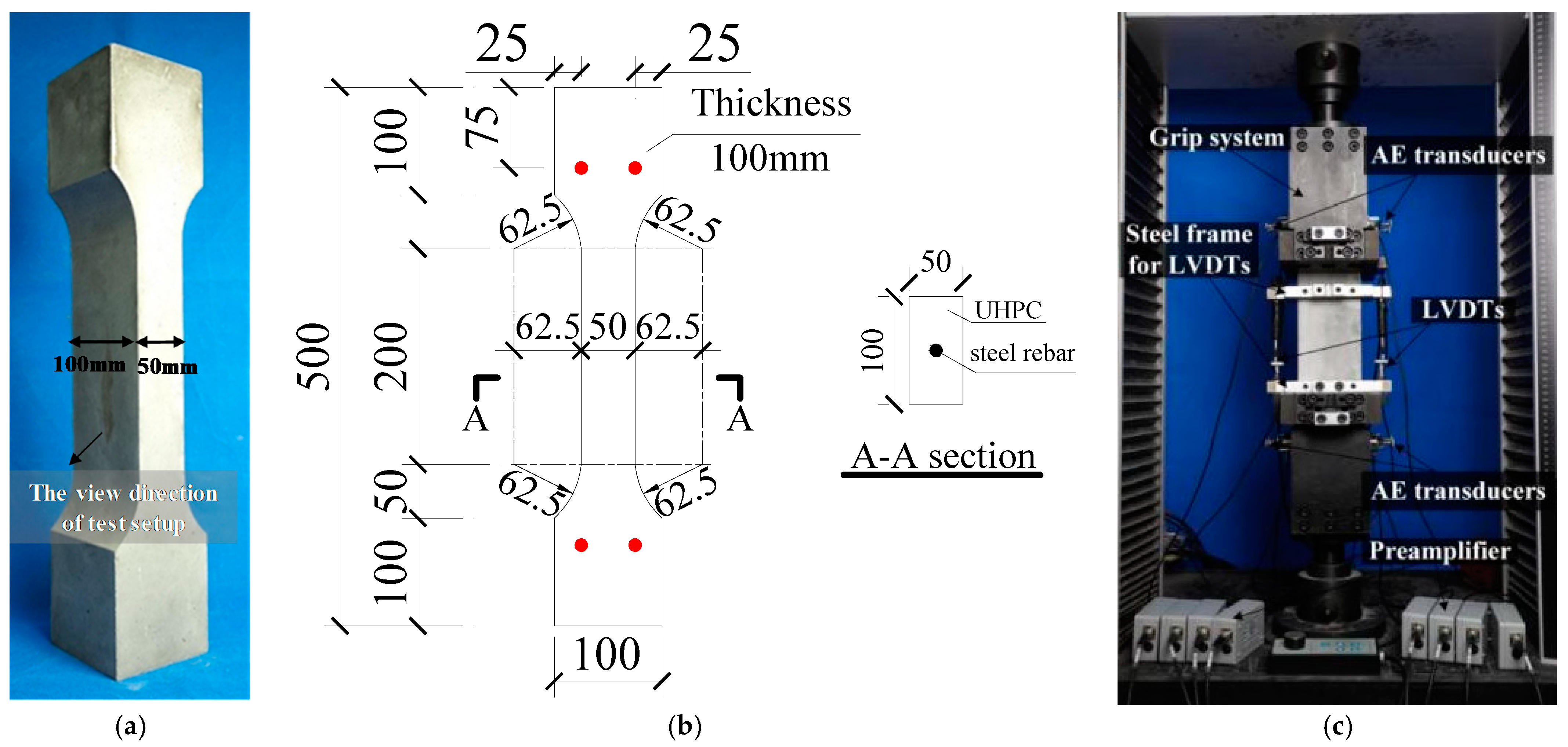
2.1. Description of Test Specimens
2.2. Materials
2.2.1. UHPC
2.2.2. Steel Rebar
2.3. Test Setup, Instrumentation and Test Procedure
2.4. Loading Scheme
3. Test Results
3.1. Failure Pattern
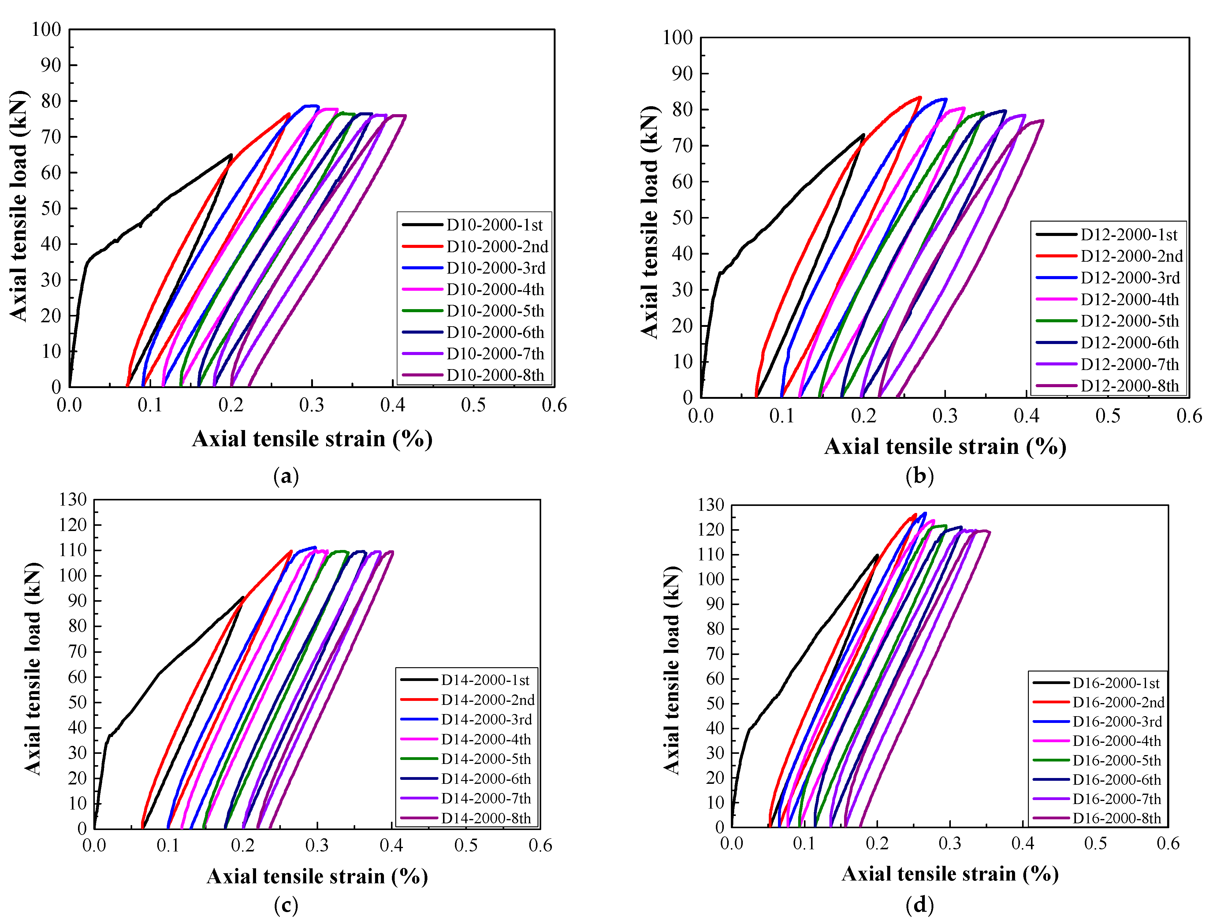
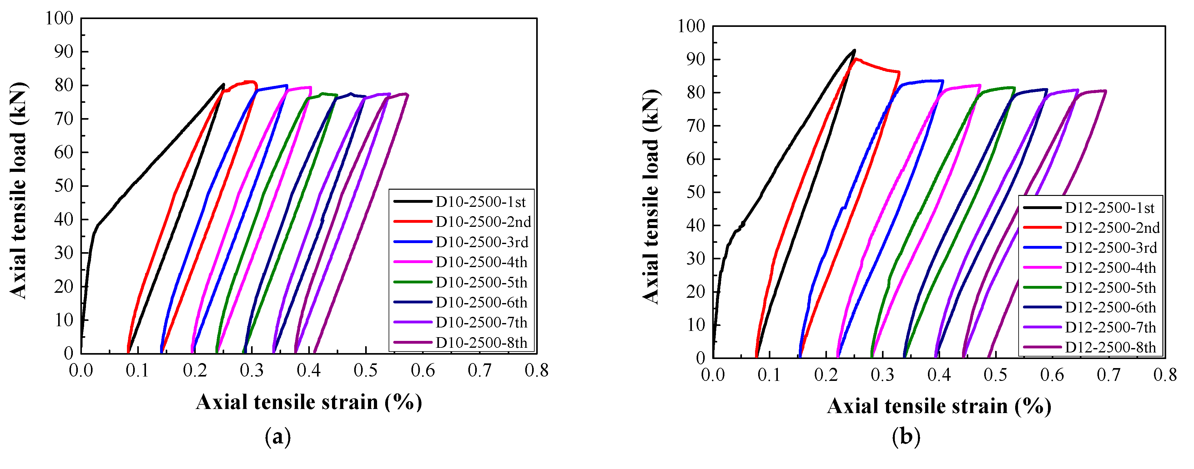
3.2. Load–Strain Relationship
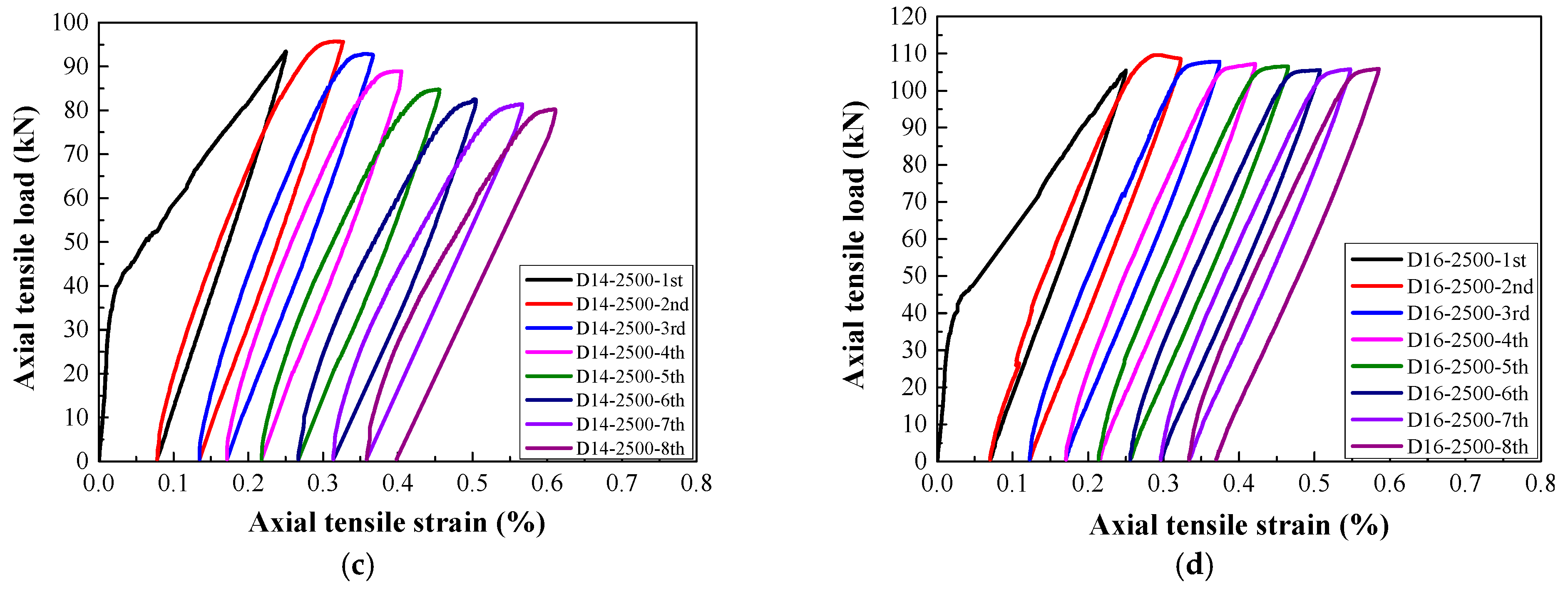
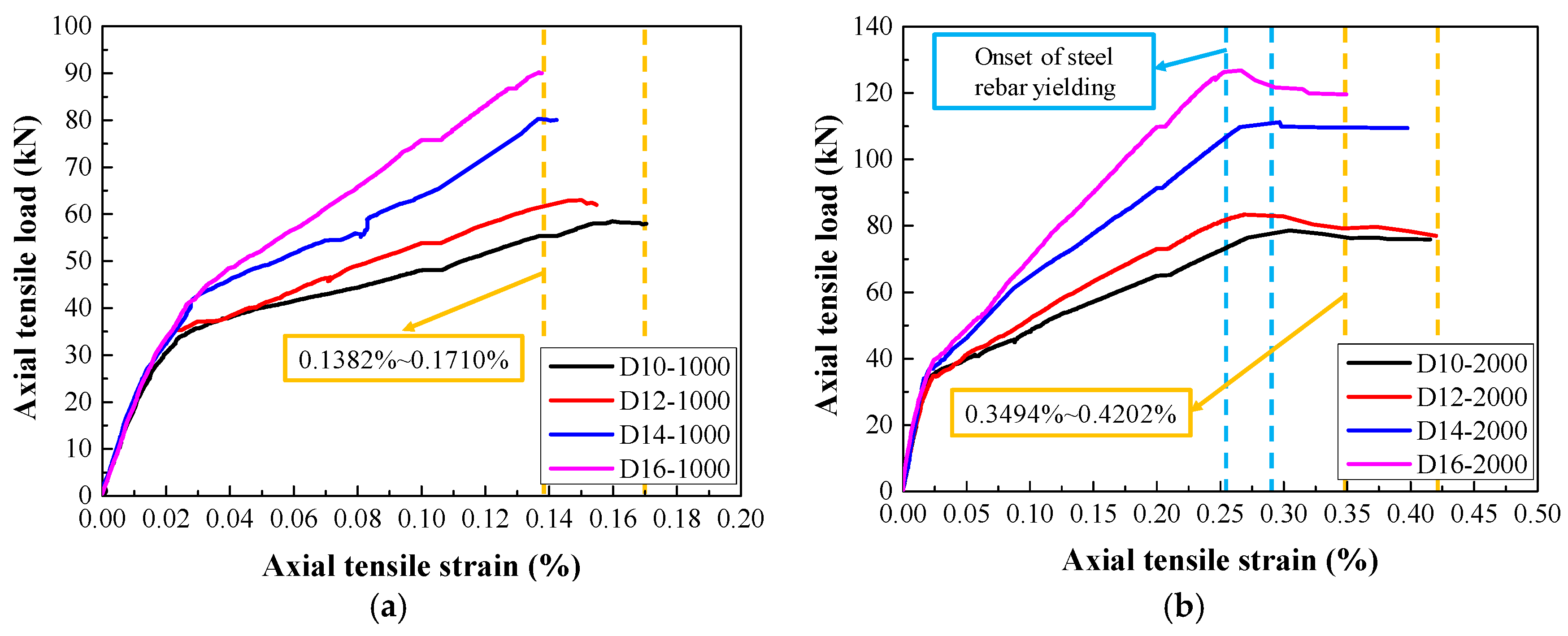
3.3. Envelope Curves
3.4. Residual Strain
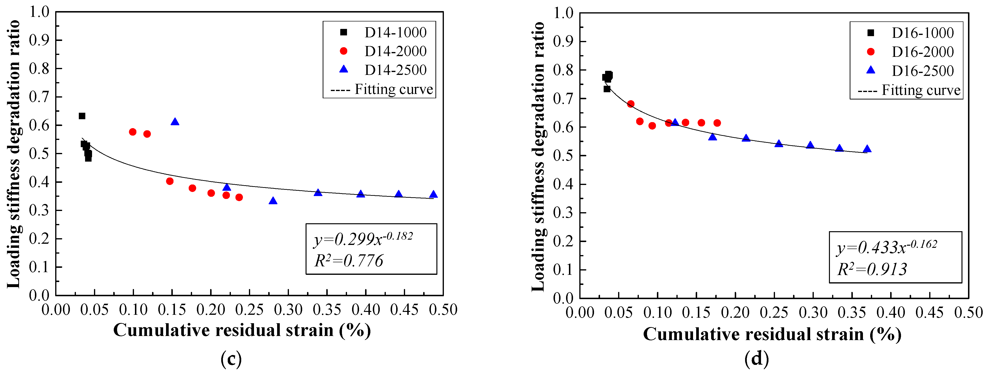
3.5. Stiffness Degradation
3.6. Damage Evolution Process Based on AE Locating
4. Discussion
4.1. Tension-Stiffening Effect
4.2. Stiffness Degradation Mechanism
5. Conclusions
- (1)
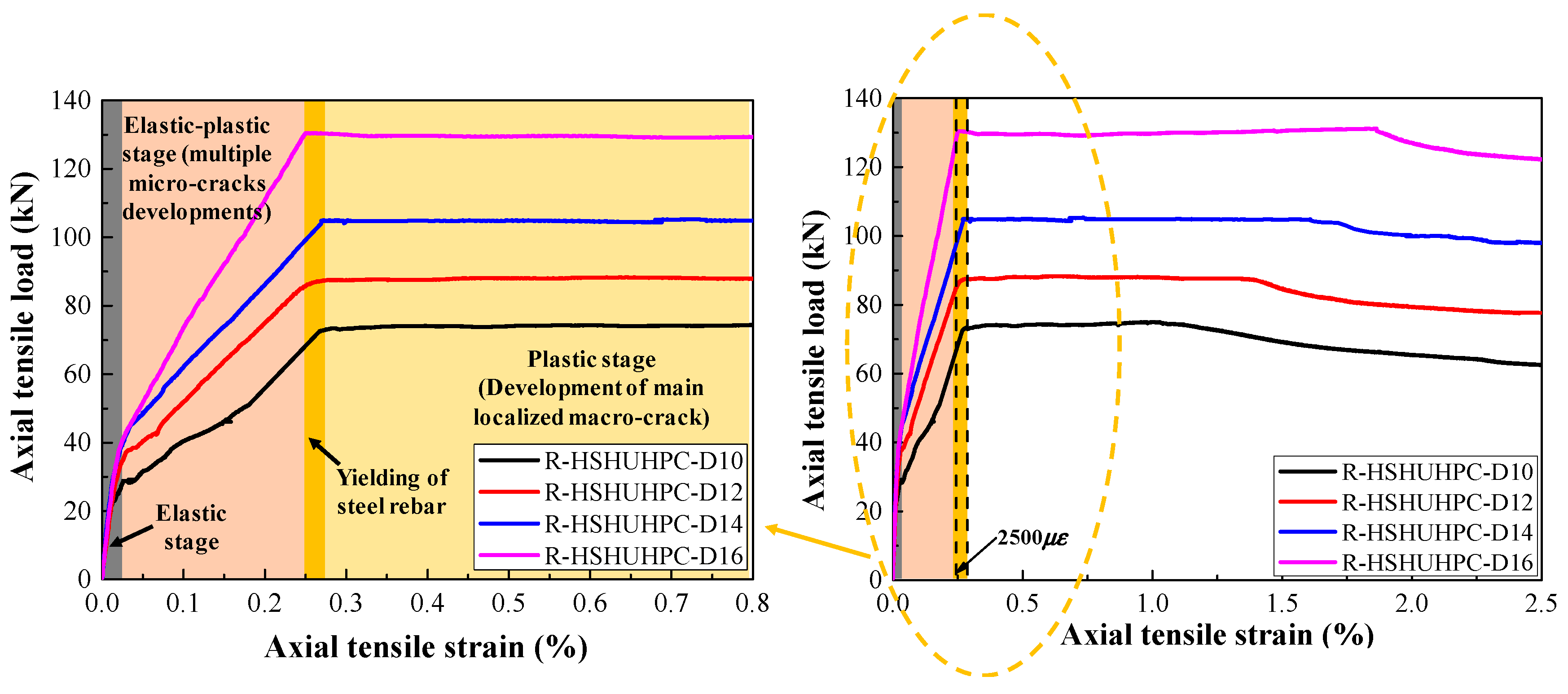
- For a target strain of 1000 με in each cycle, the typical failure of steel-reinforced HSHUHPC exhibited uniformly distributed multiple micro-cracks due to the excellent crack width control ability of HSHUHPC, while for the target strain of 2000 and 2500 με in each cycle, the typical failure pattern exhibited a single, localized macro-crack in conjunction with a sprinkling of narrow and closely spaced micro-cracks due to the inclusion of steel fibers, which intensified the strain concentration in the embedded steel rebar. AE source locating technology provides strong evidence for the damage distribution of the whole loading process.
- (2)
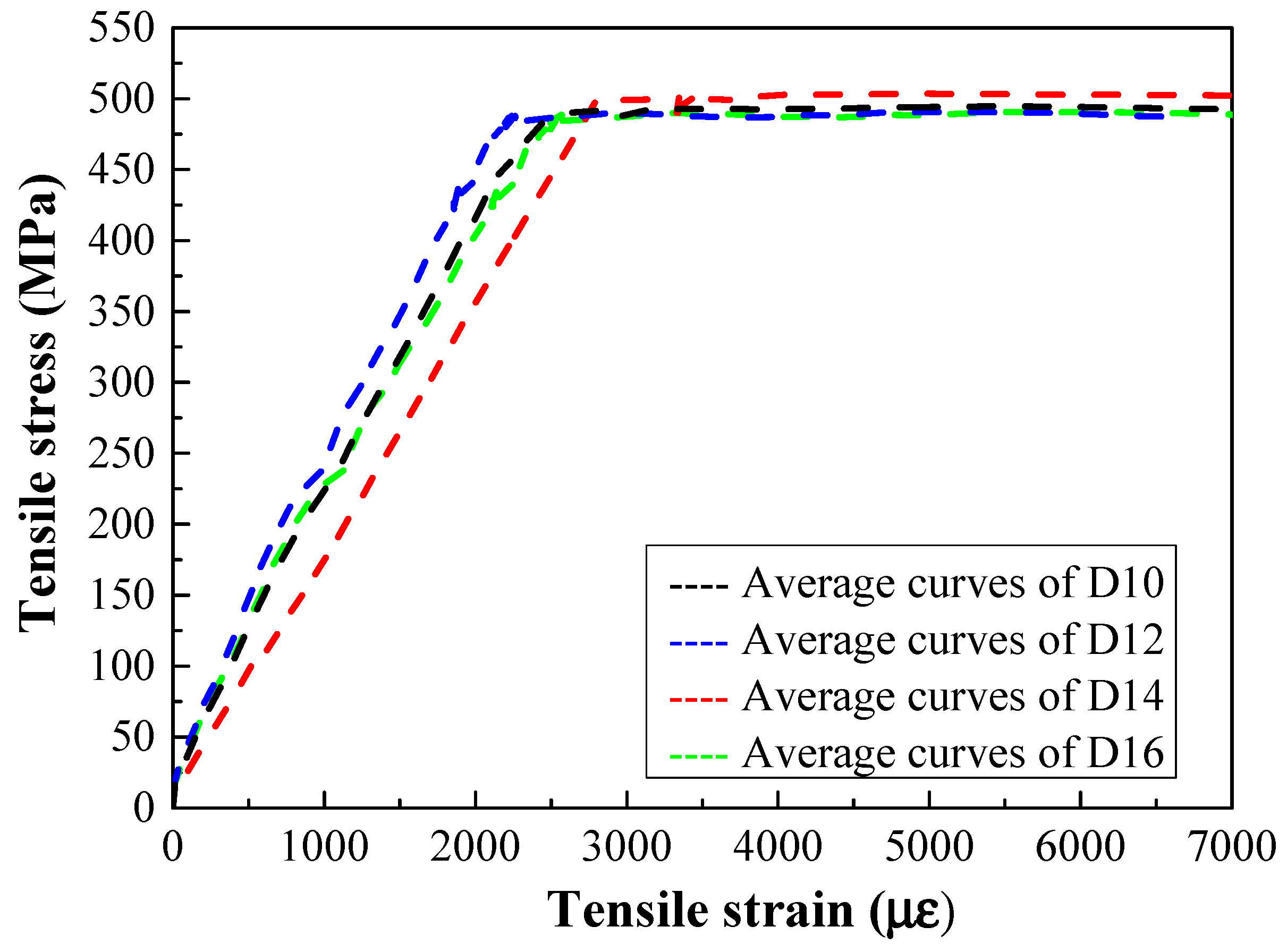
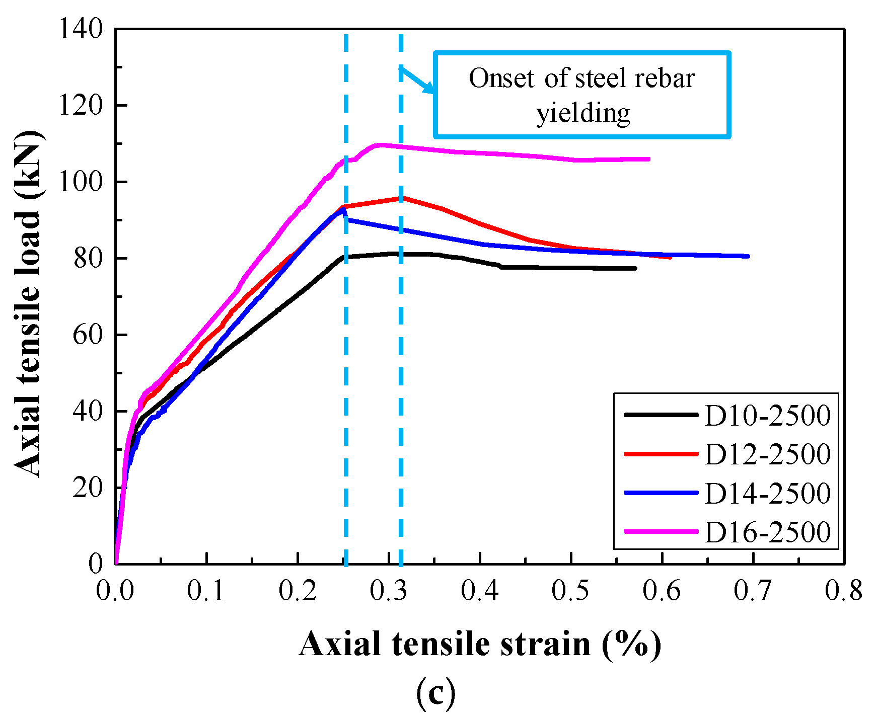
- In terms of load–strain response and envelope curves, the larger the diameter of embedded steel rebar, the smaller the maximum accumulative tensile strain under cyclic tension, which indicated that the larger the diameter of embedded steel rebar, the greater the contribution to the stiffness of the R-HSHUHPC specimens in the elastic–plastic stage.
- (3)
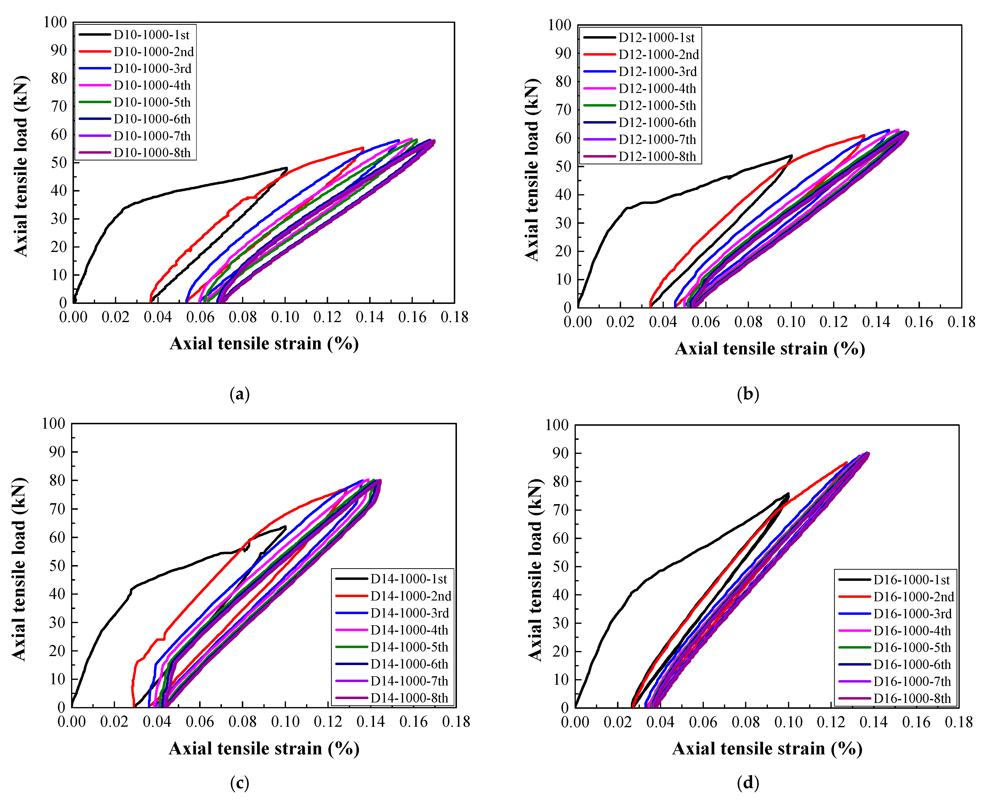
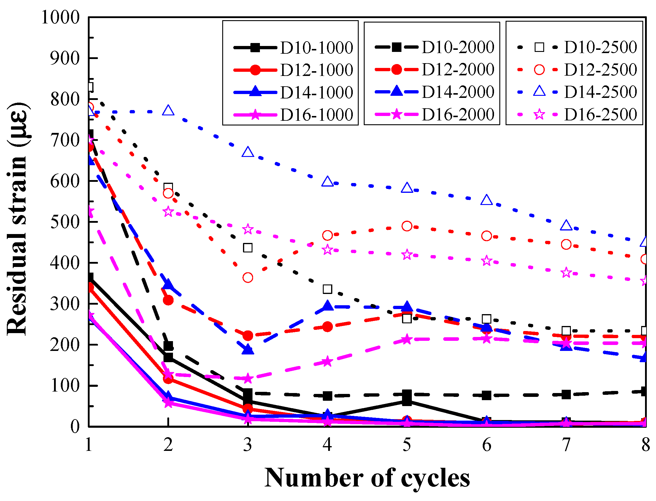
- For the target strain levels of 2000 με and 2500 με in each cycle, once the embedded steel rebar yielded and the crack width progressed beyond a certain threshold, fibers began to pull out, and the ability of the fibers to bridge the cracks began to decrease. Hence the residual strain and stiffness degradation rate in each cycle remained stable.
- (4)
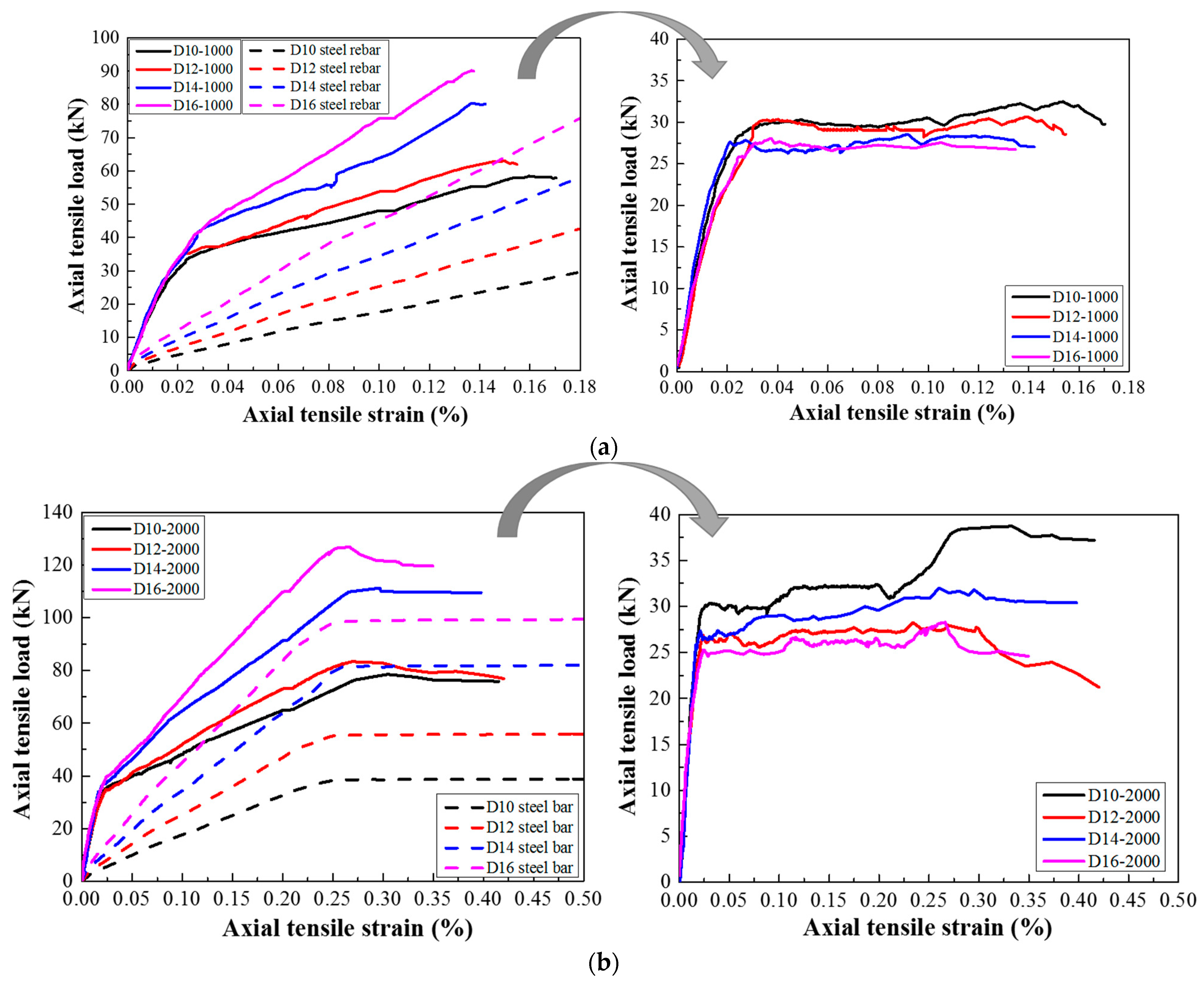
- According to the tension-stiffening response of steel-reinforced HSHUHPC members, the larger the embedded steel rebar, the lower the peak tensile strength of the HSHUHPC after deducting the steel rebar. This is most likely due to the fact that the larger diameter of the steel rebar results in a worse discontinuous distribution of the steel fiber, although the contact area between steel rebar and UHPC increases, and due to the presence of autogenous shrinkage, the bond interaction at the interface between steel rebar and UHPC is weaker.
- (5)
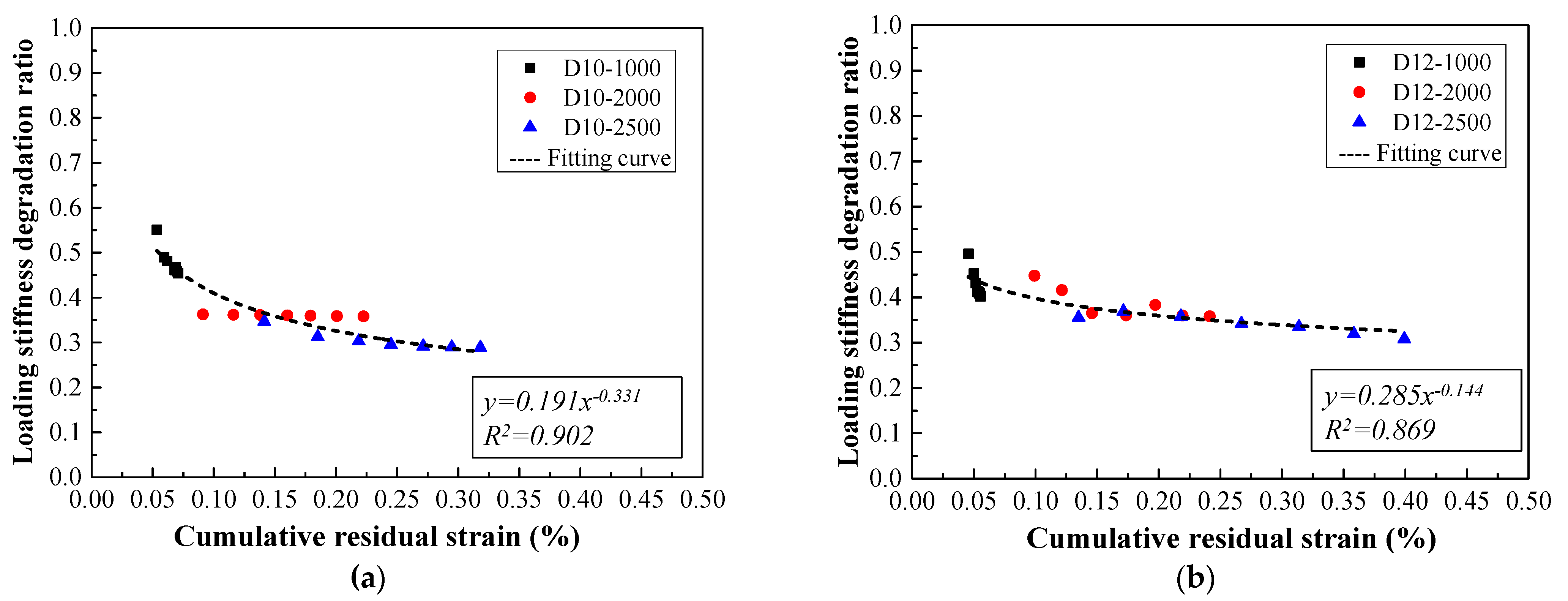
- The relationship model between the loading stiffness degradation ratio and the cumulative residual strain for steel-reinforced HSHUHPC members was proposed. The relationships can be employed to evaluate the stiffness of steel-reinforced HSHUHPC under cyclic tension to some extent.
Author Contributions
Funding
Institutional Review Board Statement
Informed Consent Statement
Data Availability Statement
Acknowledgments
Conflicts of Interest
References
- Graybeal, B.A. Material Property Characterization of Ultra-High-Performance Concrete; Report No. FHWA-HRT-06-103; FHWA: Washington, DC, USA, 2006. [Google Scholar]
- Yoo, D.-Y.; Kang, S.-T.; Yoon, Y.-S. Effect of fiber length and placement method on flexural behavior, tension-softening curve, and fiber distribution characteristics of UHPFRC. Constr. Build. Mater. 2014, 64, 67–81. [Google Scholar] [CrossRef]
- Abbas, M.L.N.S.; Saleem, M.A. Ultra-high performance concrete: Mechanical performance, durability, sustainability and im-plementation challenges. Int. J. Concr. Struct. Mater. 2016, 10, 271–295. [Google Scholar] [CrossRef] [Green Version]
- Brühwiler, E. Ultra-High Performance Fibre Reinforced Cement-Based Composites (UHPFRC) Construction Material Dimensioning und Application; Ecole Polytechnique Fe´de´rale de Lausanne (EPFL): Lausanne, Switzerland, 2016. [Google Scholar]
- Wang, J.-Y.; Guo, J.-Y. Damage investigation of ultra high performance concrete under direct tensile test using acoustic emission techniques. Cem. Concr. Compos. 2018, 88, 17–28. [Google Scholar] [CrossRef]
- Pyo, S.; Kim, H.-K.; Lee, B.Y. Effects of coarser fine aggregate on tensile properties of ultra high performance concrete. Cem. Concr. Compos. 2017, 84, 28–35. [Google Scholar] [CrossRef]
- Bian, C.; Wang, J.-Y. Mechanical and damage mechanisms of reinforced ultra high performance concrete under tensile loading. Constr. Build. Mater. 2019, 226, 259–279. [Google Scholar] [CrossRef]
- Hu, A.; Liang, X.; Shi, Q. Bond Characteristics between High-Strength Bars and Ultrahigh-Performance Concrete. J. Mater. Civ. Eng. 2020, 32, 04019323. [Google Scholar] [CrossRef]
- Kang, S.-T.; Kim, J.-K. The relation between fiber orientation and tensile behavior in an Ultra High Performance Fiber Reinforced Cementitious Composites (UHPFRCC). Cem. Concr. Res. 2011, 41, 1001–1014. [Google Scholar] [CrossRef]
- Zhang, Y.; Zhu, Y.; Yeseta, M.; Meng, D.; Shao, X.; Dang, Q.; Chen, G. Flexural behaviors and capacity prediction on damaged reinforcement concrete (RC) bridge deck strengthened by ultra-high performance concrete (UHPC) layer. Constr. Build. Mater. 2019, 215, 347–359. [Google Scholar] [CrossRef]
- Hung, C.-C.; Lee, H.-S.; Chan, S.N. Tension-stiffening effect in steel-reinforced UHPC composites: Constitutive model and effects of steel fibers, loading patterns, and rebar sizes. Compos. Part B Eng. 2019, 158, 269–278. [Google Scholar] [CrossRef]
- Wille, K.; El-Tawil, S.; Naaman, A. Properties of strain hardening ultra high performance fiber reinforced concrete (UHP-FRC) under direct tensile loading. Cem. Concr. Compos. 2014, 48, 53–66. [Google Scholar] [CrossRef]
- Moreno, D.M.; Trono, W.; Jen, G.; Ostertag, C.; Billington, S.L. Tension stiffening in reinforced high performance fiber reinforced cement-based com-posites. Cem. Concr. Compos. 2014, 50, 36–46. [Google Scholar] [CrossRef]
- Qiu, M.; Zhang, Y.; Qu, S.; Zhu, Y.; Shao, X. Effect of reinforcement ratio, fiber orientation, and fiber chemical treatment on the direct tension behavior of rebar-reinforced UHPC. Constr. Build. Mater. 2020, 256, 119311. [Google Scholar] [CrossRef]
- Redaelli, E.; Maffezzoli, B.P.; Redaelli, D. Initiation and propagation of reinforcement corrosion in ultra-high performance fibre reinforced concrete (UHPFRC). Metall. Ital. 2020, 4, 33–37. (In Italian) [Google Scholar]
- Hung, C.-C.; Chueh, C.-Y. Cyclic behavior of UHPFRC flexural members reinforced with high-strength steel rebar. Eng. Struct. 2016, 122, 108–120. [Google Scholar] [CrossRef]
- Hung, C.-C.; Yen, W.-M.; Yu, K.-H. Vulnerability and improvement of reinforced ECC flexural members under displacement reversals: Experimental investigation and computational analysis. Constr. Build. Mater. 2016, 107, 287–298. [Google Scholar] [CrossRef]
- Roy, M.; Hollmann, C.; Wille, K. Influence of Fiber Volume Fraction and Fiber Orientation on the Uniaxial Tensile Behavior of Rebar-Reinforced Ultra-High Performance Concrete. Fibers 2019, 7, 67. [Google Scholar] [CrossRef] [Green Version]
- Makita, T.; Brühwiler, E. Tensile fatigue behaviour of Ultra-High Performance Fibre Reinforced Concrete combined with steel rebars (R-UHPFRC). Int. J. Fatigue 2014, 59, 145–152. [Google Scholar] [CrossRef]
- Makita, T.; Bruehwiler, E. Damage models for UHPFRC and R-UHPFRC tensile fatigue behaviour. Eng. Struct. 2015, 90, 61–70. [Google Scholar] [CrossRef]
- Standardization Administration of the People’s Republic of China (SAC). GB/T 31387-2015 Reactive Power Concrete; Standards Press of China: Beijing, China, 2015. [Google Scholar]
- Guo, J.-Y.; Wang, J.-Y.; Bian, C. Cyclic tensile behavior of high strain hardening UHPC analyzed by acoustic emission techniques. Constr. Build. Mater. 2021, 267, 121797. [Google Scholar] [CrossRef]


| Specimen | Diameter of Embedded Rebar (mm) | Loading Pattern | Target Strain (με) |
|---|---|---|---|
| R-HSHUHPC-D10 | 10 | monotonic tension | 25,000 |
| R-HSHUHPC-D12 | 12 | monotonic tension | 25,000 |
| R-HSHUHPC-D14 | 14 | monotonic tension | 25,000 |
| R-HSHUHPC-D16 | 16 | monotonic tension | 25,000 |
| D10-1000 | 10 | cyclic tension | 1000 |
| D10-2000 | 10 | cyclic tension | 2000 |
| D10-2500 | 10 | cyclic tension | 2500 |
| D12-1000 | 12 | cyclic tension | 1000 |
| D12-2000 | 12 | cyclic tension | 2000 |
| D12-2500 | 12 | cyclic tension | 2500 |
| D14-1000 | 14 | cyclic tension | 1000 |
| D14-2000 | 14 | cyclic tension | 2000 |
| D14-2500 | 14 | cyclic tension | 2500 |
| D16-1000 | 16 | cyclic tension | 1000 |
| D16-2000 | 16 | cyclic tension | 2000 |
| D16-2500 | 16 | cyclic tension | 2500 |
| Cement | Silica Fume | Fine Filler | Fine Aggregate | Water | Superplasticizer |
|---|---|---|---|---|---|
| 1 | 0.3 | 0.3 | 1.34 | 0.2 | 0.005 |
| Fiber Type | (MPa) | (GPa) | l (mm) | d (μm) | μ | Density (kg·m−3) |
|---|---|---|---|---|---|---|
| steel fiber | 2500 | 200 | 16 | 200 | 80 | 7850 |
Publisher’s Note: MDPI stays neutral with regard to jurisdictional claims in published maps and institutional affiliations. |
© 2021 by the authors. Licensee MDPI, Basel, Switzerland. This article is an open access article distributed under the terms and conditions of the Creative Commons Attribution (CC BY) license (https://creativecommons.org/licenses/by/4.0/).
Share and Cite
Gu, J.-B.; Wang, J.-Y.; Guo, Y.-Q. Cyclic Behavior of Reinforced High Strain-Hardening UHPC under Axial Tension. Materials 2021, 14, 3602. https://doi.org/10.3390/ma14133602
Gu J-B, Wang J-Y, Guo Y-Q. Cyclic Behavior of Reinforced High Strain-Hardening UHPC under Axial Tension. Materials. 2021; 14(13):3602. https://doi.org/10.3390/ma14133602
Chicago/Turabian StyleGu, Jin-Ben, Jun-Yan Wang, and Yi-Qing Guo. 2021. "Cyclic Behavior of Reinforced High Strain-Hardening UHPC under Axial Tension" Materials 14, no. 13: 3602. https://doi.org/10.3390/ma14133602
APA StyleGu, J.-B., Wang, J.-Y., & Guo, Y.-Q. (2021). Cyclic Behavior of Reinforced High Strain-Hardening UHPC under Axial Tension. Materials, 14(13), 3602. https://doi.org/10.3390/ma14133602