
Balancing Strength and Ductility in Al Matrix Composites Reinforced by Few-Layered MoS2 through In-Situ Formation of Interfacial Al12Mo

 and
and 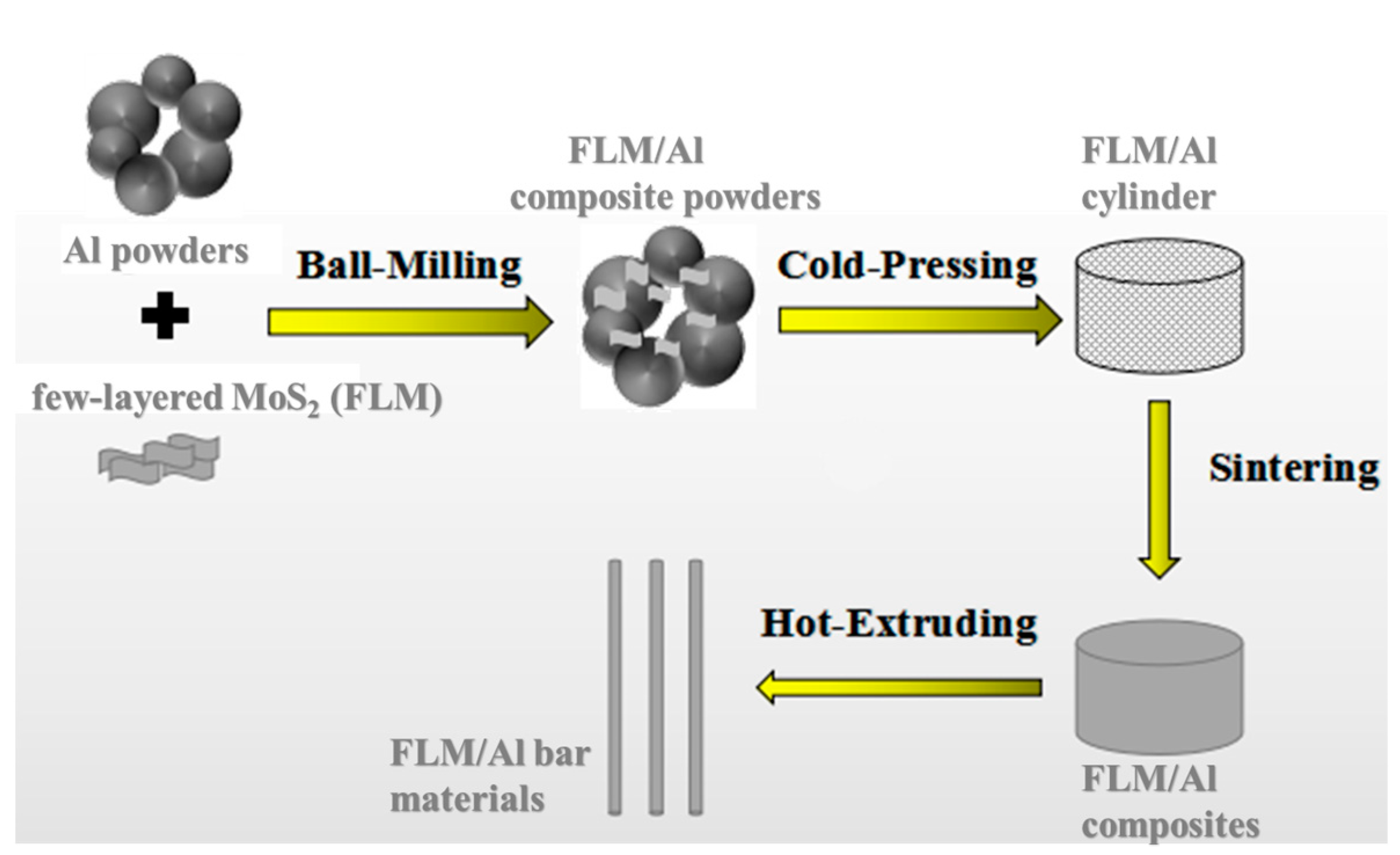
Abstract
:1. Introduction
2. Materials and Methods
2.1. Materials and Fabrication of FLM/Al Composites
2.2. Characterization
3. Results
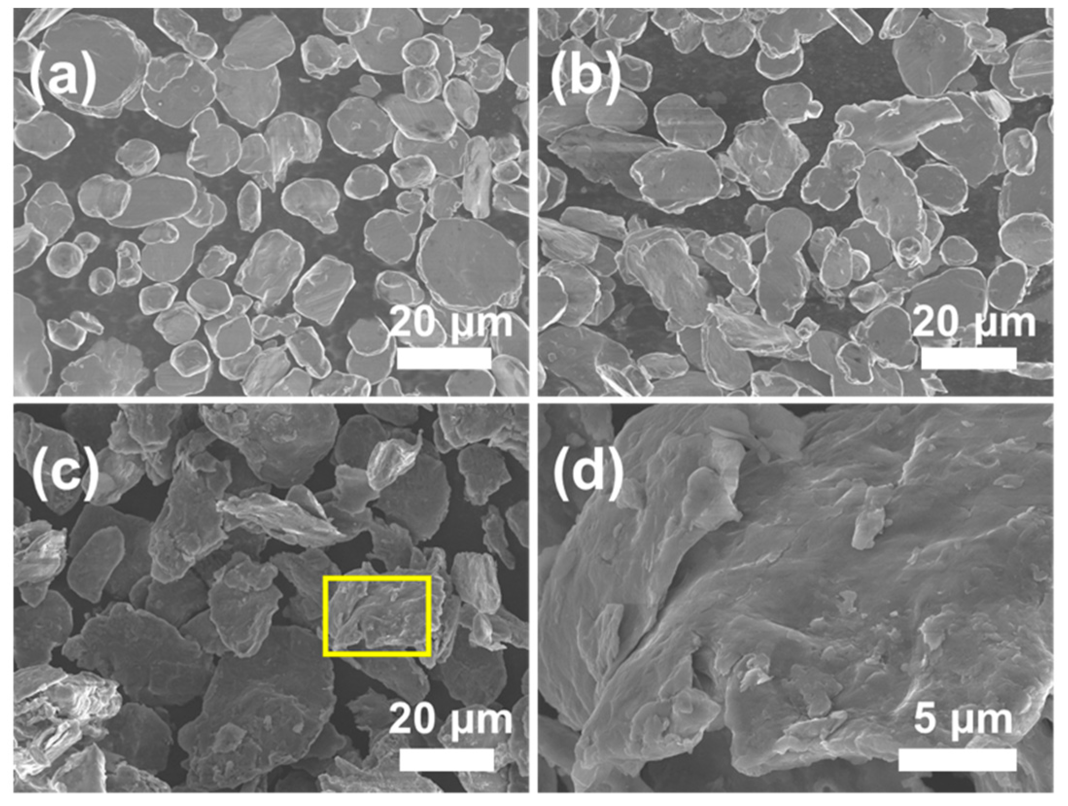
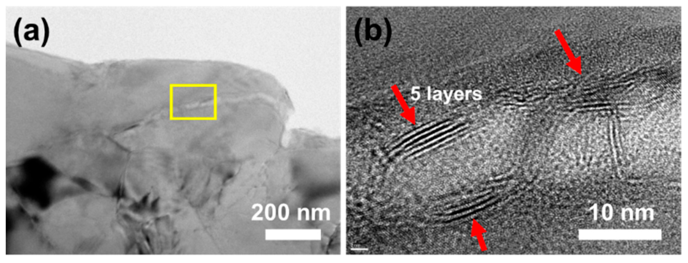
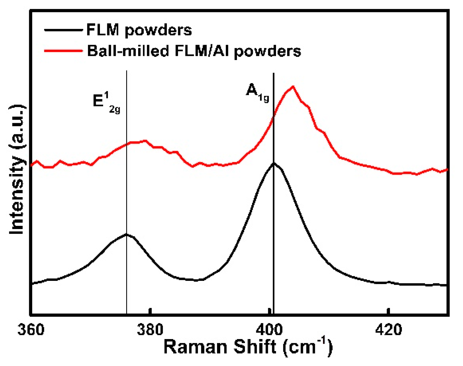
3.1. Microstructure of Composite Powders
3.2. Mechanical Properties and Microstructure of Bulk Composites
3.2.1. Mechanical Properties of Bulk Composites
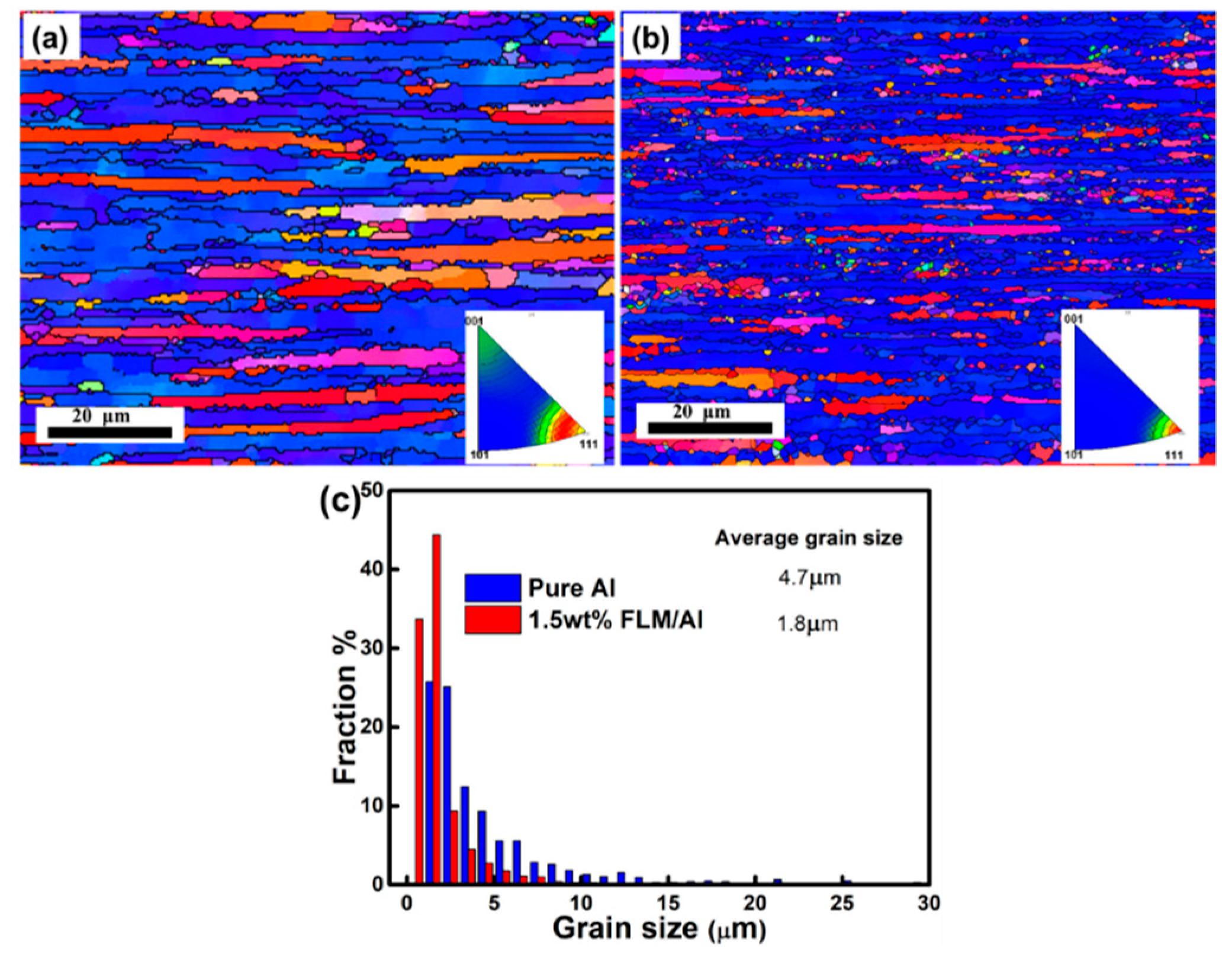
3.2.2. Microstructure of Bulk Composites
3.3. Enhancement by Interfacial Reaction Process
3.4. Strengthening Mechanisms Contribution Calculation
- (i)
- Grain refinement
- (ii)
- Dislocation strengthening
- (iii)
- Load transfer
4. Conclusions
- (1)
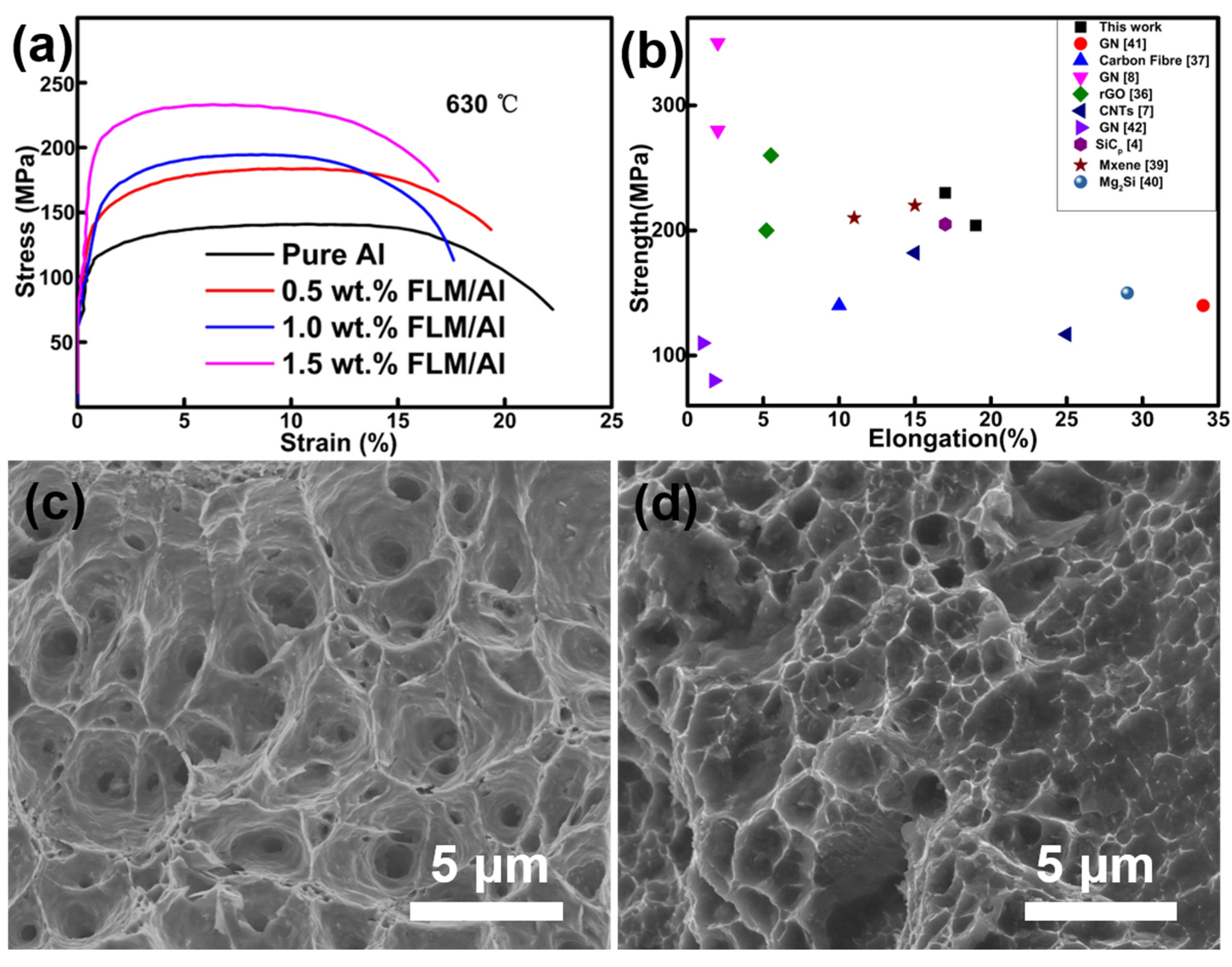
- When the content of FLM in the composites reached 1.5 wt.%, the composites exhibited the highest ultimate tensile strength and yield strength of 234 and 210 MPa, respectively.
- (2)
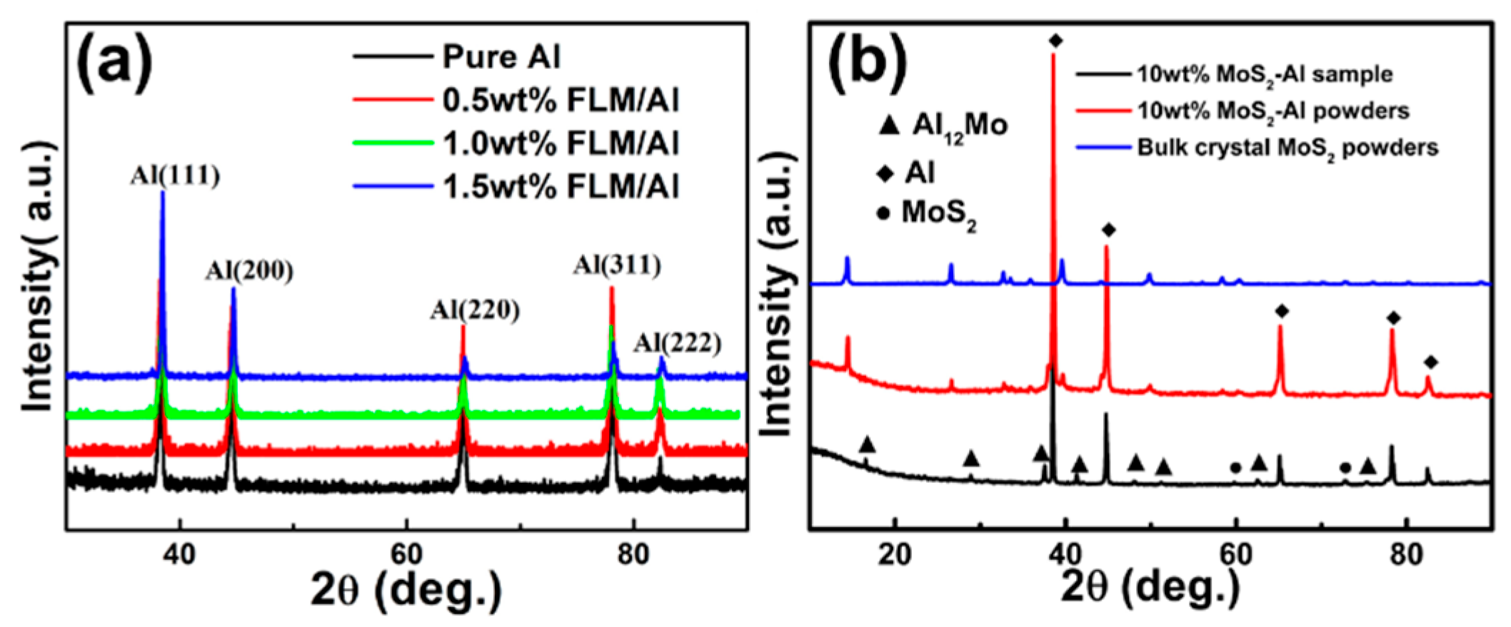
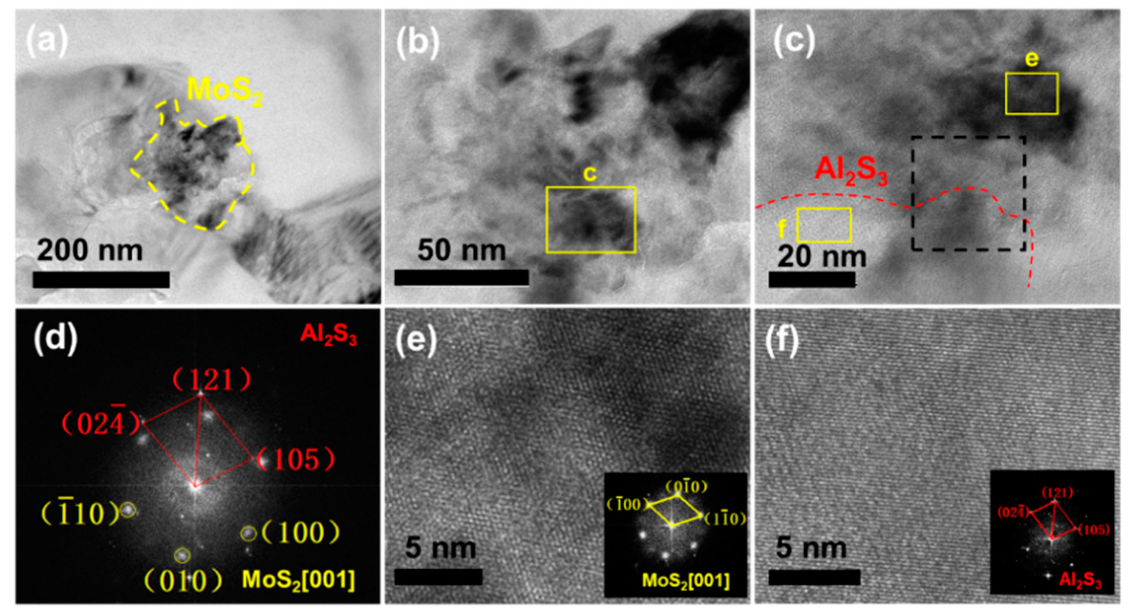
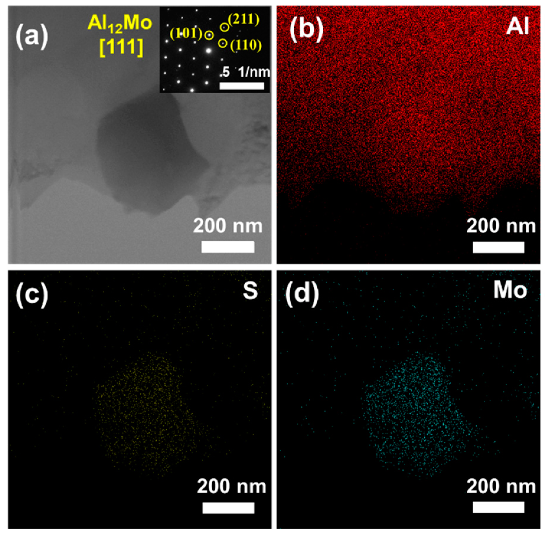
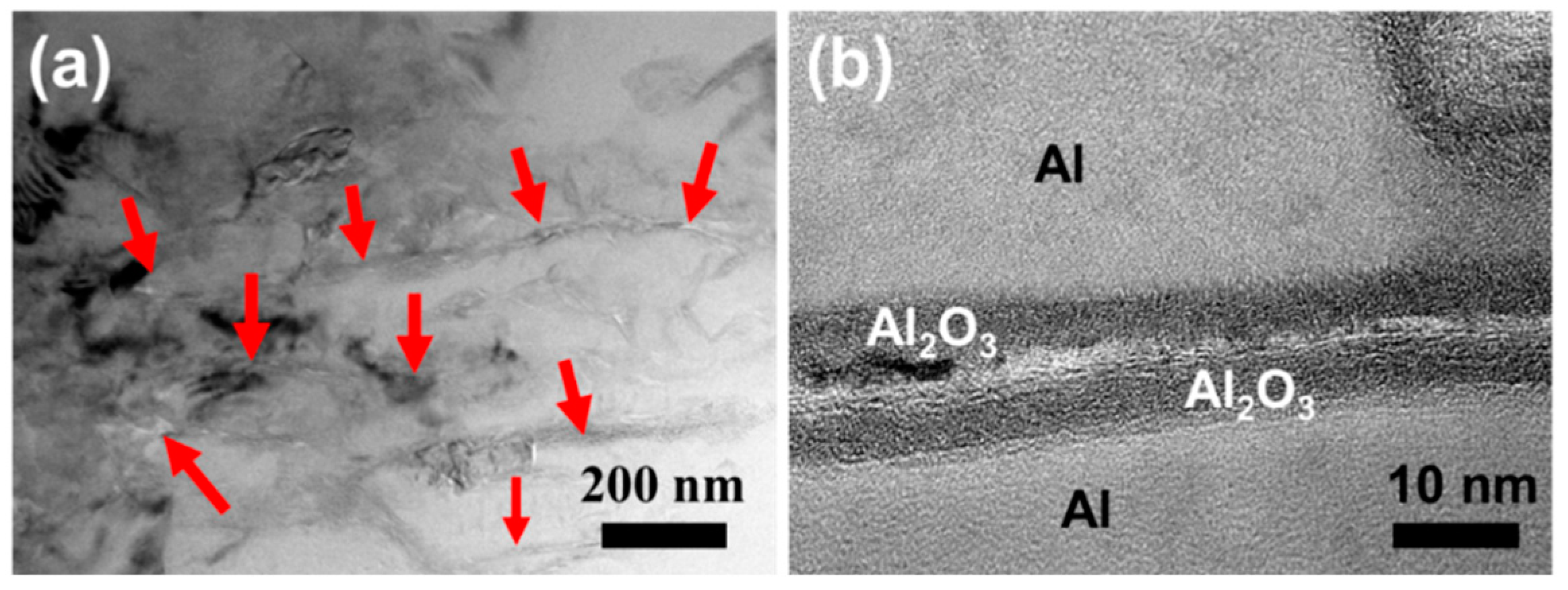
- It was found that MoS2 could react with Al to form Al2S3 and Al12Mo at 630 °C. The interface reaction generates strong chemical bonding between the matrix and reinforcement. The in-situ-formed Al12Mo played an important role in enhancement of Al matrix composites.
- (3)
- There are three kinds of strengthening models: (i) grain refinement, (ii) dislocation strengthening, and (iii) load transfer. Load transfer is the dominant mechanism responsible for the improvement of strength based on the calculation of contribution by each mechanism.
Supplementary Materials
Author Contributions
Funding
Institutional Review Board Statement
Informed Consent Statement
Data Availability Statement
Conflicts of Interest
References
- Dursun, T.; Soutis, C. Recent developments in advanced aircraft aluminium alloys. Mater. Des. 2014, 56, 862. [Google Scholar] [CrossRef]
- Prasad, S.V.; Asthana, R. Aluminum metal–matrix composites for automotive applications: Tribological considerations. Tribol. Lett. 2004, 17, 13. [Google Scholar] [CrossRef]
- Min, Z.; Feng, G.; Xiao-yang, L. Research Progress of Composites for Electronic Packaging Materials. Mater. Rev. 2013, 27, 3. [Google Scholar]
- Kollo, L.; Bradbury, C.R.; Veinthal, R.; Jäggi, C.; Carreño-Morelli, E.; Leparoux, M. Nano-silicon carbide reinforced aluminium produced by high-energy milling and hot consolidation. Mater. Sci. Eng. A 2011, 528, 6606–6615. [Google Scholar] [CrossRef]
- Guo, H.; Zhang, Z.; Zhang, Y.; Cui, Y.; Sun, L.; Chen, D. Improving the mechanical properties of B4C/Al composites by solid-state interfacial reaction. J. Alloys Compd. 2020, 829, 154521. [Google Scholar] [CrossRef]
- Li, G.; Xu, T.; Wang, H.; Xie, M.; Liu, M.; Zhang, D.; Zhao, Y.; Chen, G.; Kai, X. Microstructure and performance of nanometer γ-Al2O3p/Al composite fabricated in Al-Co3O4 components. Mater. Lett. 2019, 253, 346–348. [Google Scholar] [CrossRef]
- Xu, R.; Tan, Z.; Xiong, D.; Fan, G.; Guo, Q.; Zhang, J.; Su, Y.; Li, Z.; Zhang, D. Balanced strength and ductility in CNT/Al composites achieved by flake powder metallurgy via shift-speed ball milling. Compos. Part A Appl. Sci. Manuf. 2017, 96, 57–66. [Google Scholar] [CrossRef]
- Huang, Y.; Wan, D.Q.; Luo, D.; Henrique, P.; Pereira, R.; Lewandowska, M.; Yao, J.; Hayden, B.E.; Langdon, T.G. The fabrication of graphene-reinforced Al-based nanocomposites using high-pressure torsion. Acta Mater. 2019, 164, 499. [Google Scholar] [CrossRef]
- Han, T.; Li, J.; Zhao, N.; He, C. Microstructure and properties of copper coated graphene nanoplates reinforced Al matrix composites developed by low temperature ball milling. Carbon 2020, 159, 311–323. [Google Scholar] [CrossRef]
- Zhang, Z.W.; Liu, Z.Y.; Xiao, B.L.; Ni, D.R.; Ma, Z.Y. High efficiency dispersal and strengthening of graphene reinforced aluminum alloy composites fabricated by powder metallurgy combined with friction stir processing. Carbon 2018, 135, 215. [Google Scholar] [CrossRef]
- Zhu, Y.W.; Murali, S.; Cai, W.W.; Li, X.S.; Suk, J.W.; Potts, J.R.; Ruoff, R.S. Graphene and graphene oxide: Synthesis, properties, and applications. Adv. Mater. 2010, 22, 3906. [Google Scholar] [CrossRef]
- Wang, J.Y.; Fan, G.L.; Li, Z.Q.; Zhang, D. Reinforcement with graphene nanosheets in aluminum matrix composites Scr. Mater. 2012, 66, 4. [Google Scholar]
- Shin, S.E.; Choi, H.J.; Shin, J.H.; Bae, D.H. Strengthening behavior of few-layered graphene/aluminum composites. Carbon 2015, 82, 143–151. [Google Scholar] [CrossRef]
- Zhang, X.; Lai, Z.C.; Tan, C.L.; Zhang, H. Solution-Processed Two-Dimensional MoS2 Nanosheets: Preparation, Hybridization, and Applications. Angew. Chem. Int. Ed. 2016, 55, 8816–8838. [Google Scholar] [CrossRef]
- Huang, X.; Zeng, Z.; Zhang, H. Metal dichalcogenide nanosheets: Preparation, properties and applications. Chem. Soc. Rev. 2013, 42, 1934–1946. [Google Scholar] [CrossRef] [PubMed]
- Choi, W.; Choudhary, N.; Han, G.H.; Park, J.; Akinwande, D.; Lee, Y.H. Recent development of two-dimensional transition metal dichalcogenides and their applications. Mater. Today 2017, 20, 116–130. [Google Scholar] [CrossRef]
- Castellanos-Gomez, A.; Poot, M.; Steele, G.A.; Van Der Zant, H.S.; Agraït, N.; Rubio-Bollinger, G. Elastic properties of freely suspended MoS2 nanosheets. Adv. Mater. 2012, 24, 772–775. [Google Scholar] [CrossRef] [PubMed] [Green Version]
- Bertolazzi, S.; Brivio, J.; Kis, A. Stretching and Breaking of Ultrathin MoS2. Adv. Mater. 2012, 24, 7. [Google Scholar] [CrossRef] [PubMed]
- Li, N.; Zhu, L.; Zhang, Y.; Huan, Y. Controllable syntheses and potential applications of two-dimensional metallic transition metal dichalcogenides. Chin. Sci. Bull. 2020, 66, 34–52. [Google Scholar] [CrossRef]
- Xu, L.; Zhang, Y.; Feng, L.; Li, X.; An, Q. A facile preparation method for MoS2 nanosheets and their well-controllable interfacial assembly with PEDOT: PSS for effective electrochemical hydrogen evolution reactions. J. Mater. Sci. 2021, 56, 7008–7021. [Google Scholar] [CrossRef]
- Presolski, S.; Wang, L.; Loo, A.H.; Ambrosi, A.; Lazar, P.; Ranc, V.; Otyepka, M.; Zboril, R.; Tomanec, O.; Ugolotti, J.; et al. Functional Nanosheet Synthons by Covalent Modification of Transition-Metal Dichalcogenides. Chem. Mater. 2017, 29, 2066–2073. [Google Scholar] [CrossRef]
- Peng, H.; Wang, D.; Fu, S. Tannic acid-assisted green exfoliation and functionalization of MoS2 nanosheets: Significantly improve the mechanical and flame-retardant properties of polyacrylonitrile composite fibers. Chem. Eng. J. 2020, 384, 123288. [Google Scholar] [CrossRef]
- Zhang, J.; Lei, W.; Schutz, J.; Liu, D.; Tang, B.; Wang, C.H.; Wang, X. Improving the gas barrier, mechanical and thermal properties of poly(vinyl alcohol) with molybdenum disulfide nanosheets. Polym. Sci. Part B Polym. Phys. 2019, 57, 406–414. [Google Scholar] [CrossRef]
- Huang, S.-J.; Peng, W.-Y.; Visic, B.; Zak, A. Al alloy metal matrix composites reinforced by WS2 inorganic nanomaterials. Mater. Sci. Eng. A 2018, 709, 290–300. [Google Scholar] [CrossRef]
- Kato, H.; Takama, M.; Iwai, Y.; Washida, K.; Sasaki, Y. Wear and mechanical properties of sintered copper–tin composites containing graphite or molybdenum disulfide. Wear 2003, 255, 573–578. [Google Scholar] [CrossRef]
- Xiao, J.-K.; Zhang, W.; Liu, L.-M.; Zhang, L.; Zhang, C. Tribological behavior of copper-molybdenum disulfide composites. Wear 2017, 384, 61–71. [Google Scholar] [CrossRef]
- Furlan, K.P.; Prates, P.B.; Andrea dos Santos, T.; Gouvêa Dias, M.V.; Ferreira, H.T.; Rodrigues Neto, J.B.; Klein, A.N. Influence of alloying elements on the sintering thermodynamics, microstructure and properties of Fe–MoS2 composites. J. Alloys Compd. 2015, 652, 450–458. [Google Scholar] [CrossRef]
- Kumar, V.; Gautam, R.K.; Tyagi, R. Tribological behavior of Al-based self-lubricating composites. Compos. Interfaces 2016, 23, 481–492. [Google Scholar] [CrossRef]
- Wozniak, J.; Kostecki, M.; Cygan, T.; Buczek, M.; Olszyna, A. Self-lubricating aluminium matrix composites reinforced with 2D crystals. Compos. B Eng. 2017, 111, 1–9. [Google Scholar] [CrossRef]
- Liu, S.; Wang, Y.; Muthuramalingam, T.; Anbuchezhiyan, G. Effect of B4C and MoS2 reinforcement on micro structure and wear properties of aluminum hybrid composite for automotive applications. Compos. B Eng. 2019, 176. [Google Scholar] [CrossRef]
- Rouhi, M.; Moazami-Goudarzi, M.; Ardestani, M. Comparison of effect of SiC and MoS2 on wear behavior of Al matrix composites. Trans. Nonferrous Met. Soc. China 2019, 29, 1169–1183. [Google Scholar] [CrossRef]
- Vinoth, K.S.; Subramanian, R.; Dharmalingam, S. Mechanical and tribological characteristics of stir-cast Al-Si10Mg and self-lubricating Al-Si10Mg/MoS2 composites. Mater. Technol. 2012, 46, 497–501. [Google Scholar]
- Rebba, B.; Ramanaiah, N. Evaluation of Mechanical Properties of Aluminium Alloy (Al-2024) Reinforced with Molybdenum Disulphide (MoS2) Metal Matrix Composites. Procedia Mater Sci. 2014, 6, 1161–1169. [Google Scholar] [CrossRef] [Green Version]
- Ambrosi, A.; Chia, X.; Sofer, Z.; Pumera, M. Enhancement of electrochemical and catalytic properties of MoS2 through ball-milling. Electrochem. Commun. 2015, 54, 36–40. [Google Scholar] [CrossRef]
- Takacs, L.; Balaz, P.; Torosyan, A.R. Ball milling-induced reduction of MoS2 with al. J. Mater. Sci. 2006, 41, 7033–7039. [Google Scholar] [CrossRef]
- Li, Z.; Guo, Q.; Li, Z.; Fan, G.; Xiong, D.B.; Su, Y.; Zhang, J.; Zhang, D. Enhanced Mechanical Properties of Graphene (Reduced Graphene Oxide)/Aluminum Composites with a Bioinspired Nanolaminated Structure. Nano Lett. 2015, 15, 8077–8083. [Google Scholar] [CrossRef] [PubMed]
- Lu, Z.Z.; Zu, Y.F.; Sha, J.J.; Xian, Y.Q.; Zhang, W.; Cut, D.; Yan, C.L. Fabrication and Mechanical Properties of Carbon Fiber-Reinforced Aluminum Matrix Composites with Cu Interphase. Acta Metall. Sin. 2019, 55, 317–324. [Google Scholar]
- Li, M.Q.; Wang, S.K.; Wang, Q.H.; Zhao, Z.H.; Duan, C.Y.; Zhao, D.; Zhang, L.Z.; Wang, Y. Microstructure and mechanical properties of MoAlB particles reinforced Al matrix composites by interface modification with in situ formed Al12Mo. J. Alloys Compd. 2020, 823, 153813. [Google Scholar] [CrossRef]
- Zhou, W.; Zhou, Z.; Fan, Y.; Nomura, N. Significant strengthening effect in few-layered MXene-reinforced Al matrix composites. Mater. Res. Lett. 2020, 9, 148–154. [Google Scholar] [CrossRef]
- Chegini, M.; Shaeri, M.H.; Taghiabadi, R.; Cheginy, S. Effect of equal channel angular pressing on microstructure and mechanical properties of thermally-homogenized Al–Mg2Si composites. Mater. Chem. Phys. 2021, 259, 124200. [Google Scholar] [CrossRef]
- Bhadauria, A.; Singh, L.K.; Laha, T. Effect of physio-chemically functionalized graphene nanoplatelet reinforcement on tensile properties of aluminum nanocomposite synthesized via spark plasma sintering. J. Alloys Compd. 2018, 748, 783–793. [Google Scholar] [CrossRef]
- Bisht, A.; Kumar, V.; Li, L.H.; Chen, Y.; Agarwal, A.; Lahiri, D. Effect of warm rolling and annealing on the mechanical properties of aluminum composite reinforced with boron nitride nanotubes. Mater. Sci. Eng. A 2018, 710, 366–373. [Google Scholar] [CrossRef]
- Zhang, W.L.; Gu, M.Y.; Wang, D.Z.; Yao, Z.K. Rolling and annealing textures of a SiCw/Al composite. Mater. Lett. 2004, 58, 3414–3418. [Google Scholar] [CrossRef]
- Tang, R.Z.; Tian, R.Z. (Eds.) Binary Alloy Phase Diagrams and Crystal Structure of Intermediate Phase; Central South University Press: Changsha, China, 2009. [Google Scholar]
- Straumal, B.B.; Mazilkin, A.A.; Baretzky, B. Grain boundary complexions and pseudopartial wetting. Curr. Opin. Sol. State Mater. Sci. 2016, 20, 247–256. [Google Scholar] [CrossRef]
- Chang, L.-S.; Rabkin, E.; Straumal, B.; Lejeek, P.; Hofinan, S.; Gust, W. Temperature dependence og the grain boundary segregation of Bi in Cu polycrystals. J. Phase Equlibria 1997, 18, 128–135. [Google Scholar] [CrossRef]
- Chang, L.-S.; Rabkin, E.; Straumal, B.; Gust, W.; Sommer, F. The Solidus Line of the Cu-Bi Phase Diagram. Scr. Mater. 1997, 37, 729–735. [Google Scholar] [CrossRef]
- Tao, X.; Liu, Y.; Wang, R.; Ouyang, Y.; Du, Y.; He, Y. First-principles investigations of elastic, electronic and thermodynamic properties of Al12X (X = Mo, W and Re). Intermetallics 2012, 24, 15–21. [Google Scholar] [CrossRef]
- Bian, Y.; Gao, T.; Li, Z.; Sun, Q.; Ma, X.; Liu, X. In–situ synthesis of an Al composite reinforced with multi–scale Al12Mo, (Al, Zr, Si) and Al2O3 particles through a multi–stage reaction. Mater. Sci. Eng. A 2019, 762, 138069. [Google Scholar] [CrossRef]
- Li, L.; Wang, L.P.; Wang, X.F. Reaction Mechanism and Synthesis of Ni3Al–MoS2 Matrix Self-Lubricating Composites Using Ni, Al, and MoS2 Powders. J. Inorg. Organomet Polym. 2017, 28, 223. [Google Scholar] [CrossRef]
- Zhou, W.; Dong, M.; Zhou, Z.; Sun, X.; Kikuchi, K.; Nomura, N.; Kawasaki, A. In situ formation of uniformly dispersed Al4C3 nanorods during additive manufacturing of graphene oxide/Al mixed powders. Carbon 2019, 141, 67–75. [Google Scholar] [CrossRef]
- De Jong, M.; Chen, W.; Angsten, T.; Jain, A.; Notestine, R.; Gamst, A.; Sluiter, M.; Krishna Ande, C.; van der Zwaag, S.; Plata, J.J.; et al. Charting the complete elastic properties of inorganic crystalline compounds. Sci. Data 2015, 2, 150009. [Google Scholar] [CrossRef] [Green Version]
- George, R.; Kashyap, K.T.; Rahul, R.; Yamdagni, S. Strengthening in carbon nanotube/aluminium (CNT/Al) composites. Scr. Mater. 2005, 53, 1159–1163. [Google Scholar] [CrossRef]
- Shan, Y.; Pu, B.; Liu, E.; Shi, C.; He, C.; Zhao, N. In-situ synthesis of CNTs@Al2O3 wrapped structure in aluminum matrix composites with balanced strength and toughness. Mater. Sci. Eng. A 2020, 797, 140058. [Google Scholar] [CrossRef]
- Rong, X.; Zhang, X.; Zhao, D.; He, C.; Shi, C.; Liu, E.; Zhao, N. In-situ Al2O3-Al interface contribution towards the strength-ductility synergy of Al-CuO composite fabricated by solid-state reactive sintering. Scr. Mater. 2021, 198, 113825. [Google Scholar] [CrossRef]
- Jiang, Y.; Tan, Z.; Fan, G.; Wang, L.; Xiong, D.; Guo, Q.; Su, Y.; Li, Z.; Zhang, D. Reaction-free interface promoting strength-ductility balance in graphene nanosheet/Al composites. Carbon 2020, 158, 449–455. [Google Scholar] [CrossRef]
- Chu, K.; Wang, F.; Li, Y.-b.; Wang, X.-h.; Huang, D.-j.; Zhang, H. Interface structure and strengthening behavior of graphene/CuCr composites. Carbon 2018, 133, 127–139. [Google Scholar] [CrossRef]
- Shin, S.E.; Bae, D.H. Deformation behavior of aluminum alloy matrix composites reinforced with few-layer graphene. Compos. Part A Appl. Sci. Manuf. 2015, 78, 42–47. [Google Scholar] [CrossRef]
- Rong, X.; Zhao, D.; He, C.; Shi, C.; Liu, E.; Zhao, N. Revealing the strengthening and toughening mechanisms of Al-CuO composite fabricated via in-situ solid-state reaction. Acta Mater. 2021, 204, 116524. [Google Scholar] [CrossRef]


Publisher’s Note: MDPI stays neutral with regard to jurisdictional claims in published maps and institutional affiliations. |
© 2021 by the authors. Licensee MDPI, Basel, Switzerland. This article is an open access article distributed under the terms and conditions of the Creative Commons Attribution (CC BY) license (https://creativecommons.org/licenses/by/4.0/).
Share and Cite
Fan, L.; Yang, L.; Zhao, D.; Ma, L.; He, C.; He, F.; Shi, C.; Sha, J.; Zhao, N. Balancing Strength and Ductility in Al Matrix Composites Reinforced by Few-Layered MoS2 through In-Situ Formation of Interfacial Al12Mo. Materials 2021, 14, 3561. https://doi.org/10.3390/ma14133561
Fan L, Yang L, Zhao D, Ma L, He C, He F, Shi C, Sha J, Zhao N. Balancing Strength and Ductility in Al Matrix Composites Reinforced by Few-Layered MoS2 through In-Situ Formation of Interfacial Al12Mo. Materials. 2021; 14(13):3561. https://doi.org/10.3390/ma14133561
Chicago/Turabian StyleFan, Lewen, Lizhuang Yang, Dongdong Zhao, Liying Ma, Chunnian He, Fang He, Chunsheng Shi, Junwei Sha, and Naiqin Zhao. 2021. "Balancing Strength and Ductility in Al Matrix Composites Reinforced by Few-Layered MoS2 through In-Situ Formation of Interfacial Al12Mo" Materials 14, no. 13: 3561. https://doi.org/10.3390/ma14133561
APA StyleFan, L., Yang, L., Zhao, D., Ma, L., He, C., He, F., Shi, C., Sha, J., & Zhao, N. (2021). Balancing Strength and Ductility in Al Matrix Composites Reinforced by Few-Layered MoS2 through In-Situ Formation of Interfacial Al12Mo. Materials, 14(13), 3561. https://doi.org/10.3390/ma14133561