
Manufacturing Elements with Small Cross-Sections of 17-4 PH Steel (1.4542) with the Application of the DMLS Additive Manufacturing Method

 ,
,  , , , and
Abstract
:1. Introduction
2. Materials and Methods
2.1. Materials
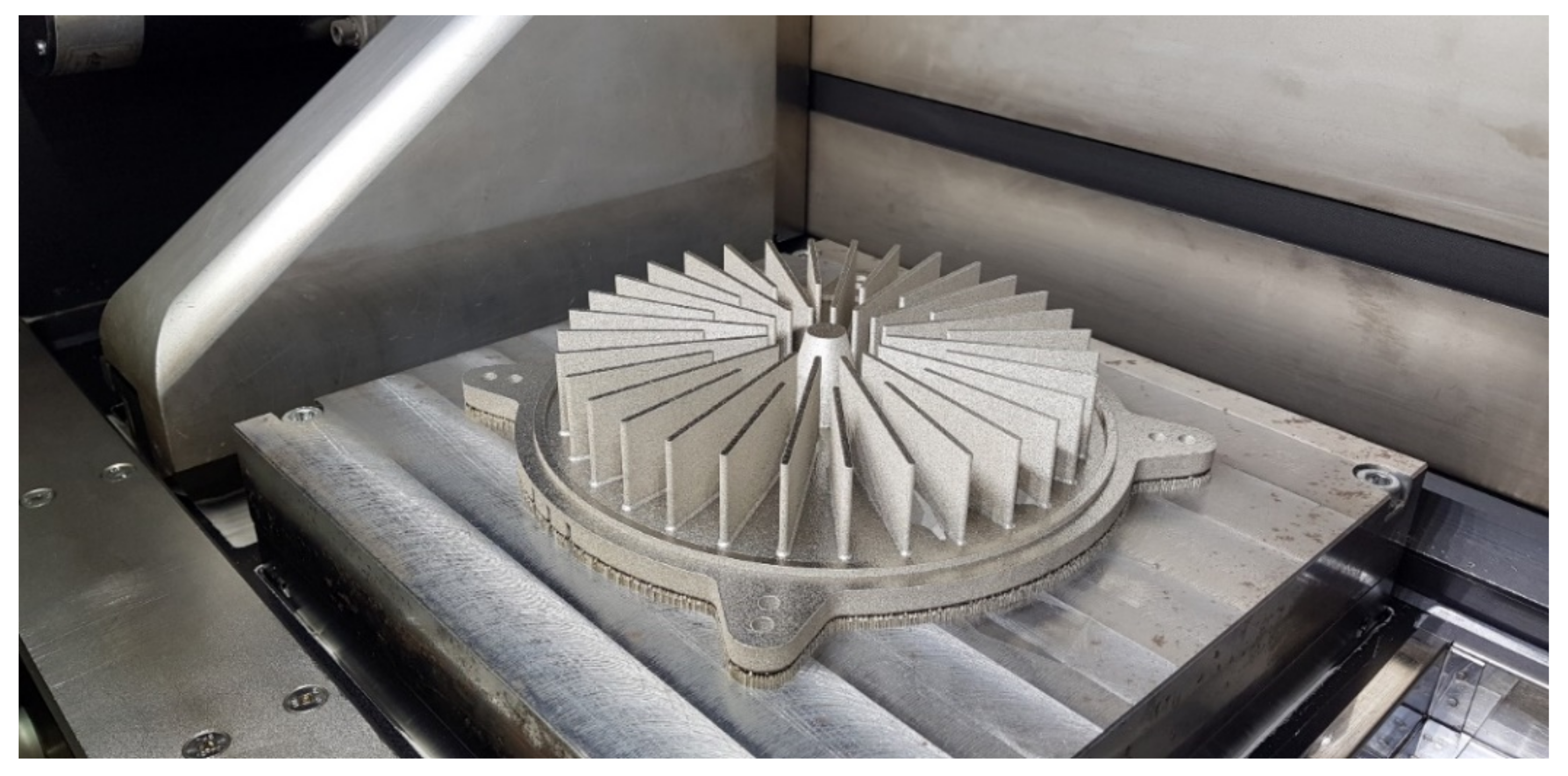
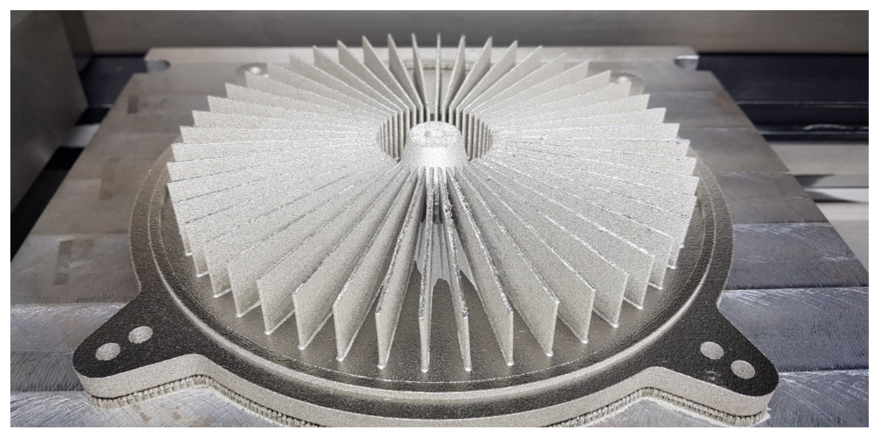
2.2. DMLS Part Manufacturing
2.3. Research Methodology Relevant to Geometrical Parameters
3. Results and Discussion
3.1. Comparison of the Obtained Results
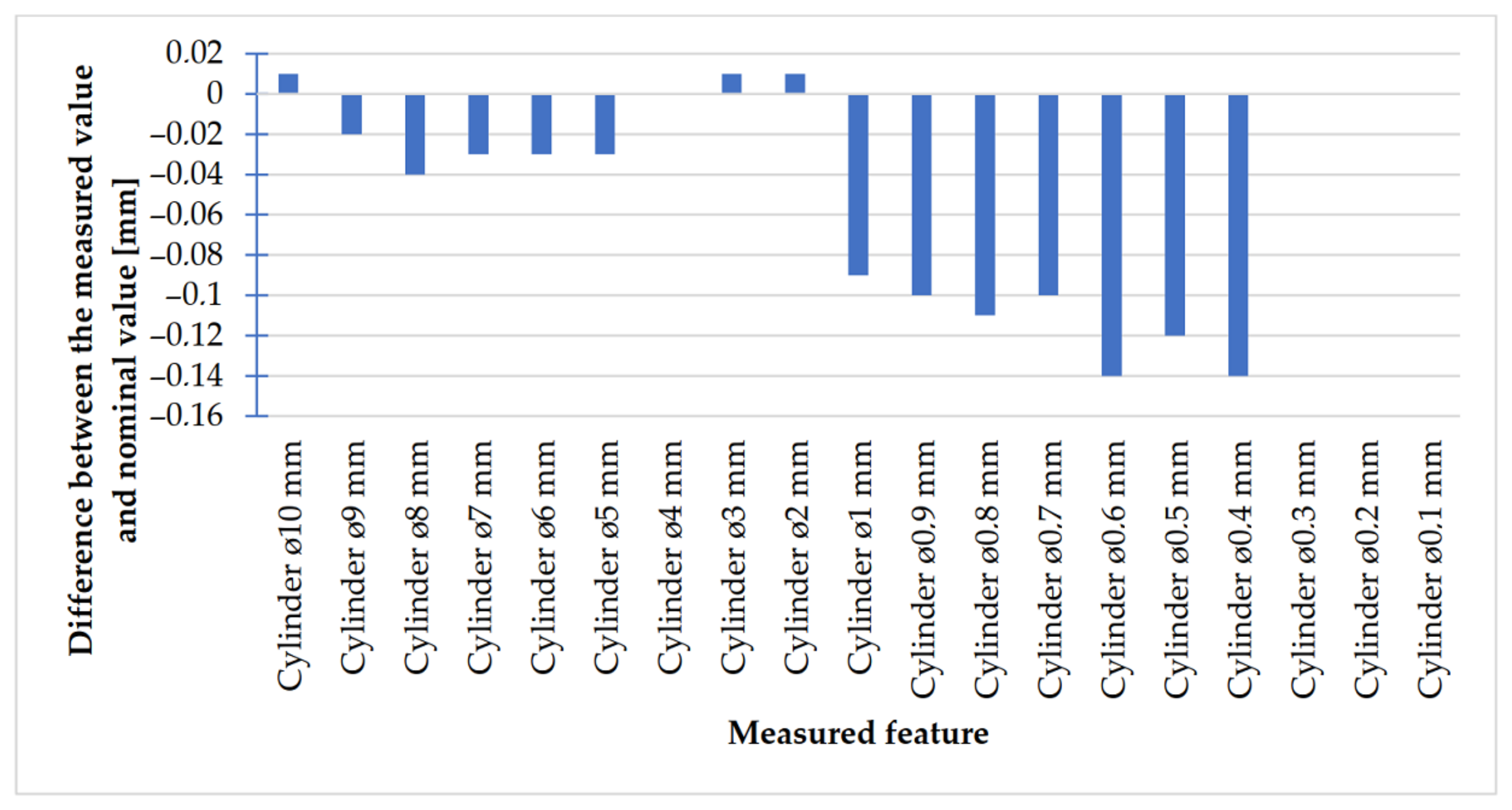
3.2. Comparison of the Difference between the Nominal and Measured Dimension
3.3. The Analysis of the Values of Means Deviations
4. Conclusions
Author Contributions
Funding
Data Availability Statement
Conflicts of Interest
References
- Gisario, A.; Kazarian, M.; Martina, F.; Mehrpouya, M. Metal additive manufacturing in the commercial aviation industry: A review. J. Manuf. Syst. 2019, 53, 124–149. [Google Scholar] [CrossRef]
- Elakkad, A.S. 3D Technology in the Automotive Industry. Int. J. Eng. Tech. Res. 2019, 8, 248–251. [Google Scholar] [CrossRef]
- Magerramova, L.; Vasilyev, B.; Kinzburskiy, V. Novel Designs of Turbine Blades for Additive Manufacturing. In Proceedings of the ASME Turbo Expo 2016: Turbine Technical Conference and Exposition, Seoul, Korea, 13–17 June 2016. [Google Scholar] [CrossRef]
- Siemiński, P.; Budzik, G. Additive Techniques. 3D Printing. 3D Printers [in Polish: Techniki Przyrostowe. Druk 3D. Drukarki 3D]; Oficyna Wydawnicza PW: Warszawa, Poland, 2015; pp. 11–28. [Google Scholar]
- Turek, P. Automating the process of designing and manufacturing polymeric models of anatomical structures of mandible with Industry 4.0 convention. Polimery 2019, 64, 522–529. [Google Scholar] [CrossRef]
- Rokicki, P.; Budzik, G.; Kubiak, K.; Bernaczek, J.; Dziubek, T.; Magniszewski, M.; Nowotnik, A.; Sieniawski, J.; Matysiak, H.; Cygan, R.; et al. Rapid prototyping in manufacturing of core models of aircraft engine blades. Aircr. Eng. Aerosp. Technol. 2014, 86, 323–332. [Google Scholar] [CrossRef]
- Rokicki, P.; Budzik, G.; Kubiak, K.; Dziubek, T.; Zaborniak, M.; Kozik, B.; Bernaczek, J.; Przeszlowski, L.; Nowotnik, A. The assessment of geometric accuracy of aircraft engine blades with the use of an optical coordinate scanner. Aircr. Eng. Aerosp. Technol. 2016, 88, 374–381. [Google Scholar] [CrossRef]
- Dilberoglu, U.M.; Gharehpapagh, B.; Yaman, U.; Dolen, M. The Role of Additive Manufacturing in the Era of Industry 4.0. Procedia Manuf. 2017, 11, 545–554. [Google Scholar] [CrossRef]
- Paszkiewicz, A.; Bolanowski, M.; Budzik, G.; Przeszłowski, Ł.; Oleksy, M. Process of Creating an Integrated Design and Manufacturing Environment as Part of the Structure of Industry 4.0. Processes 2020, 8, 1019. [Google Scholar] [CrossRef]
- Rayna, T.; Striukova, L. From rapid prototyping to home fabrication: How 3D printing is changing business model innovation. Technol. Forecast. Soc. Chang. 2016, 102, 214–224. [Google Scholar] [CrossRef] [Green Version]
- Anad, M.; Das, A.K. Issues in fabrication of 3D components through DMLS Technique: A review. Opt. Laser Technol. 2021, 139, 106914. [Google Scholar] [CrossRef]
- PN/EN ISO/ASTM 52900:2017-06 Additive Manufacturing–General Principles–Terminology. Available online: http://www.pkn.pl (accessed on 11 December 2020).
- Malladi, A.; Karunakaran, K. DMLS–An insight for unproblematic production. Mater. Today Proc. 2021, 37, 1986–1990. [Google Scholar] [CrossRef]
- Lu, Y.; Badarinath, R.; Lehtihet, E.A.; De Meter, E.C.; Simpson, T.W. Experimental sampling of the Z-axis error and laser positioning error of an EOSINT M280 DMLS machine. Addit. Manuf. 2018, 21, 501–516. [Google Scholar] [CrossRef]
- Wang, X.; Liu, Y.; Li, L.; Yenusah, C.O.; Xiao, Y.; Chen, L. Multi-scale phase-field modeling of layer-by-layer powder compact densification during solid-state direct metal laser sintering. Mater. Des. 2021, 203, 109615. [Google Scholar] [CrossRef]
- Badiru, A.B.; Valencia, V.V.; Liu, D. Additive Manufacturing Handbook: Product Development for the Defense Industry; CRC Press: Boca Raton, FL, USA, 2017; pp. 162–164. [Google Scholar]
- PN/EN ISO/ASTM 52901:2019-01 Additive Manufacturing–General Principles–Requirements Relevant to Parts Manufactured by Means of Additive Manufacturing (AM) Processes. Available online: http://www.pkn.pl (accessed on 18 December 2020).
- PN/EN ISO 17296-2:2016-10 Additive Manufacturing–General Principles–Part 2: Overview of Process Categories and Feedstock. Available online: http://www.pkn.pl (accessed on 21 December 2020).
- PN/EN ISO 17296-3:2016-10 Additive Manufacturing–General Principles–Part 3: Principal Characteristics and Appropriate Research Methods. Available online: http://www.pkn.pl (accessed on 21 December 2020).
- PN/EN ISO 17296-4:2016-10 Additive Manufacturing–General Principles–Part 4: Overview of Data Processing. Available online: http://www.pkn.pl (accessed on 21 December 2020).
- ISO/ASTM 52911-2:2019 Additive Manufacturing—Design—Part 2: Laser-Based Powder bed Fusion of Polymers. Available online: http://www.pkn.pl (accessed on 12 January 2021).
- ISO/ASTM 52902:2019 Additive Manufacturing—Test Artifacts—Geometric Capability Assessment of Additive Manufacturing Systems. Available online: http://www.pkn.pl (accessed on 18 January 2021).
- Kim, H.; Lin, Y.; Tseng, T.-L.B. A review on quality control in additive manufacturing. Rapid Prototyp. J. 2018, 24, 645–669. [Google Scholar] [CrossRef] [Green Version]
- Moon, W.; Kim, S.; Lim, B.-S.; Park, Y.-S.; Kim, R.J.-Y.; Chung, S.H. Dimensional Accuracy Evaluation of Temporary Dental Restorations with Different 3D Printing Systems. Materials 2021, 14, 1487. [Google Scholar] [CrossRef] [PubMed]
- Yoo, S.-Y.; Kim, S.-K.; Heo, S.-J.; Koak, J.-Y.; Kim, J.-G. Dimensional Accuracy of Dental Models for Three-Unit Prostheses Fabricated by Various 3D Printing Technologies. Materials 2021, 14, 1550. [Google Scholar] [CrossRef]
- Msallem, B.; Sharma, N.; Cao, S.; Halbeisen, F.S.; Zeilhofer, H.-F.; Thieringer, F.M. Evaluation of the Dimensional Accuracy of 3D-Printed Anatomical Mandibular Models Using FFF, SLA, SLS, MJ, and BJ Printing Technology. J. Clin. Med. 2020, 9, 817. [Google Scholar] [CrossRef] [Green Version]
- Dorweiler, B.; Baqué, P.E.; Chaban, R.; Ghazy, A.; Salem, O. Quality Control in 3D Printing: Accuracy Analysis of 3D-Printed Models of Patient-Specific Anatomy. Materials 2021, 14, 1021. [Google Scholar] [CrossRef]
- Kačmarčik, J.; Spahic, D.; Varda, K.; Porca, E.; Zaimovic-Uzunovic, N. An investigation of geometrical accuracy of desktop 3D printers using CMM. IOP Conf. Ser. Mater. Sci. Eng. 2018, 393, 012085. [Google Scholar] [CrossRef]
- Fahmy, A.R.; Becker, T.; Jekle, M. 3D printing and additive manufacturing of cereal-based materials: Quality analysis of starch-based systems using a camera-based morphological approach. Innov. Food Sci. Emerg. Technol. 2020, 63, 10238. [Google Scholar] [CrossRef]
- Guo, B.; Xu, Z.; Luo, X.; Bai, J. A detailed evaluation of surface, thermal, and flammable properties of polyamide 12/glass beads composites fabricated by multi jet fusion. Virtual Phys. Prototyp. 2021, 1–14. [Google Scholar] [CrossRef]
- Kopsacheilis, C.; Charalampous, P.; Kostavelis, I.; Tzovaras, D. In Situ Visual Quality Control in 3D Printing. In Proceedings of the 15th International Joint Conference on Computer Vision, Imaging and Computer Graphics Theory and Applications, Valletta, Malta, 27–29 February 2020. [Google Scholar] [CrossRef]
- Mitutoyo. Compendium of Metrology for Precision Measuring Instruments [In Polish: Kompendium Metrologii w Zakresie Precyzyjnych Przyrządów Pomiarowych]. Available online: https://www.mitutoyo.pl/application/files/1215/5888/6942/Mitutoyo_kompendium_metrologii_2013_WWW_opt_2.pdf (accessed on 30 March 2020).
- Vagovský, J.; Buranský, I.; Görög, A. Evaluation of Measuring Capability of the Optical 3D Scanner. Procedia Eng. 2015, 100, 1198–1206. [Google Scholar] [CrossRef] [Green Version]
- Dziubek, T.; Oleksy, M. Application of ATOS II optical system in the techniques of rapid prototyping of epoxy resin-based gear models. Polimery 2017, 62, 44–52. [Google Scholar] [CrossRef]
- Siraj, I.; Singh Bharti, P. Reliability analysis of a 3D Printing process. Procedia Comput. Sci. 2020, 173, 191–200. [Google Scholar] [CrossRef]
- Turek, P.; Budzik, G.; Sęp, J.; Oleksy, M.; Jóźwik, J.; Przeszłowski, Ł.; Paszkiewicz, A.; Kochmański, Ł.; Żelechowski, D. An Analysis of the Casting Polymer Mold Wear Manufactured Using PolyJet Method Based on the Measurement of the Surface Topography. Polymers 2020, 12, 3029. [Google Scholar] [CrossRef]
- Paraskevoudis, K.; Karayannis, P.; Koumoulos, E.P. Real-Time 3D Printing Remote Defect Detection (Stringing) with Computer Vision and Artificial Intelligence. Processes 2020, 8, 1464. [Google Scholar] [CrossRef]
- Octoprint. Available online: http://www.octoprint.org (accessed on 30 March 2020).
- Matzkanin, G.A. Selecting a nondestructive testing method: Visual inspection. AMMTIAC 2006, 1, 7–10. [Google Scholar]
- ISO/ASTM TR 52912:2020 Additive Manufacturing—Design—Functionally Graded Additive Manufacturing. Available online: http://www.pkn.pl (accessed on 5 January 2021).
- ISO/ASTM 52911-1:2019 Additive Manufacturing—Design—Part 1: Laser-Based Powder Bed Fusion of Metals. Available online: http://www.pkn.pl (accessed on 12 January 2021).


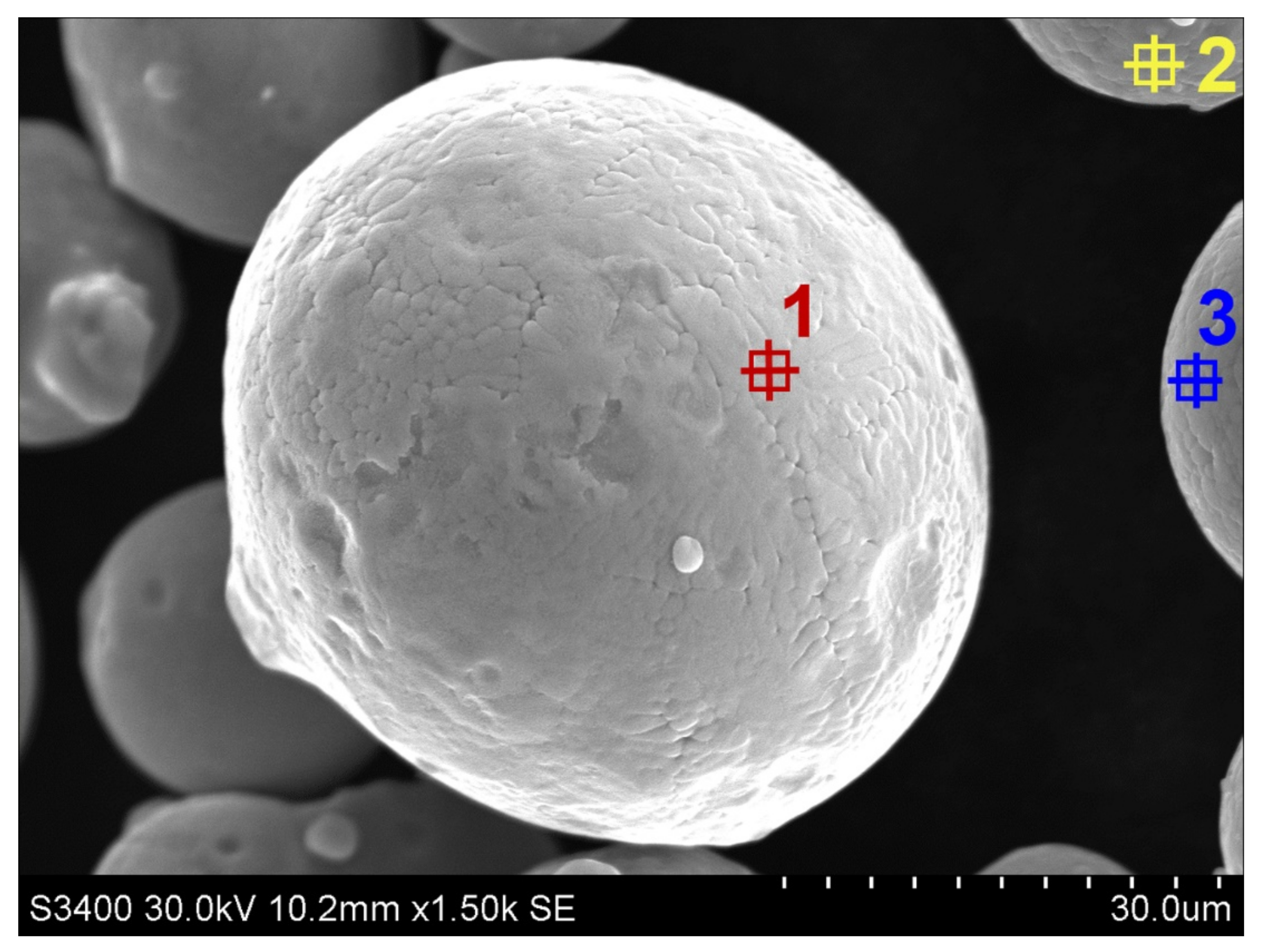
| Area | Si-K (%) | Cr-K (%) | Mn-K (%) | Fe-K (%) | Ni-K (%) | Cu-K (%) | Nb-K (%) | Ta-L (%) |
|---|---|---|---|---|---|---|---|---|
| 1 | 4.3 | 16.9 | 0.9 | 70.8 | 4.0 | 3.0 | 0.0 | 0.0 |
| 2 | 2.1 | 17.1 | 1.0 | 72.1 | 4.0 | 3.4 | 0.3 | 0.0 |
| 3 | 1.3 | 18.2 | 1.1 | 70.1 | 4.3 | 4.2 | 0.6 | 0.1 |
| Area | Si-K (%) | Cr-K (%) | Mn-K (%) | Fe-K (%) | Ni-K (%) | Cu-K (%) | Nb-K (%) | Ta-L (%) |
|---|---|---|---|---|---|---|---|---|
| 1 | 1.9 | 16.6 | 1.0 | 69.5 | 3.8 | 3.7 | 0.2 | 0.0 |
| 2 | 1.4 | 17.5 | 0.9 | 72.3 | 4.2 | 3.6 | 0.1 | 0.0 |
| 3 | 1.2 | 17.4 | 1.1 | 72.6 | 4.0 | 3.5 | 0.1 | 0.0 |
| 4 | 1.4 | 17.3 | 1.1 | 72.4 | 4.0 | 3.6 | 0.2 | 0.1 |
| Alloy designation | 17-4 (United States) 1.4542 (Europe) X5CrNiCuNb16-4 (Germany) |
| Geometric Data | |
| Minimum recommended layer thickness [µm] | 20 |
| Typical achievable part accuracy | a. ± 20 ÷ 50 µm (small parts) b. ± 0.2% (large parts) 1 |
| Minimum wall thickness [mm] | 0.3 ÷ 0.4 |
| Surface roughness | a. Ra: 2.5 ÷ 4.5 µm, Ry: 15 ÷ 40 µm (after shot-peening) b. Rz do < 0.5 µm (detail can be very finely polished) (after polishing) |
| Mechanical Properties of Parts | |
| Ultimate tensile strength [MPa] | a. min. 850, typical 930 ± 50 (XY); min. 850, typical 960 ± 50 (Z) 2 b. typical 1100 (XY); typical 980 (Z) 3 |
| Elongation at break [%] | a. min. 25, typical 31 ± 5 (XY); min. 25, typical 35 ± 5 (Z) 2 b. typical 29 (XY); typical 31 (Z) 3 |
| Modulus of elasticity (Young’s modulus) [GPa] | a. 170 ± 30 2 b. typical 180 3 |
| Upper yield strength [MPa] | a. min. 595, typical 645 ± 50 (XY); min. 580, typical 630 ± 50 (Z) 2 b. typical 634 (XY); typical 595 (Z) 3 |
| Lower yield strength [MPa] | a. min. 530, typical 586 ± 50 (XY); min. 530, typical 570 ± 50 (Z) 2 b. typical 590 (XY); typical 550 (Z) 3 |
| Hardness | a. as built: ok. 230 ± 20 HV1, i.e., approx. 18.0 ± 1.6 HRC ok. 250 HV1 ÷ 400 HV1, i.e., approx. 22.2 ÷ 40.8 HRC |
| No. | Description | Mark | View |
|---|---|---|---|
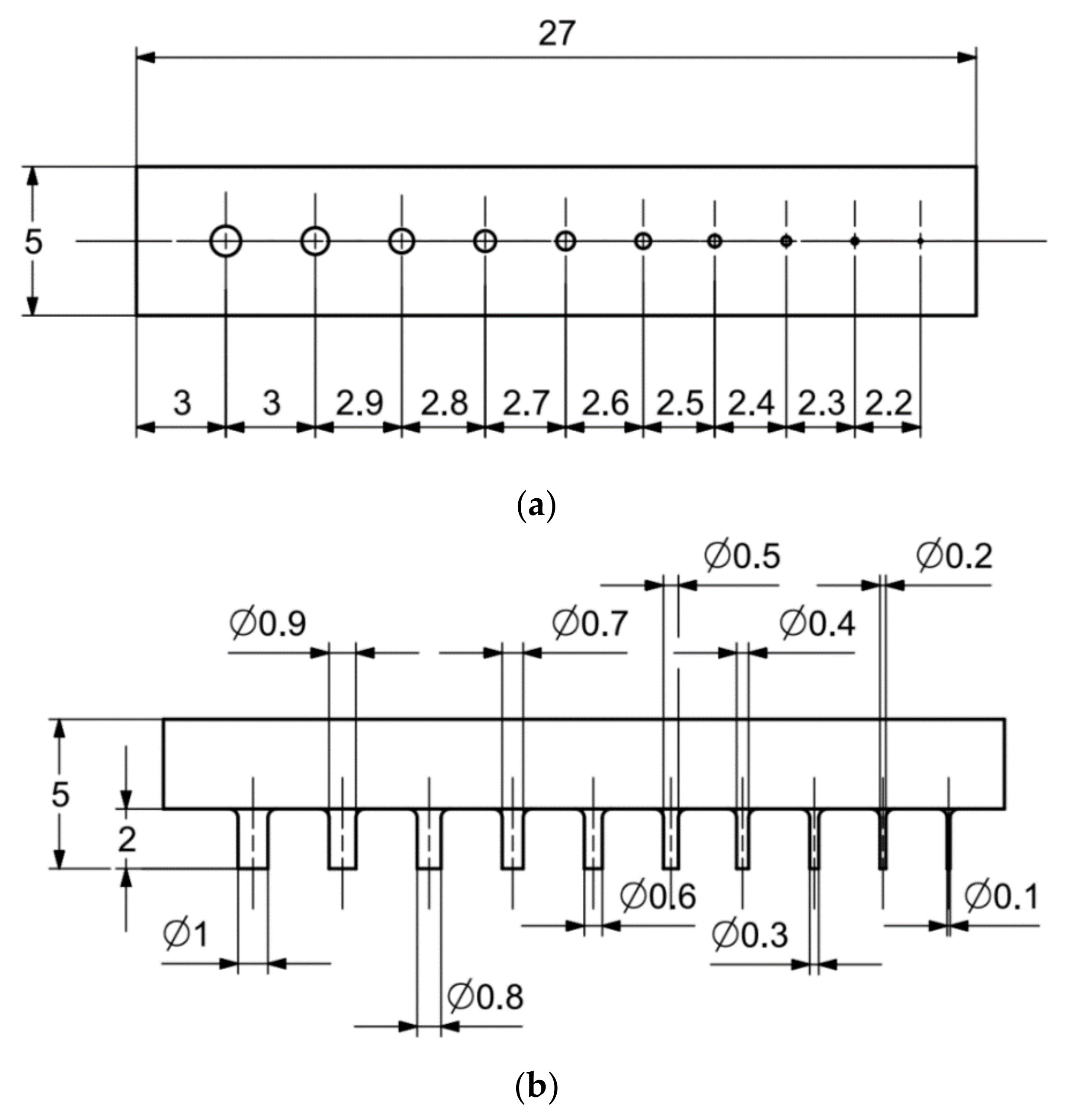
| 1. | base with cylindrical holes and cylinders with diameters from Ø10 to Ø2 mm and cylindrical holes with diameters from Ø1 to Ø0.1 mm | MB1 |  |
| 2. | base with cylinders with diameters from Ø1 to Ø0.1 mm | MB2 |  |
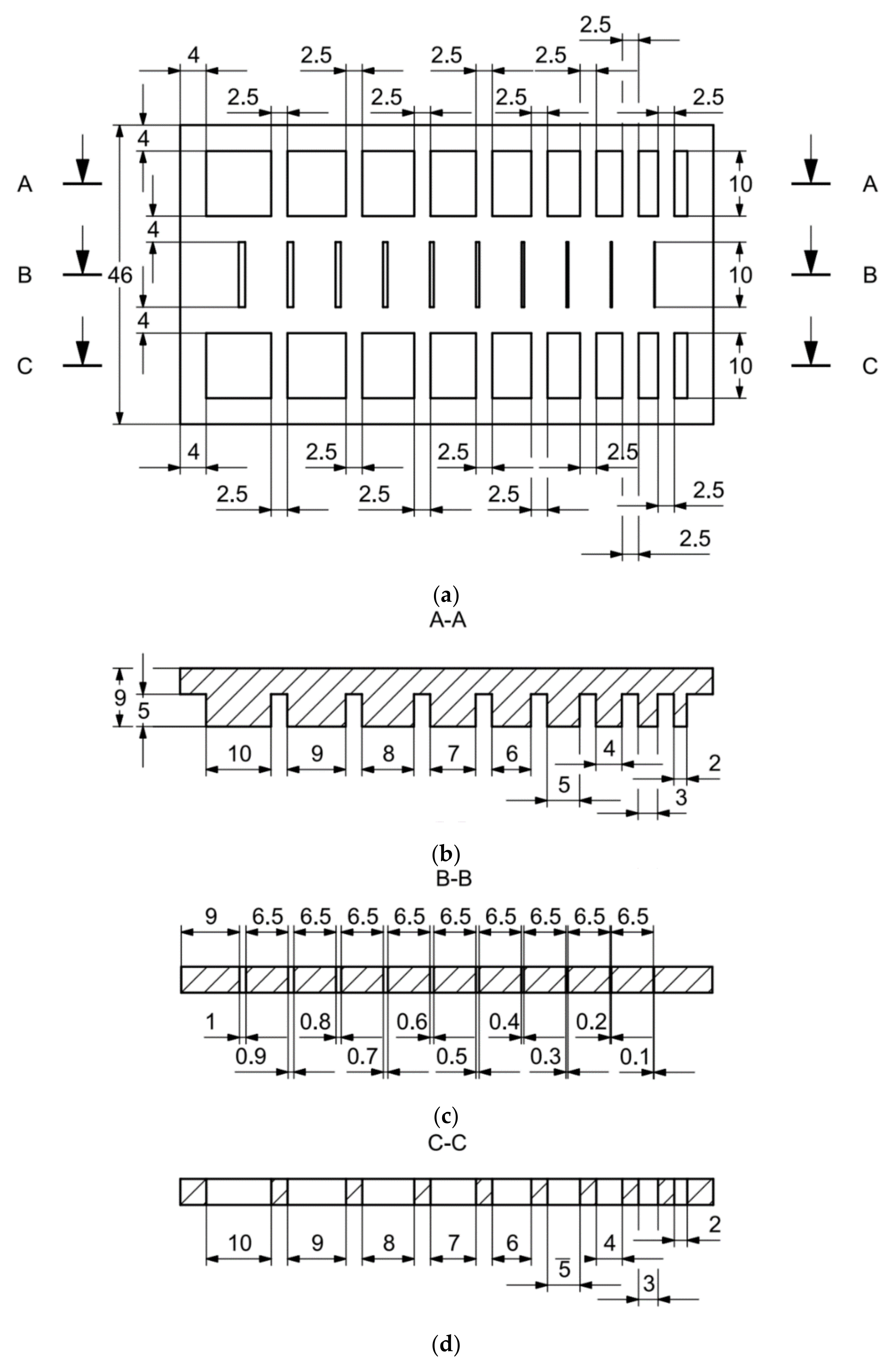
| 3. | base with cuboidal objects 10 to 2 mm wide and rectangular holes 10 to 2 mm wide and 1 to 0.1 mm wide | MB3 |  |
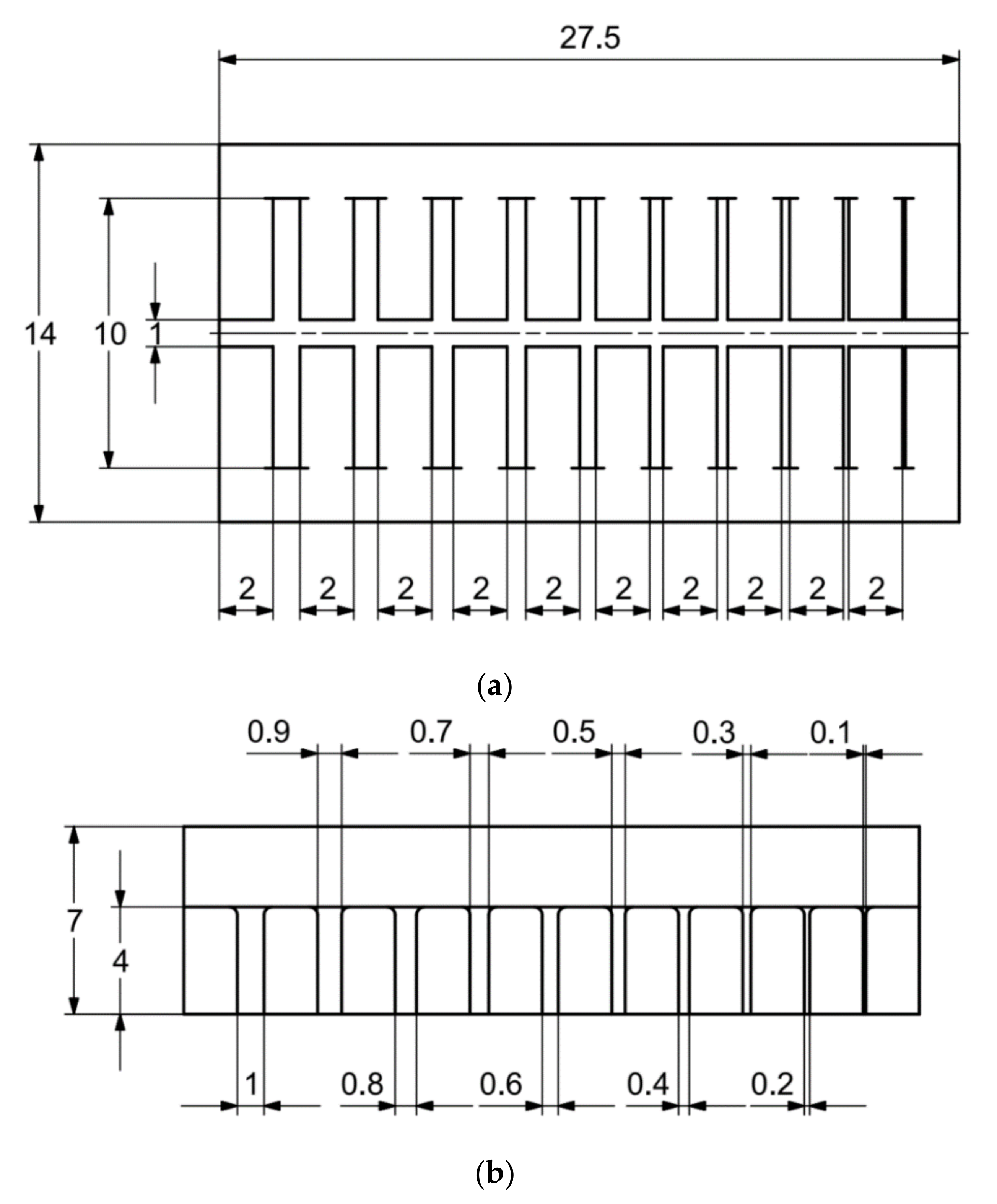
| 4. | base with cuboidal objects 1 to 0.1 mm wide | MB4 | 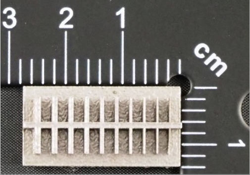 |
| Type of Parameter | Mark | Unit | Value |
|---|---|---|---|
| Layer thickness | d | (mm) | 0.2 |
| Laser power during sintering | Plaser | (W) | 180 |
| First contour sintering speed | vK1 | (mm/s) | 1200 |
| Value of the first contour offset from the CAD model contour | BO1 | (mm) | 0.06 |
| First contour sintering width | SB1 | (mm) | 0.09 |
| Sintering speed of the initial or final layers inside the contour | vH | (mm/s) | 1200 |
| Width of the inner layer melt with the contour of the initial and final layers | hH | (mm) | 0.1 |
| Core sintering speed | vK | (mm/s) | 1250 |
| Width of the inner layer melt input with the core layer contour | hK | (mm) | 0.08 |
| Sintering speed of the second contour coinciding with the contour of the CAD model | vK2 | (mm/s) | 2200 |
| Value of the second contour offset from the CAD model contour | BO2 | (mm) | 0.06 |
| Second contour sintering width | SB2 | (mm) | 0.08 |
| No. | Model | Measured Feature | Actual Value (B1) [mm] | Measurement Results [mm] | Arithmetic Mean of the Measurement Results (B2) [mm] | Difference between the Arithmetic Mean and the Actual Value (B2-B1) [mm] | ||
|---|---|---|---|---|---|---|---|---|
| 1 | 2 | 3 | ||||||
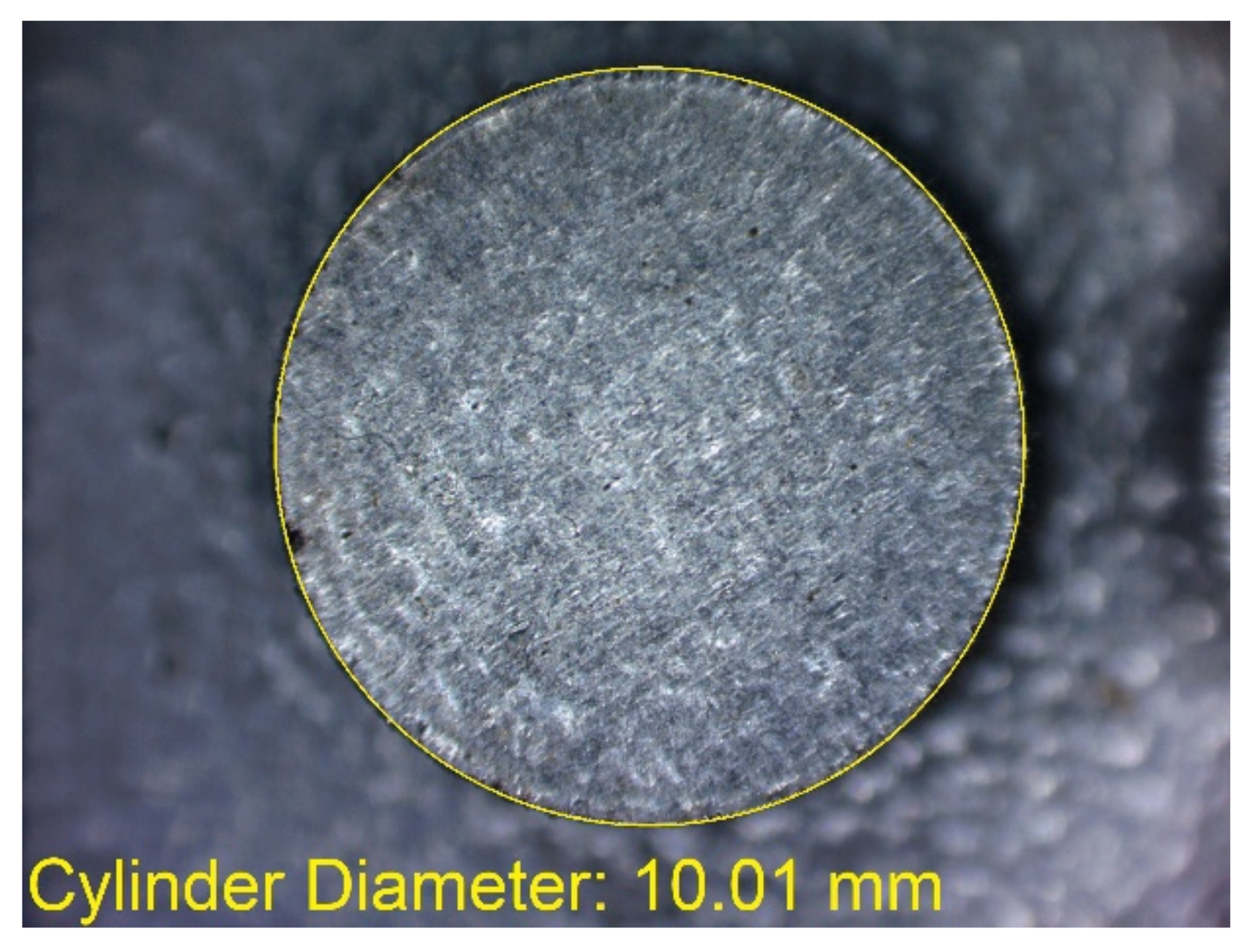
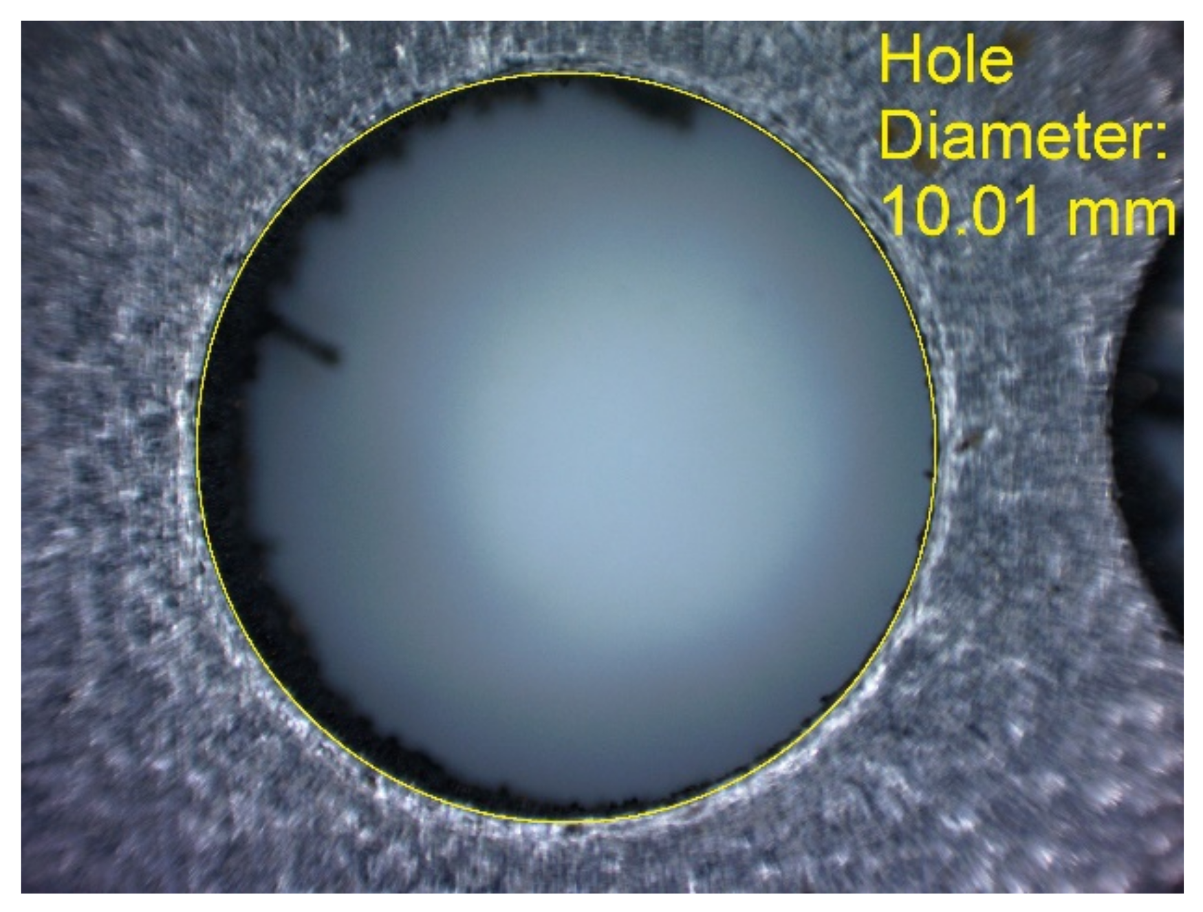
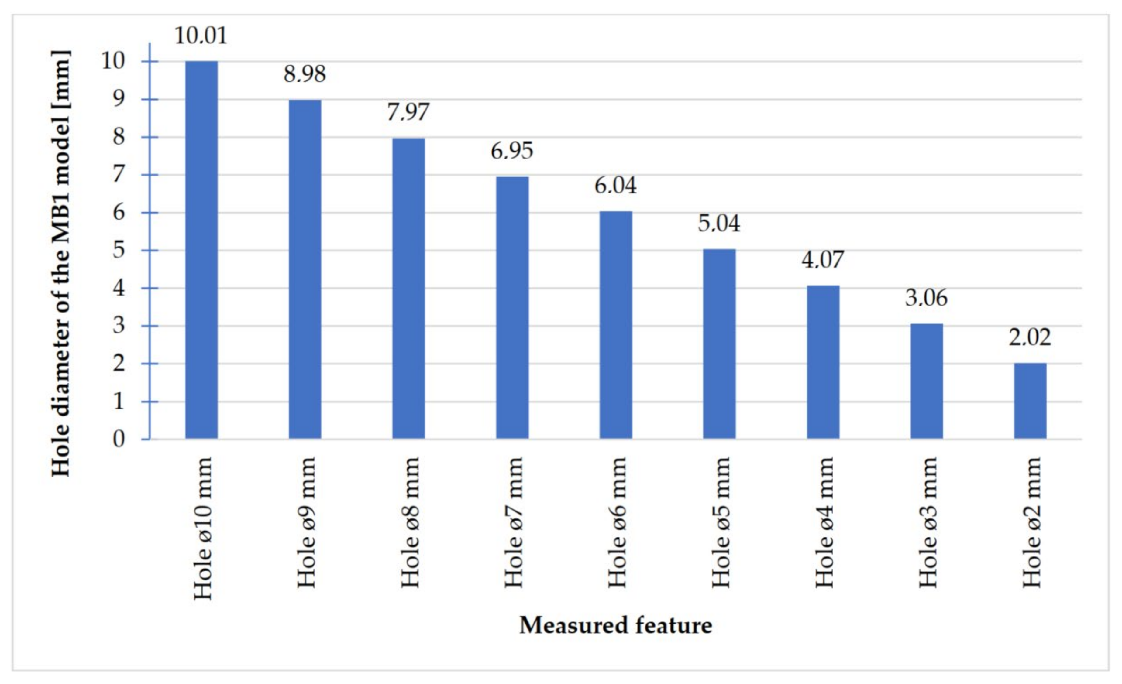
| 1 | MB1 | Hole Ø10 mm | 10 | 10.01 | 10.01 | 10.01 | 10.01 | 0.01 |
| Hole Ø9 mm | 9 | 8.98 | 9.00 | 8.98 | ≈8.99 | −0.01 | ||
| Hole Ø8 mm | 8 | 7.95 | 7.98 | 7.97 | ≈7.97 | −0.03 | ||
| Hole Ø7 mm | 7 | 6.95 | 6.95 | 6.95 | 6.95 | −0.05 | ||
| Hole Ø6 mm | 6 | 6.02 | 5.99 | 6.04 | ≈6.02 | 0.02 | ||
| Hole Ø5 mm | 5 | 5.04 | 4.96 | 5.04 | ≈5.01 | 0.01 | ||
| Hole Ø4 mm | 4 | 4.07 | 4.09 | 4.07 | ≈4.08 | 0.08 | ||
| Hole Ø3 mm | 3 | 3.00 | 3.06 | 3.06 | 3.04 | 0.04 | ||
| Hole Ø2 mm | 2 | 2.03 | 2.01 | 2.02 | 2.02 | 0.02 | ||
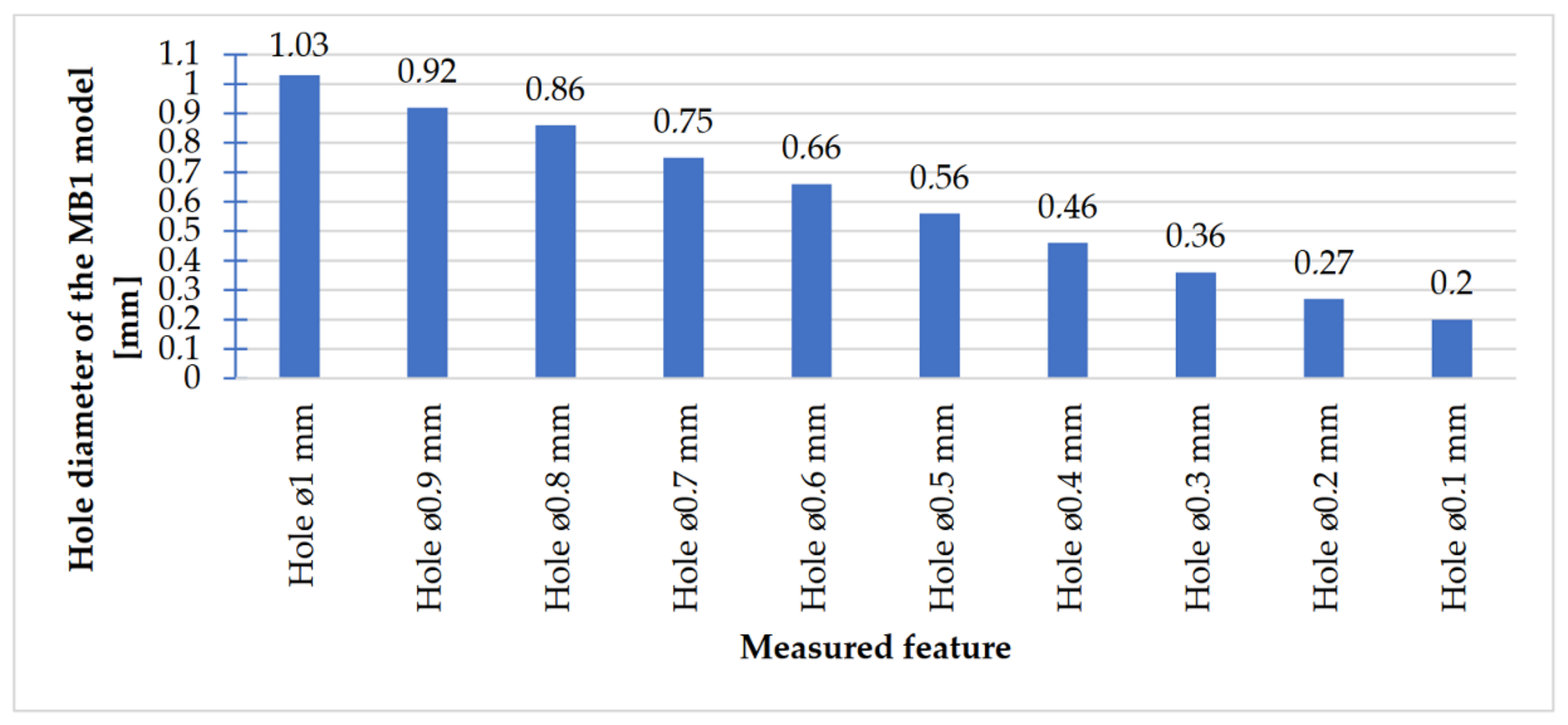
| Hole Ø1 mm | 1 | 1.03 | 1.02 | 1.04 | 1.03 | 0.03 | ||
| Hole Ø0.9 mm | 0.9 | 0.94 | 0.92 | 0.91 | ≈0.92 | 0.02 | ||
| Hole Ø0.8 mm | 0.8 | 0.84 | 0.88 | 0.87 | ≈0.86 | 0.06 | ||
| Hole Ø0.7 mm | 0.7 | 0.76 | 0.73 | 0.75 | ≈0.75 | 0.05 | ||
| Hole Ø0.6 mm | 0.6 | 0.66 | 0.65 | 0.68 | ≈0.66 | 0.06 | ||
| Hole Ø0.5 mm | 0.5 | 0.56 | 0.56 | 0.57 | ≈0.56 | 0.06 | ||
| Hole Ø0.4 mm | 0.4 | 0.46 | 0.46 | 0.46 | 0.46 | 0.06 | ||
| Hole Ø0.3 mm | 0.3 | 0.36 | 0.36 | 0.37 | ≈0.36 | 0.06 | ||
| Hole Ø0.2 mm | 0.2 | 0.27 | 0.26 | 0.28 | 0.27 | 0.07 | ||
| Hole Ø0.1 mm | 0.1 | 0.19 | 0.20 | 0.20 | ≈0.20 | 0.10 | ||
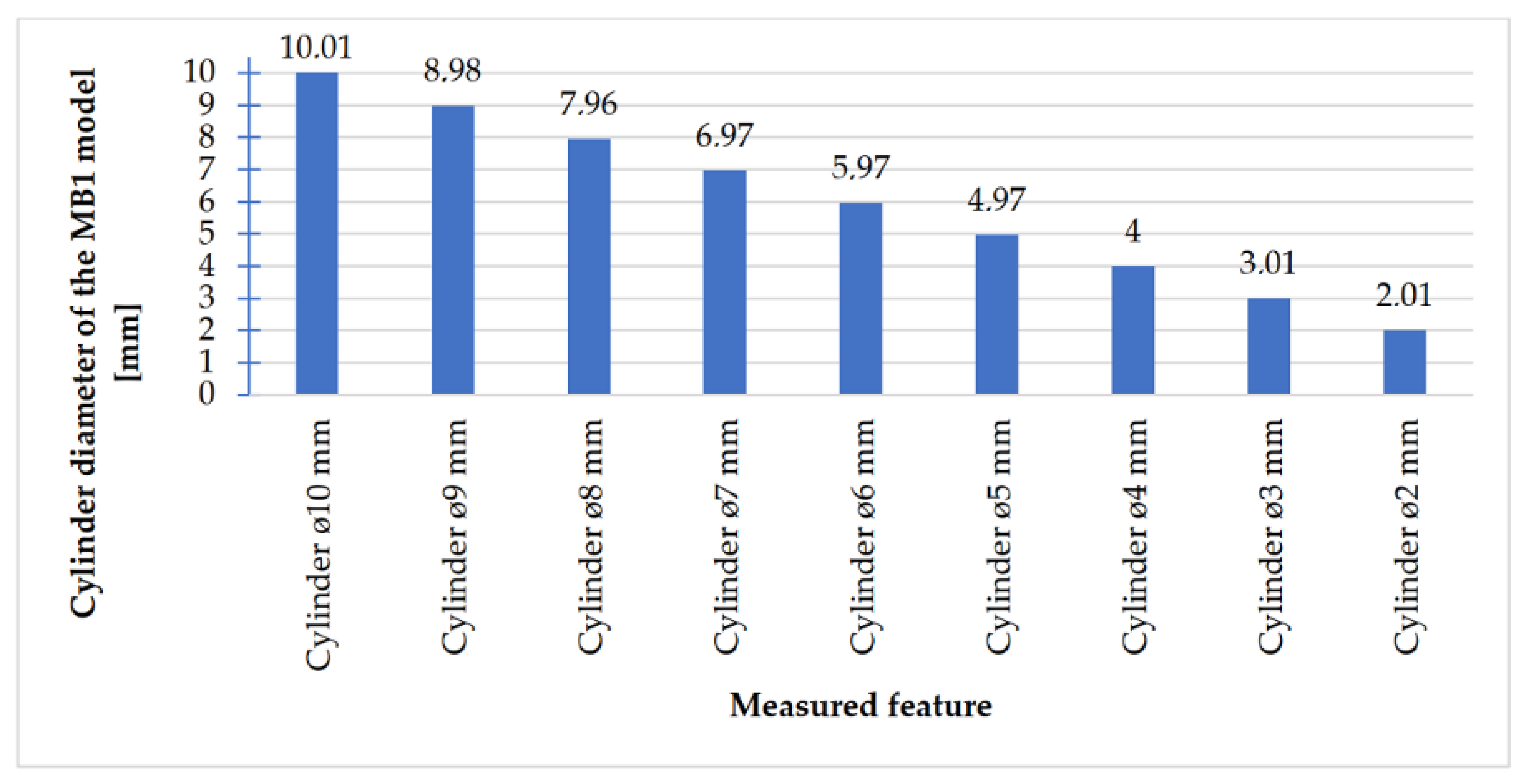
| Cylinder Ø10 mm | 10 | 10.01 | 9.99 | 10.03 | 10.01 | 0.01 | ||
| Cylinder Ø9 mm | 9 | 8.96 | 8.99 | 8.99 | 8.98 | −0.02 | ||
| Cylinder Ø8 mm | 8 | 7.96 | 7.97 | 7.96 | ≈7.96 | −0.04 | ||
| Cylinder Ø7 mm | 7 | 6.95 | 6.97 | 6.98 | ≈6.97 | −0.03 | ||
| Cylinder Ø6 mm | 6 | 5.98 | 5.95 | 5.97 | ≈5.97 | −0.03 | ||
| Cylinder Ø5 mm | 5 | 4.98 | 4.97 | 4.97 | ≈4.97 | −0.03 | ||
| Cylinder Ø4 mm | 4 | 4.00 | 4.01 | 3.99 | 4.00 | 0.00 | ||
| Cylinder Ø3 mm | 3 | 3.00 | 3.00 | 3.02 | ≈3.01 | 0.01 | ||
| Cylinder Ø2 mm | 2 | 2.01 | 2.02 | 2.00 | 2.01 | 0.01 | ||
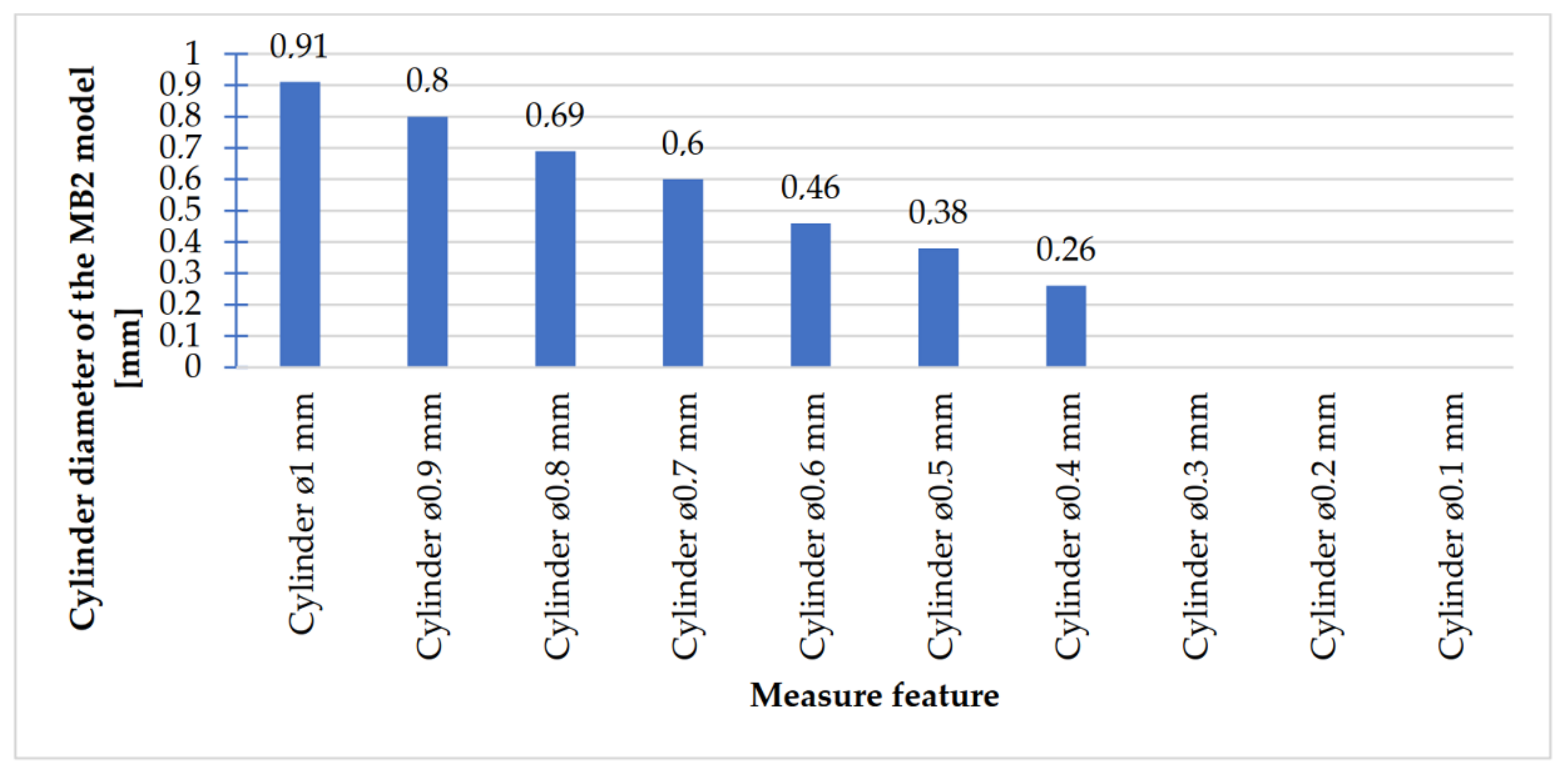
| 2 | MB2 | Cylinder Ø1 mm | 1 | 0.89 | 0.92 | 0.93 | ≈0.91 | −0.09 |
| Cylinder Ø0.9 mm | 0.9 | 0.81 | 0.80 | 0.79 | 0.80 | −0.10 | ||
| Cylinder Ø0.8 mm | 0.8 | 0.69 | 0.70 | 0.68 | 0.69 | −0.11 | ||
| Cylinder Ø0.7 mm | 0.7 | 0.61 | 0.59 | 0.60 | 0.60 | −0.10 | ||
| Cylinder Ø0.6 mm | 0.6 | 0.46 | 0.45 | 0.46 | ≈0.46 | −0.14 | ||
| Cylinder Ø0.5 mm | 0.5 | 0.38 | 0.35 | 0.40 | ≈0.38 | −0.12 | ||
| Cylinder Ø0.4 mm | 0.4 | 0.26 | 0.25 | 0.26 | ≈0.26 | −0.14 | ||
| Cylinder Ø0.3 mm | 0.3 | cylinders impossible to measure | ||||||
| Cylinder Ø0.2 mm | 0.2 | |||||||
| Cylinder Ø0.1 mm | 0.1 | |||||||
| 3 | MB3 | Hole width 10 mm | 10 | 10.05 | 10.07 | 10.04 | ≈10.05 | 0.05 |
| Hole width 9 mm | 9 | 9.04 | 9.04 | 9.06 | ≈9.05 | 0.05 | ||
| Hole width 8 mm | 8 | 8.03 | 8.01 | 8.03 | ≈8.02 | 0.02 | ||
| Hole width 7 mm | 7 | 7.01 | 7.01 | 7.03 | ≈7.02 | 0.02 | ||
| Hole width 6 mm | 6 | 6.02 | 6.03 | 6.04 | 6.03 | 0.03 | ||
| Hole width 5 mm | 5 | 5.06 | 5.06 | 5.06 | 5.06 | 0.06 | ||
| Hole width 4 mm | 4 | 4.05 | 4.00 | 4.06 | ≈4.04 | 0.04 | ||
| Hole width 3 mm | 3 | 3.00 | 2.98 | 3.01 | ≈3.00 | 0.00 | ||
| Hole width 2 mm | 2 | 1.96 | 1.93 | 1.96 | 1.95 | −0.05 | ||
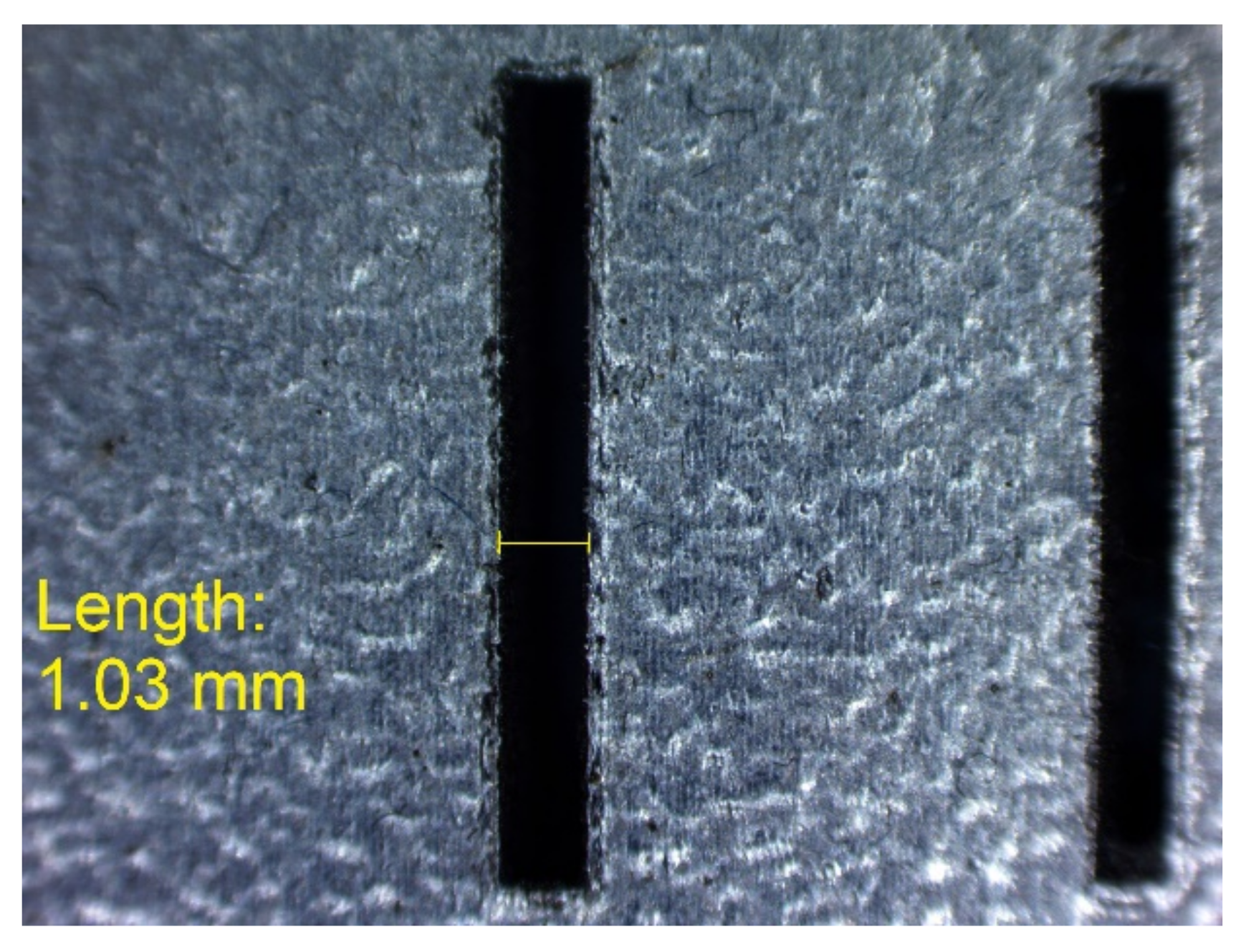
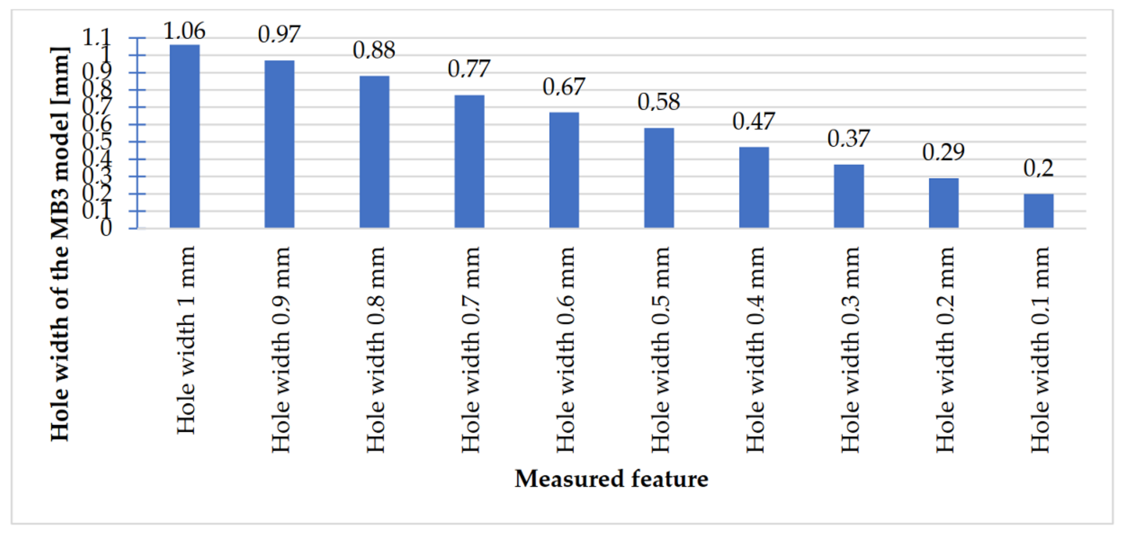
| Hole width 1 mm | 1 | 1.03 | 1.06 | 1.10 | ≈1.06 | 0.06 | ||
| Hole width 0.9 mm | 0.9 | 0.96 | 0.98 | 0.96 | ≈0.97 | 0.07 | ||
| Hole width 0.8 mm | 0.8 | 0.89 | 0.88 | 0.87 | 0.88 | 0.08 | ||
| Hole width 0.7 mm | 0.7 | 0.75 | 0.78 | 0.77 | ≈0.77 | 0.07 | ||
| Hole width 0.6 mm | 0.6 | 0.67 | 0.68 | 0.67 | ≈0.67 | 0.07 | ||
| Hole width 0.5 mm | 0.5 | 0.58 | 0.58 | 0.58 | 0.58 | 0.08 | ||
| Hole width 0.4 mm | 0.4 | 0.50 | 0.43 | 0.49 | ≈0.47 | 0.07 | ||
| Hole width 0.3 mm | 0.3 | 0.38 | 0.39 | 0.35 | ≈0.37 | 0.07 | ||
| Hole width 0.2 mm | 0.2 | 0.30 | 0.30 | 0.28 | ≈0.29 | 0.09 | ||
| Hole width 0.1 mm | 0.1 | 0.22 | 0.19 | 0.20 | ≈0.20 | 0.10 | ||
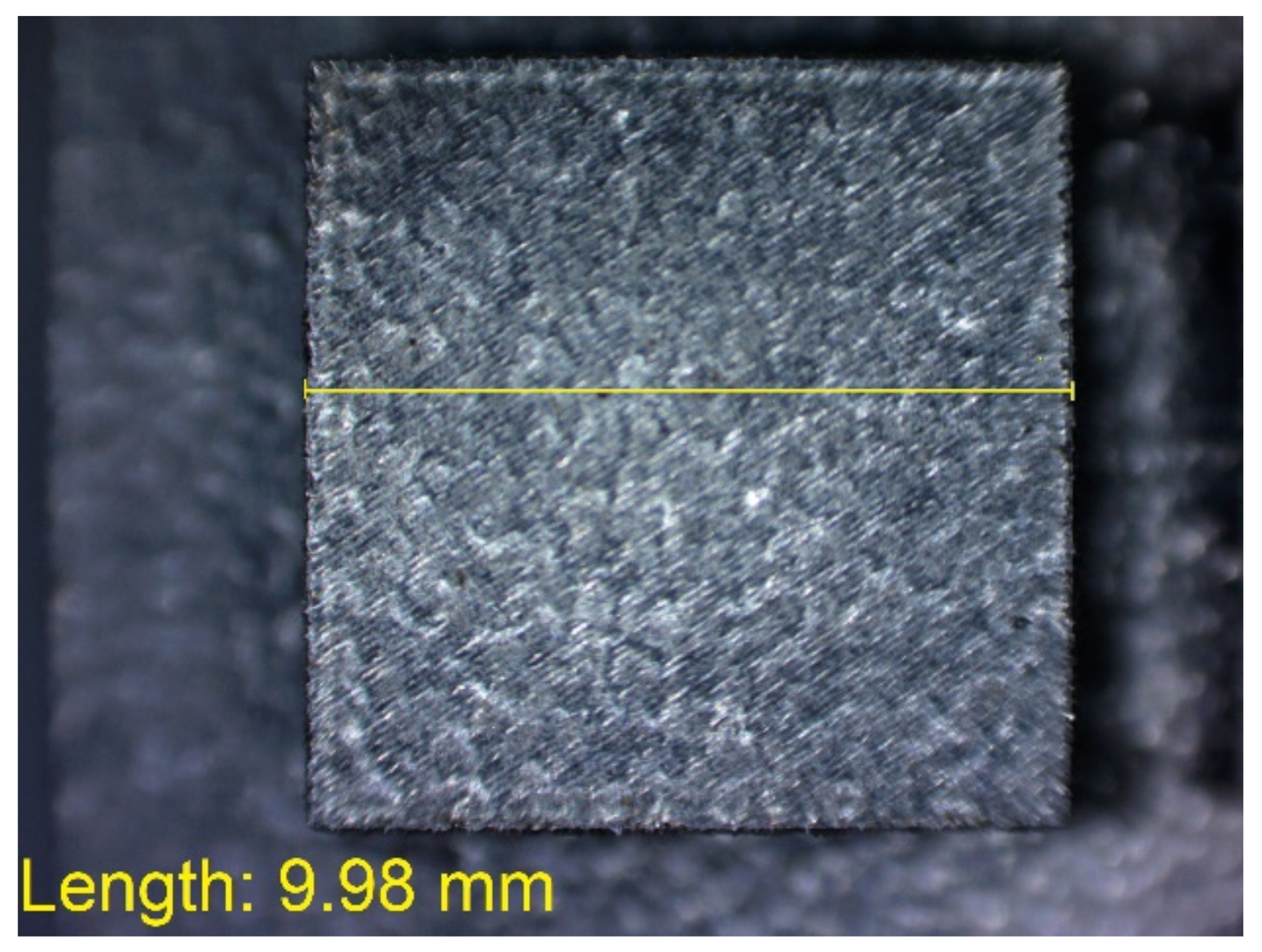
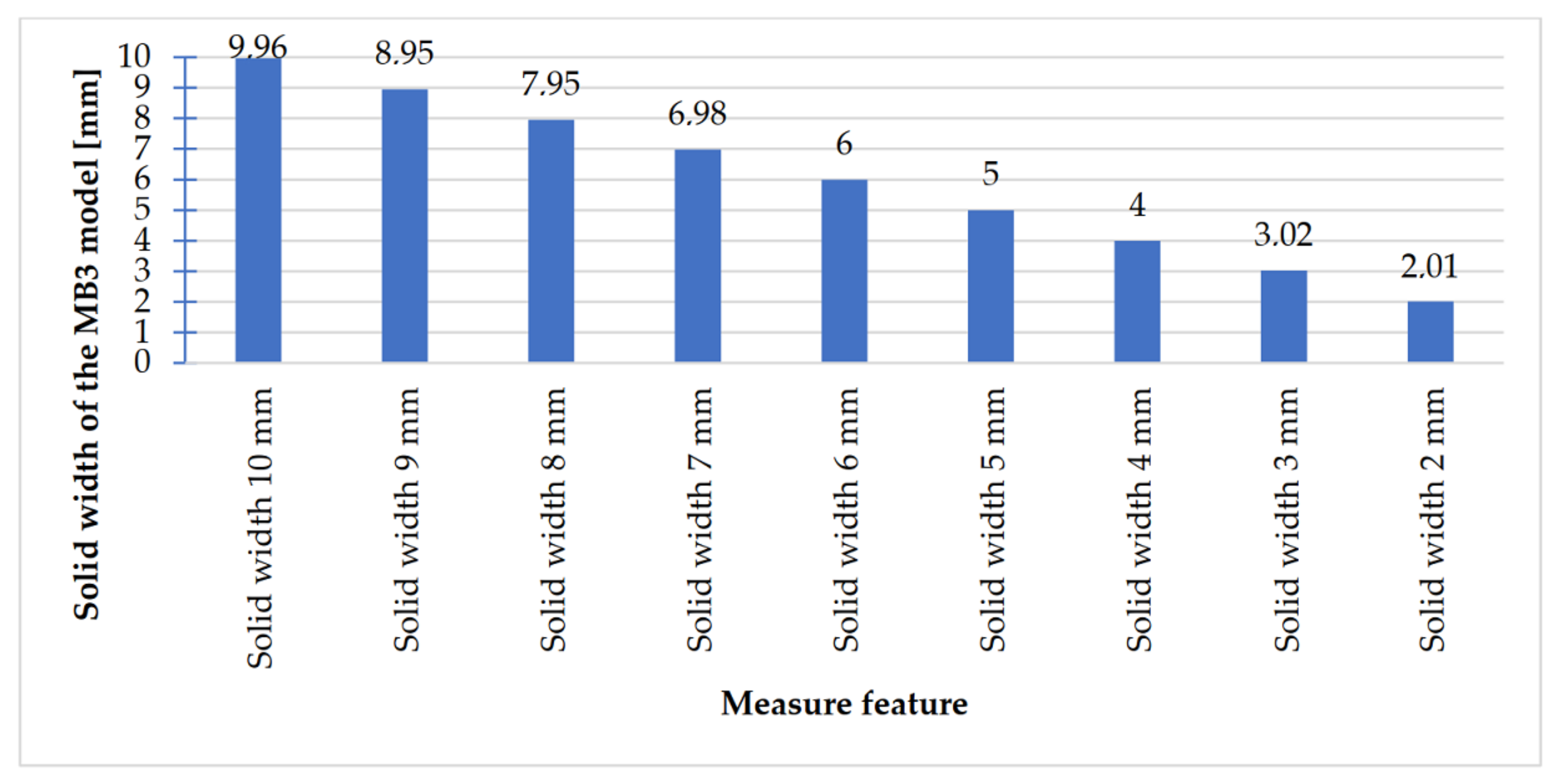
| Solid width 10 mm | 10 | 9.96 | 9.98 | 9.94 | 9.96 | −0.04 | ||
| Solid width 9 mm | 9 | 8.95 | 8.94 | 8.95 | ≈8.95 | −0.05 | ||
| Solid width 8 mm | 8 | 7.95 | 7.93 | 7.97 | 7.95 | −0.05 | ||
| Solid width 7 mm | 7 | 6.98 | 6.95 | 7.01 | 6.98 | −0.02 | ||
| Solid width 6 mm | 6 | 5.99 | 5.99 | 6.02 | 6.00 | 0.00 | ||
| Solid width 5 mm | 5 | 5.00 | 5.00 | 5.00 | 5.00 | 0.00 | ||
| Solid width 4 mm | 4 | 4.00 | 4.00 | 3.99 | ≈4.00 | 0.00 | ||
| Solid width 3 mm | 3 | 3.01 | 3.03 | 3.01 | ≈3.02 | 0.02 | ||
| Solid width 2 mm | 2 | 2.00 | 2.01 | 2.02 | 2.01 | 0.01 | ||
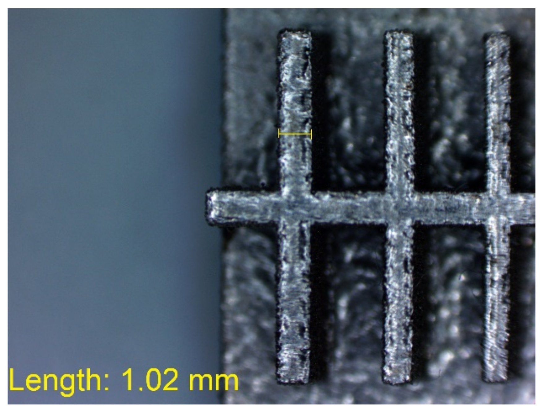
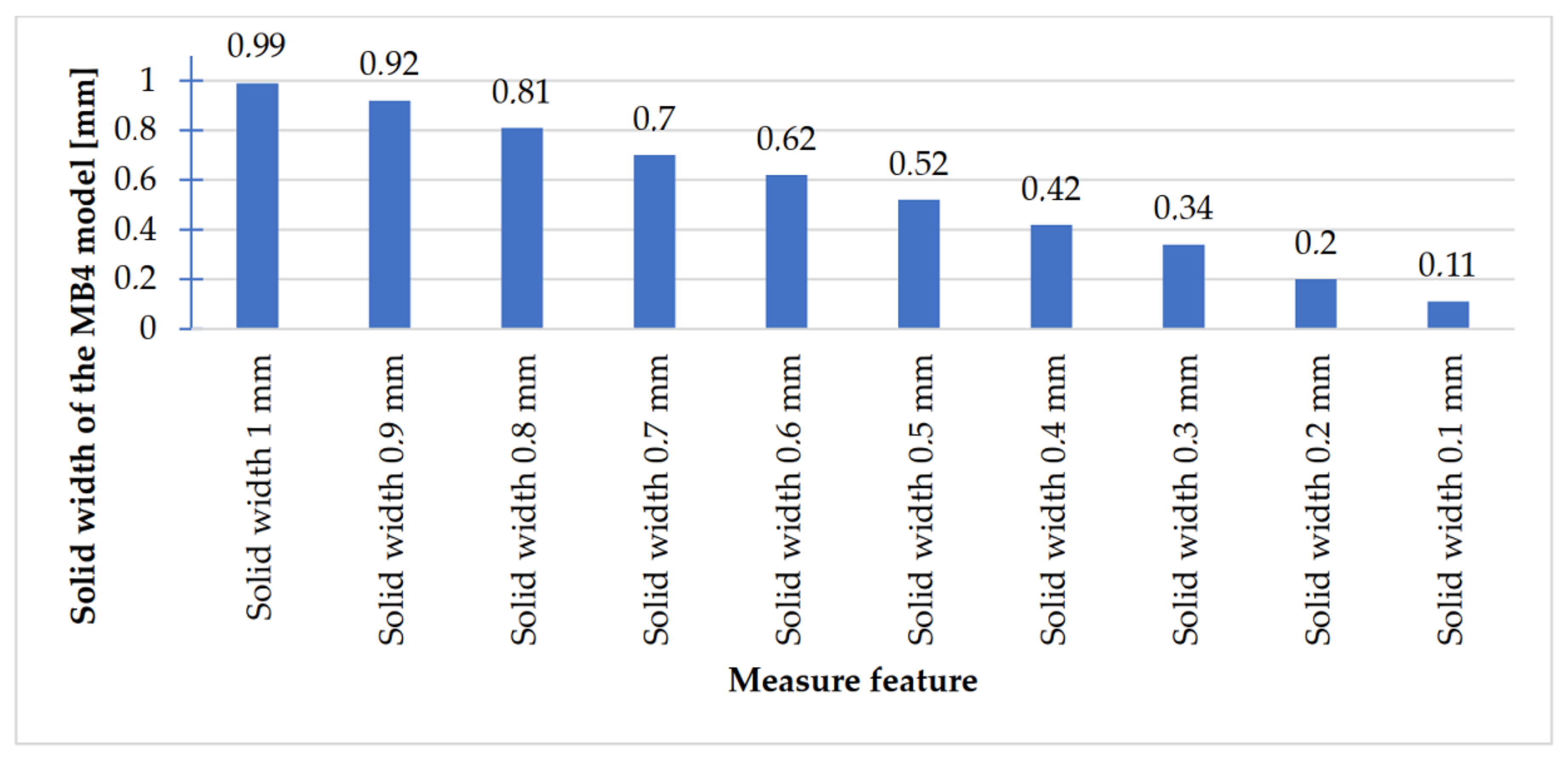
| 4 | MB4 | Solid width 1 mm | 1 | 1.02 | 0.98 | 0.98 | ≈0.99 | −0.01 |
| Solid width 0.9 mm | 0.9 | 0.92 | 0.93 | 0.91 | 0.92 | 0.02 | ||
| Solid width 0.8 mm | 0.8 | 0.81 | 0.82 | 0.80 | 0.81 | 0.01 | ||
| Solid width 0.7 mm | 0.7 | 0.72 | 0.71 | 0.68 | ≈0.70 | 0.00 | ||
| Solid width 0.6 mm | 0.6 | 0.59 | 0.62 | 0.64 | ≈0.62 | 0.02 | ||
| Solid width 0.5 mm | 0.5 | 0.50 | 0.52 | 0.54 | 0.52 | 0.02 | ||
| Solid width 0.4 mm | 0.4 | 0.38 | 0.44 | 0.44 | 0.42 | 0.02 | ||
| Solid width 0.3 mm | 0.3 | 0.34 | 0.36 | 0.33 | ≈0.34 | 0.04 | ||
| Solid width 0.2 mm | 0.2 | 0.20 | 0.20 | 0.20 | 0.20 | 0.00 | ||
| Solid width 0.1 mm | 0.1 | 0.10 | 0.10 | 0.13 | 0.11 | 0.01 | ||
| Research Prototype | Selected Parameters | |||
|---|---|---|---|---|
| The Largest Absolute Difference between the Nominal Dimension and the Measured * | Average Values of Deviations between the Nominal Dimension and the Measured | The Smallest Absolute Difference between the Nominal Dimension and Measured * | ||
| Cylindrical | Cylinders Ø0.1 mm ÷ Ø10 mm | 0.14 mm (Ø0.6; Ø0.4) | 0.04 mm | 0 mm (Ø4) |
| Holes Ø0.1 mm ÷ Ø10 mm | 0.10 mm (Ø0.1) | 0.03 mm | 0.01 mm (Ø10; Ø9; Ø5) | |
| Rectangular | Rectangular holes width 0.1 mm ÷ 10 mm | 0.10 mm (0.1) | 0.05 mm | 0 mm (3) |
| Rectangular solids width 0.1 mm ÷ 10 mm | 0.05 mm (8; 9) | 0 mm | 0 mm (6; 5; 4; 0.7; 0.2) | |
Publisher’s Note: MDPI stays neutral with regard to jurisdictional claims in published maps and institutional affiliations. |
© 2021 by the authors. Licensee MDPI, Basel, Switzerland. This article is an open access article distributed under the terms and conditions of the Creative Commons Attribution (CC BY) license (https://creativecommons.org/licenses/by/4.0/).
Share and Cite
Budzik, G.; Przeszłowski, Ł.; Dziubek, T.; Gontarz, M.; Dębski, M.; Smyk, E. Manufacturing Elements with Small Cross-Sections of 17-4 PH Steel (1.4542) with the Application of the DMLS Additive Manufacturing Method. Materials 2021, 14, 3256. https://doi.org/10.3390/ma14123256
Budzik G, Przeszłowski Ł, Dziubek T, Gontarz M, Dębski M, Smyk E. Manufacturing Elements with Small Cross-Sections of 17-4 PH Steel (1.4542) with the Application of the DMLS Additive Manufacturing Method. Materials. 2021; 14(12):3256. https://doi.org/10.3390/ma14123256
Chicago/Turabian StyleBudzik, Grzegorz, Łukasz Przeszłowski, Tomasz Dziubek, Małgorzata Gontarz, Mariusz Dębski, and Emil Smyk. 2021. "Manufacturing Elements with Small Cross-Sections of 17-4 PH Steel (1.4542) with the Application of the DMLS Additive Manufacturing Method" Materials 14, no. 12: 3256. https://doi.org/10.3390/ma14123256
APA StyleBudzik, G., Przeszłowski, Ł., Dziubek, T., Gontarz, M., Dębski, M., & Smyk, E. (2021). Manufacturing Elements with Small Cross-Sections of 17-4 PH Steel (1.4542) with the Application of the DMLS Additive Manufacturing Method. Materials, 14(12), 3256. https://doi.org/10.3390/ma14123256