
Phase Structure Evolution of the Fe-Al Arc-Sprayed Coating Stimulated by Annealing

 ,
,  , and
, and
Abstract
1. Introduction
2. Materials and Experimental Procedure
3. Results and Discussion
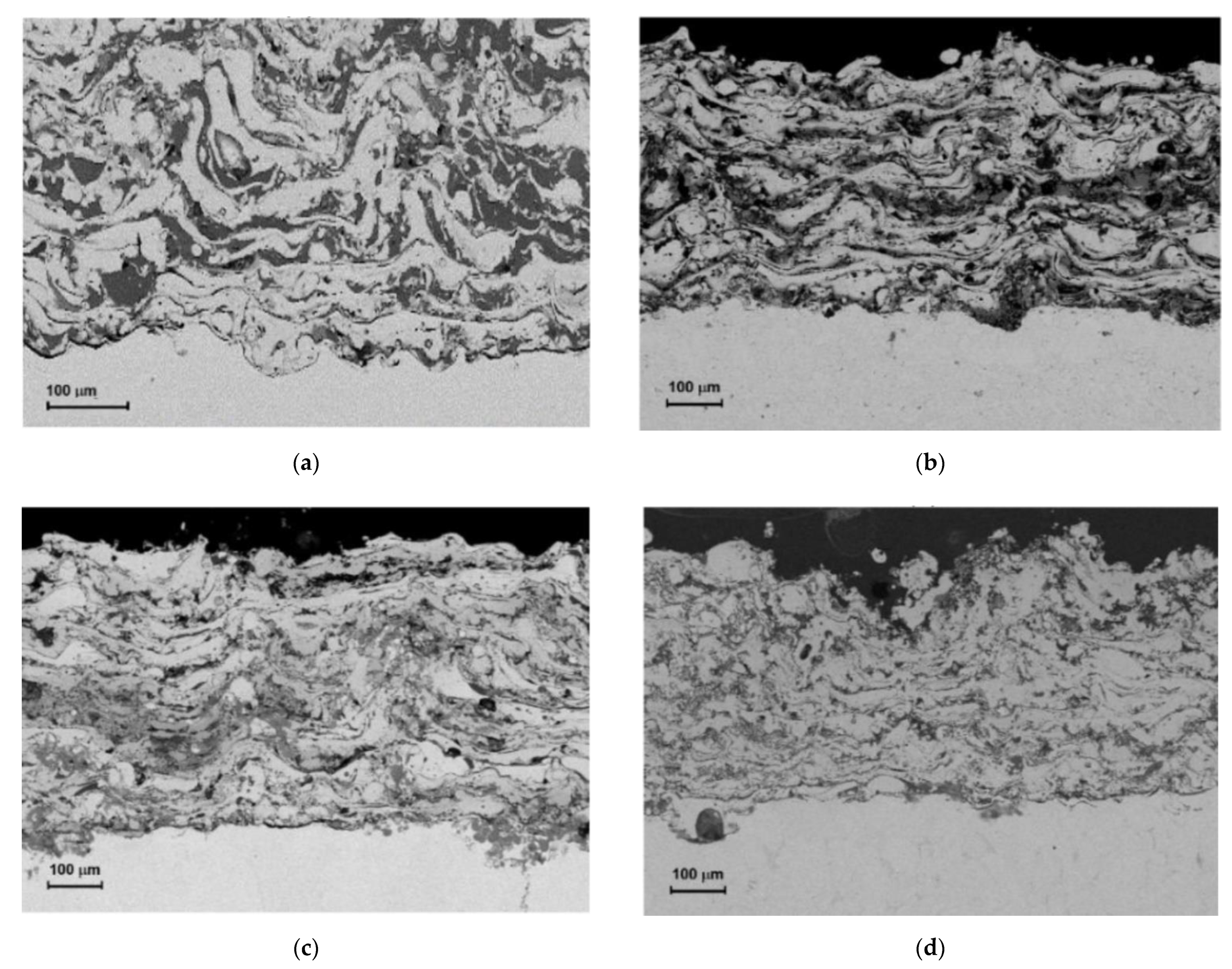
3.1. SEM Investigation of Annealed Coatings
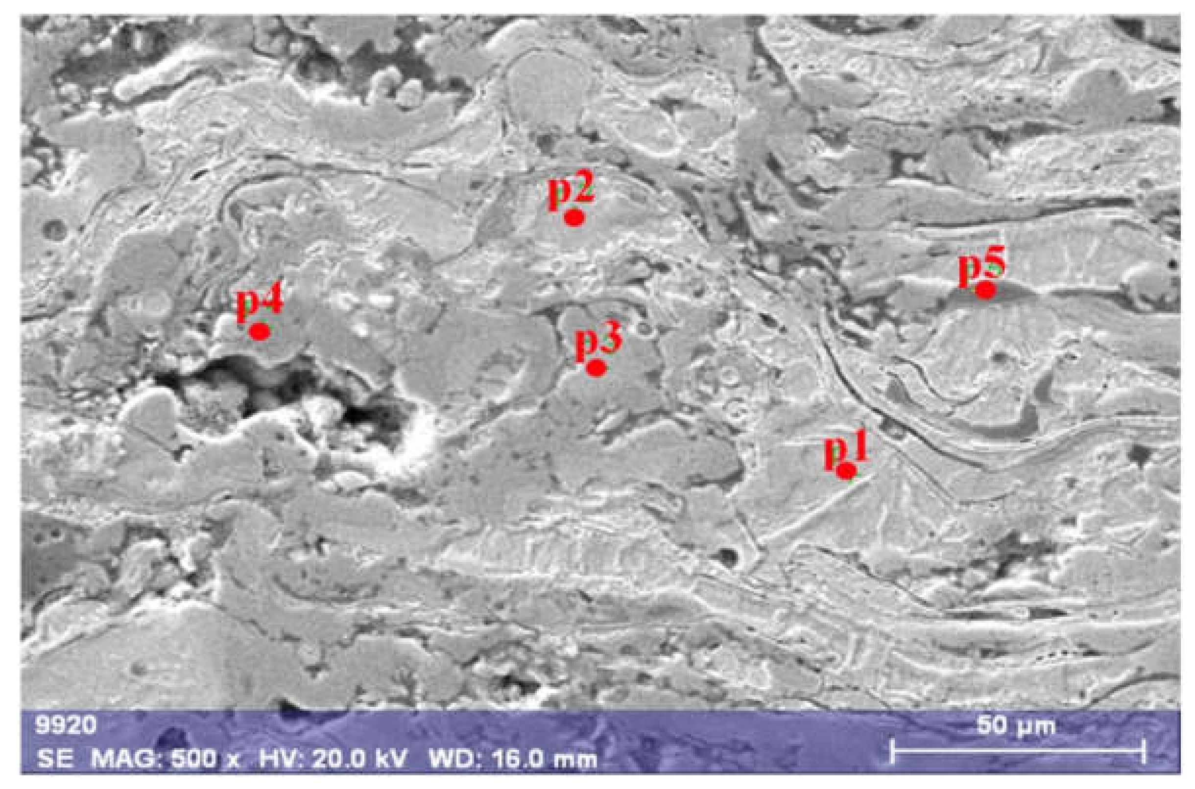
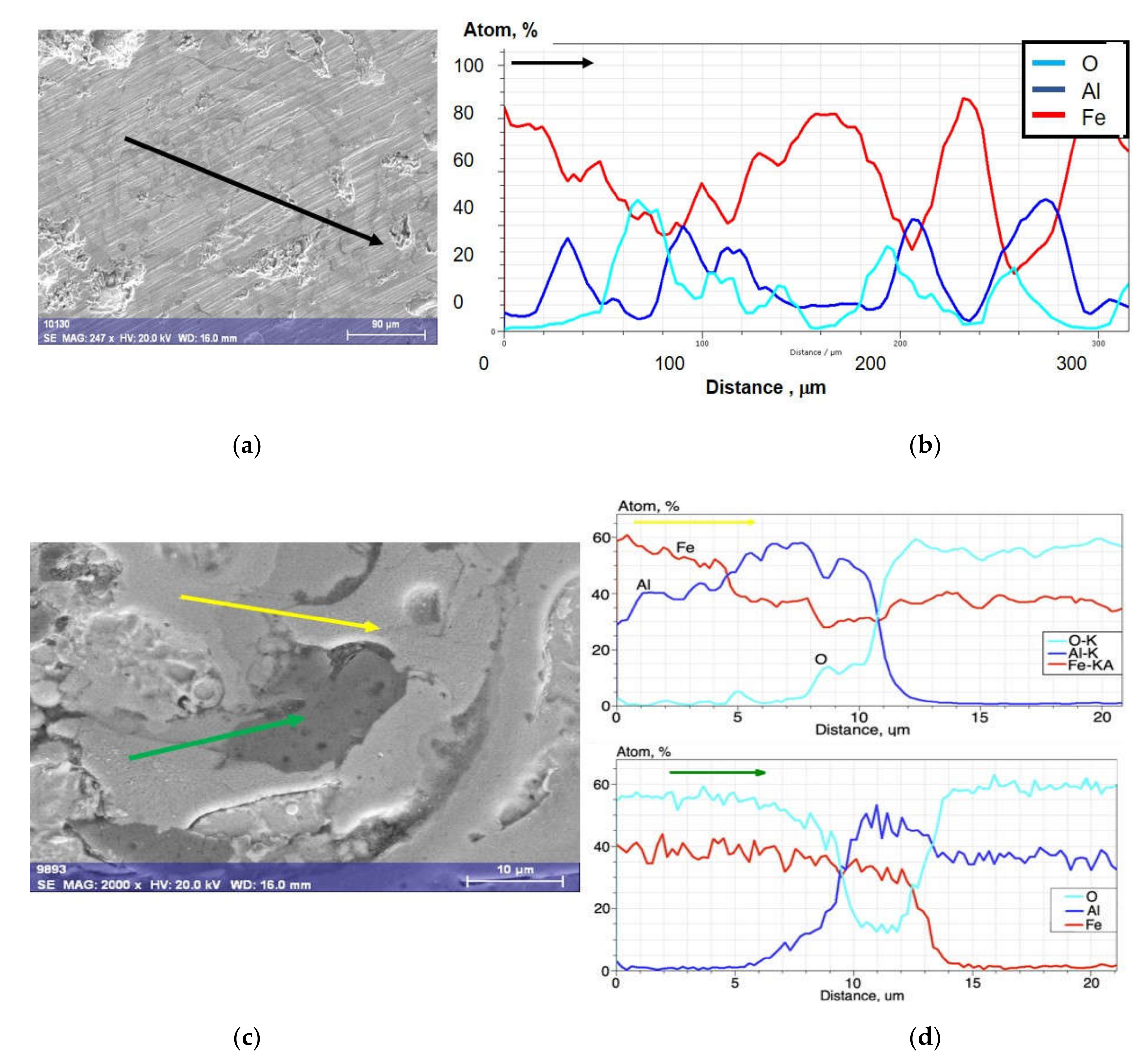
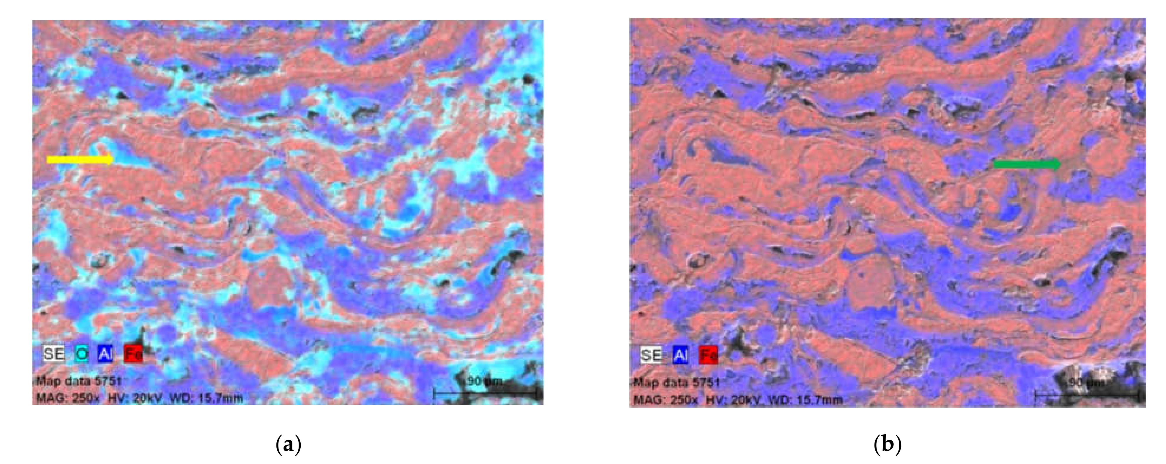
3.2. EDX Measurements
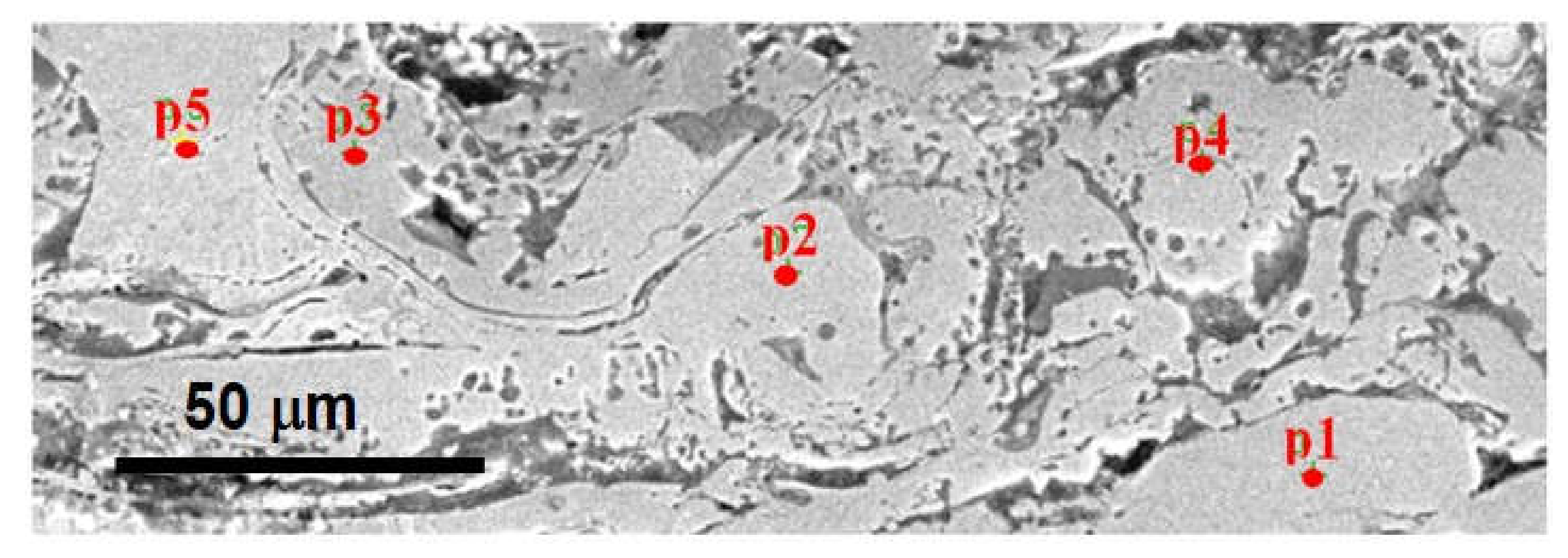
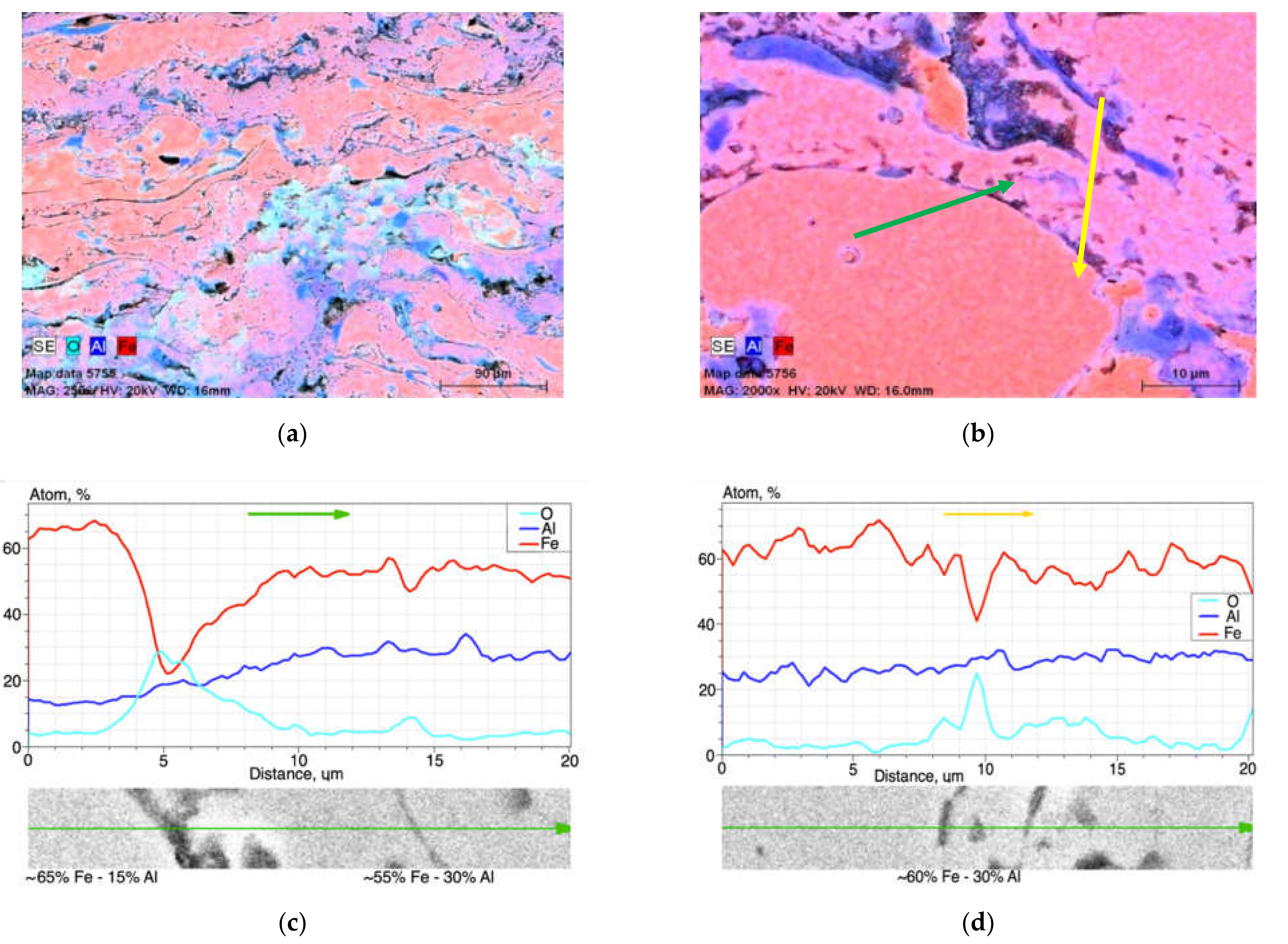
3.2.1. Arc-Sprayed Fe-Al-Type Coating Annealed at 700 °C


| Designation of Grain Area According to Figure 2 | Content, at. % | |||||||
|---|---|---|---|---|---|---|---|---|
| C | O | Al | Si | Mn | Fe | Au | Occurrence | |
| p1 | ~9 | ~1 | 6.47 | 0.48 | 0.66 | 81.49 | 0.15 | often |
| p2 | ~10 | - | 7.69 | 0.84 | 0.60 | 80.62 | 0.13 | often like p1 |
| p3 | ~12 | ~19 | 24.90 | 0.55 | 0.72 | 41.85 | 0.10 | rare |
| p4 | ~4 | ~51 | 6.33 | 0.29 | 0.38 | 36.25 | 0.09 | rare like p3 |
| p5 | ~15 | ~35 | 35.76 | 0.14 | 0.64 | 12.87 | 0.09 | very rare |
3.2.2. Arc-Sprayed Fe-Al-Type Coating Annealed at 800 °C


| Designation of Grain Area According to Figure 5. | Content, at.% | |||||||
|---|---|---|---|---|---|---|---|---|
| C | O | Al | Si | Mn | Fe | Au | Occurrence | |
| p1 | ~9 | - | 21.60 | 0.92 | 0.57 | 67.49 | 0.08 | often |
| p2 | ~8 | ~3 | 17.34 | 0.70 | 0.39 | 69.55 | 0.07 | often |
| p3 | ~9 | - | 32.86 | 0.40 | 0.32 | 56.63 | 0.21 | rare |
| p4 | ~9 | - | 25.84 | 0.74 | 0.53 | 63.18 | 0.09 | often |
| p5 | ~13 | ~8 | 13.93 | 0.63 | 0.43 | 62.99 | 0.26 | medium |
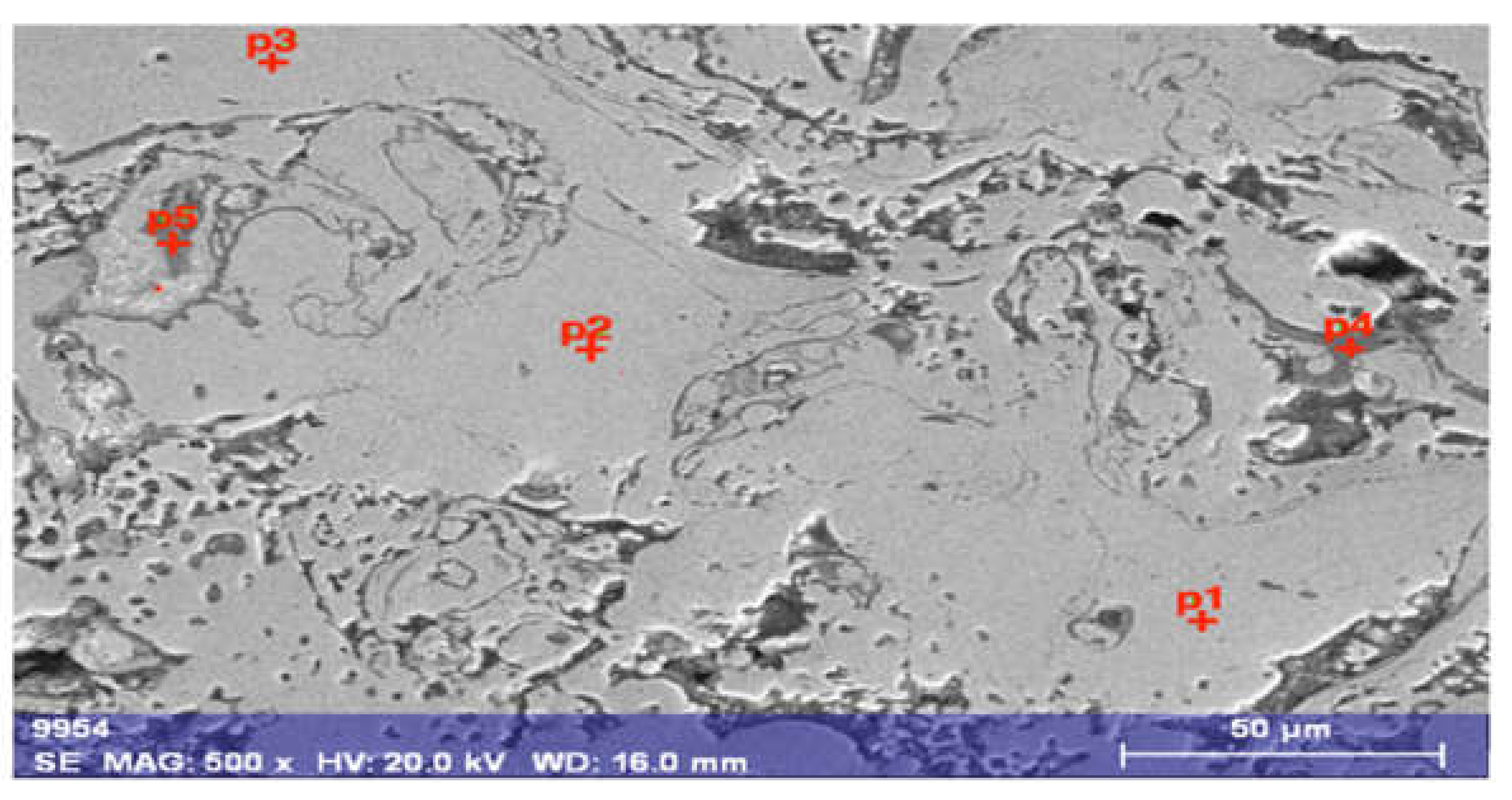
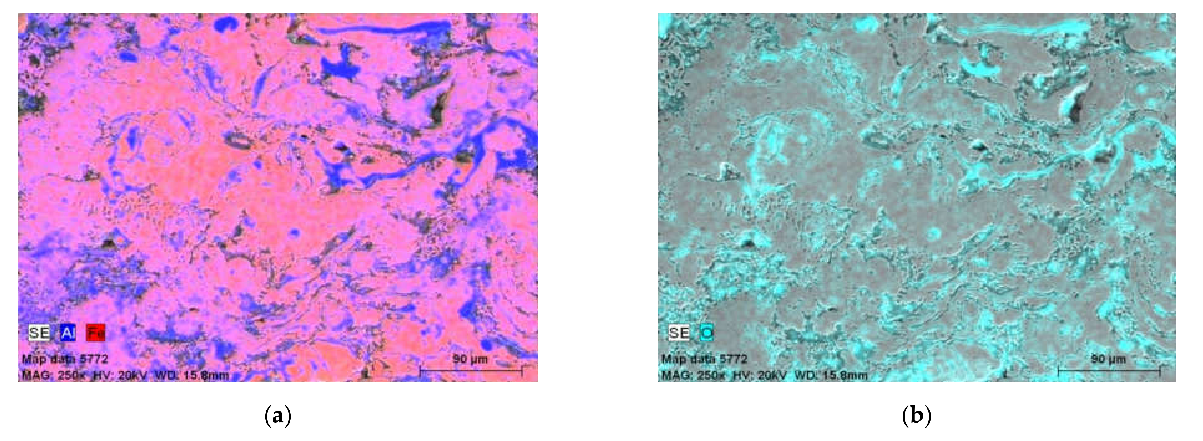
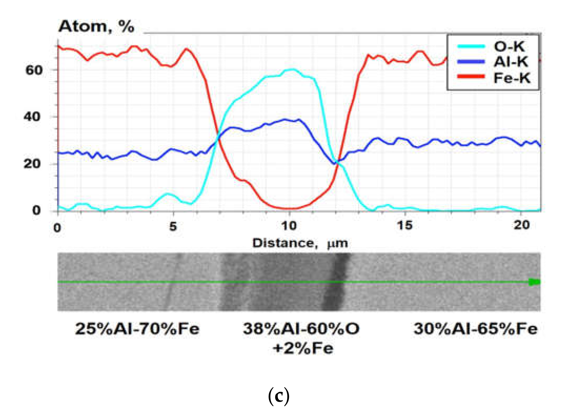
3.2.3. Arc-Sprayed Fe-Al-Type Sample 3 Annealed at 900 °C

| Designation of Grain Area According to Figure 7 | Content, at.% | |||||||
|---|---|---|---|---|---|---|---|---|
| C | O | Al | Si | Mn | Fe | Au | Occurrence | |
| p1 | ~15 | - | 21.86 | 0.55 | 0.64 | 61.78 | 0.10 | often |
| p2 | ~9 | - | 21.64 | 0.79 | 0.66 | 67.67 | 0.15 | often like p1 |
| p3 | ~8 | - | 23.57 | 0.48 | 0.63 | 67.11 | 0.14 | often like p1 |
| p4 | ~6 | ~56 | 34.62 | 0.21 | 0.94 | 1.22 | 0.05 | rare -precipitation |
| p5 | ~4 | ~55 | 34.47 | 0.04 | 0.23 | 4.47 | 0.08 | rare |
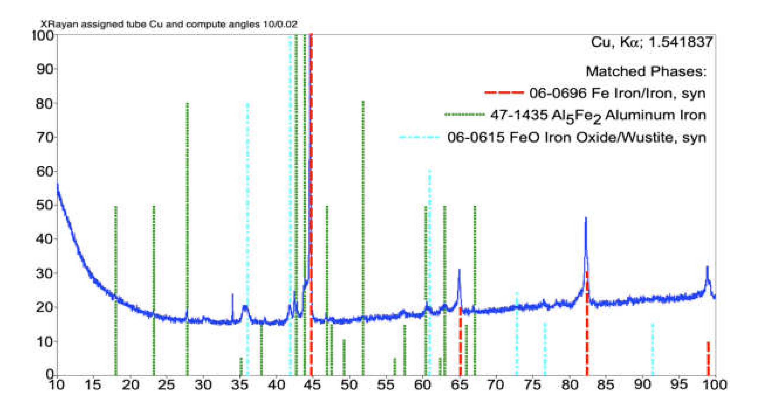
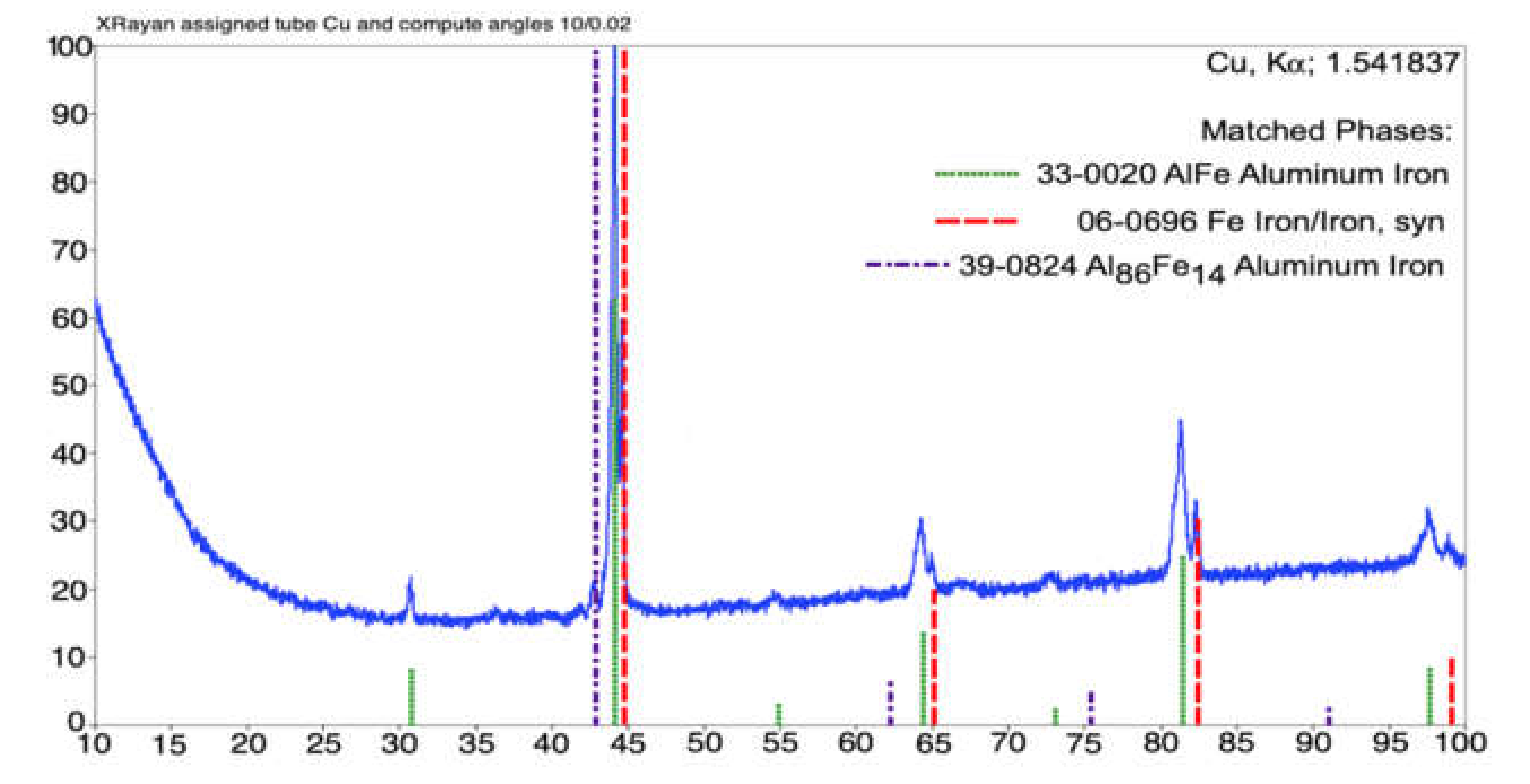
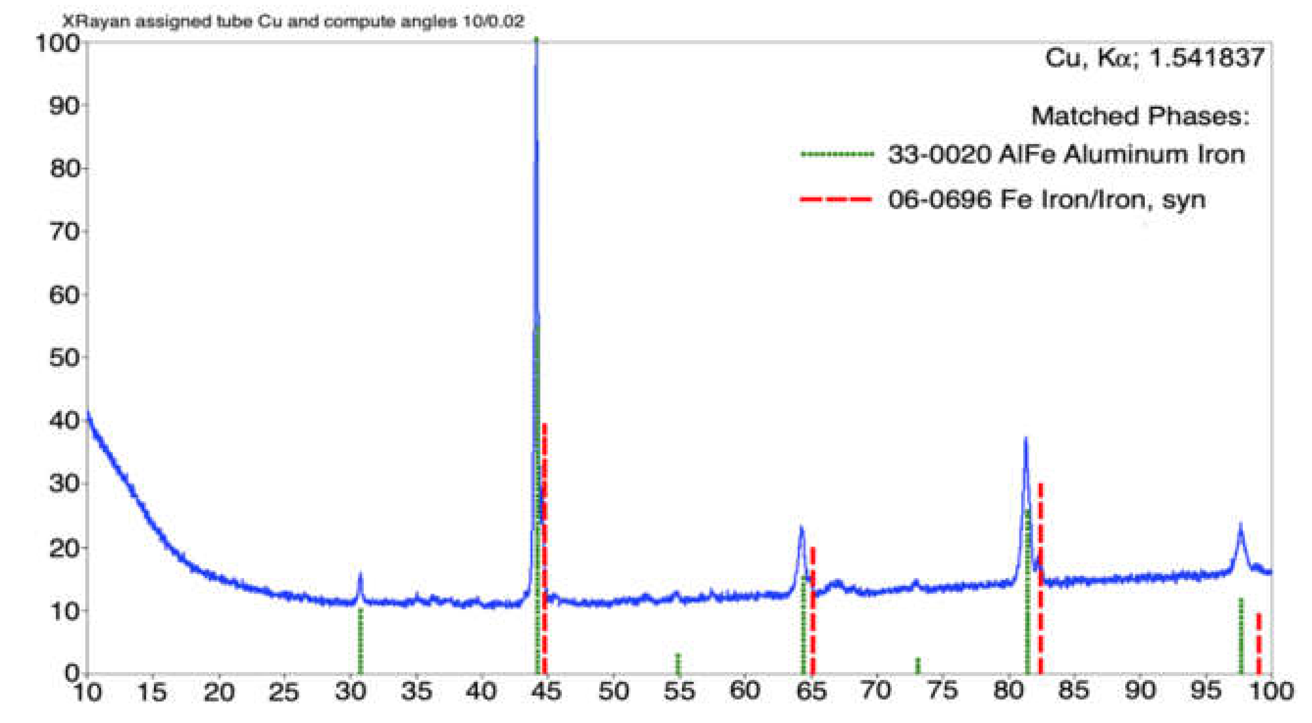
3.3. XRD Analysis
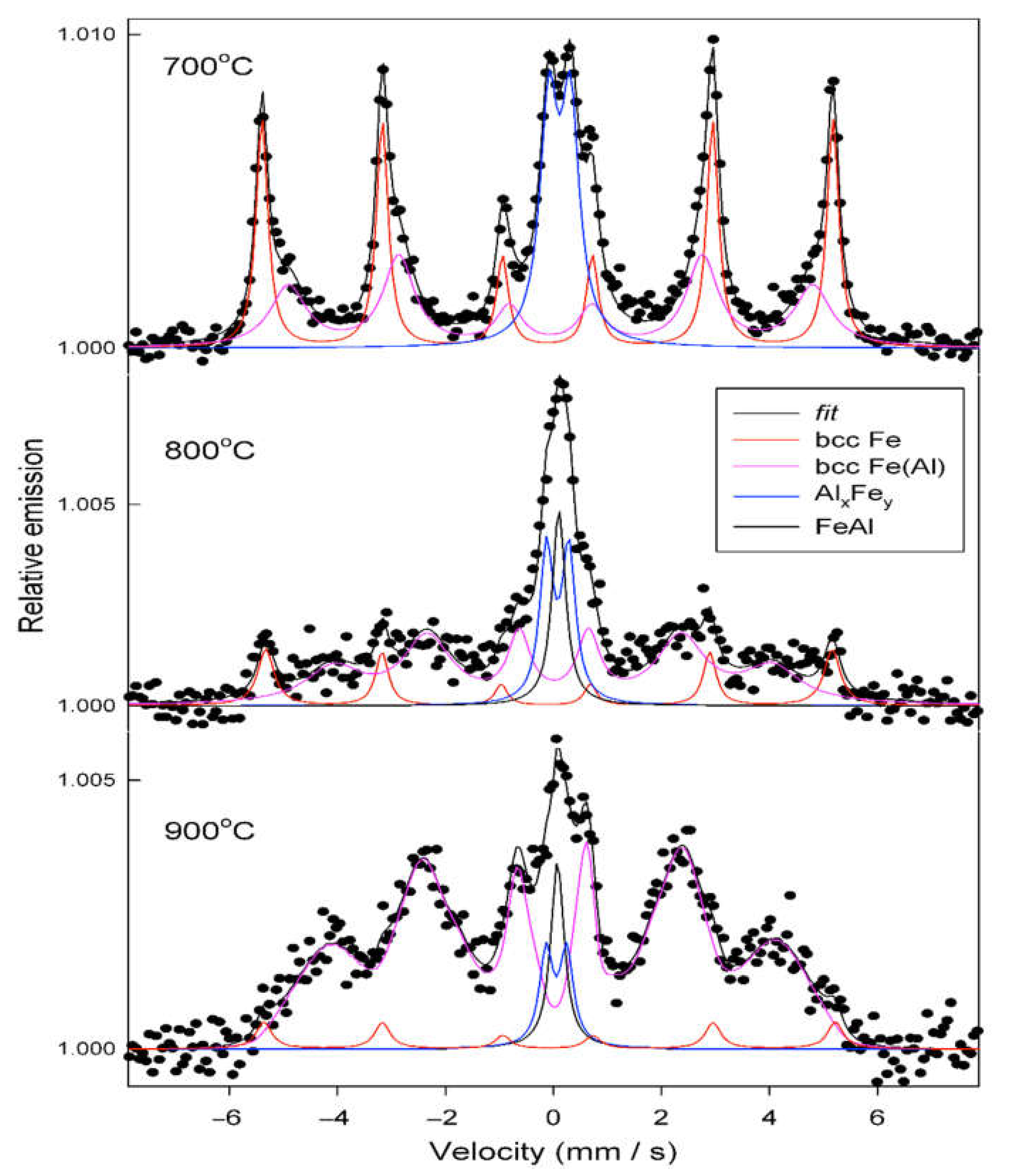
3.4. Mössbauer Spectroscopy Results of Annealed Coatings
- A magnetically split component (sextet) with the hyperfine field of 32.7 T, assigned to bcc Fe atomic environments without Al atoms as the nearest neighbors; however, some Al atoms were present in the remote vicinity of Fe atoms, thus causing a reduction of the hyperfine field of 32.95 T, characteristic for the pure bcc Fe phase [10,48,49];
- A sextet with broad lines and average hyperfine field values in the range of 25−30 T, originating from bcc Fe(Al) disordered solid solution;
- A quadrupole doublet with the quadrupole splitting of 0.40−0.44 mm/s and the isomer shift ranging from 0.19 to 0.23 mm/s, assigned to a paramagnetic Al-rich AlxFey phase;
- A single line with the isomer shift of 0.22 mm/s, assigned to a paramagnetic intermetallic bcc FeAl phase.
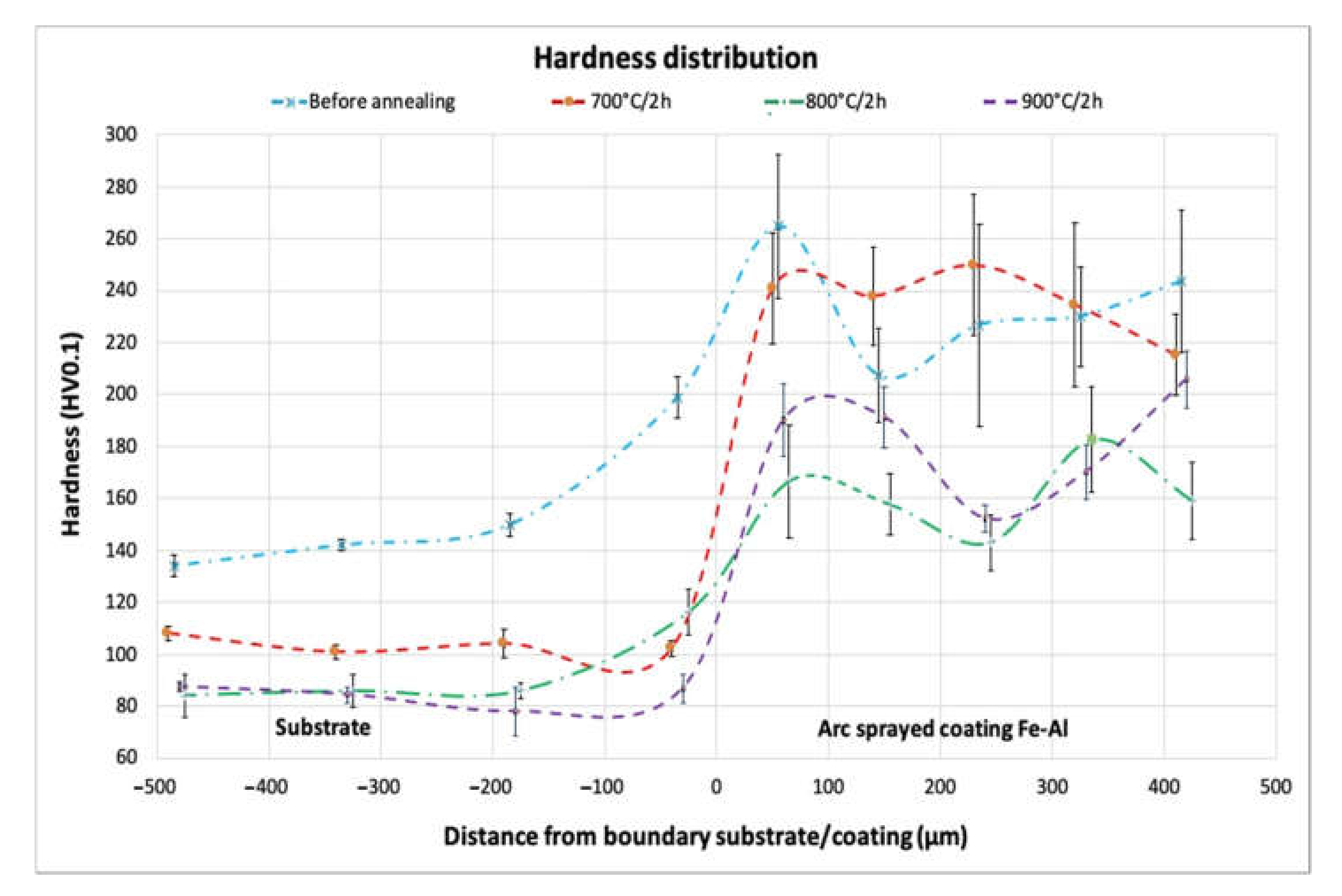
3.5. Hardness Analysis
4. Conclusions
- The composite arc-sprayed Fe-Al coating with initial low participation of in situ created intermetallic phases showed significant changes in the phase composition, with an increase in the volume fraction of Fe-Al intermetallic phases as a result of annealing;
- At the lower annealing temperature of 700 °C, besides the Fe(Al) solid solution, other transitional Al-rich Fe2Al5 intermetallic phases were formed;
- An increase in the heating temperature induced further diffusion of Al and the formation of different Fe-Al-type phases, namely, bcc Fe(Al) solid solution and disordered intermetallic FexAly phases with varying chemical compositions (according to the Fe-Al equilibrium system);
- The thermal activation at 800 °C and 900 °C for 2 h stimulated the formation of the FeAl intermetallic phase, with specific {100} reflection originating from a superlattice with B2 ordering (as confirmed in XRD investigations);
- A significant decrease of the bcc Fe metallic phase (from the range of 50% to about 5%) in the arc-sprayed Fe-Al coating was observed, with the increase of annealing temperature up to 900 °C/2 h;
- The volume fraction of the B2 ordered FeAl phase increased with increasing annealing temperature;
- After annealing at the temperature of 900 °C, the structure was composed of a B2 ordered FeAl intermetallic phase and disordered Fe3Al secondary solution, confirmed in the Mössbauer spectroscopy investigation;
- Heating of the arc-sprayed Fe-Al coating at a temperature of 900 °C for 2 h initiated the geometrical changes of lamellar structure, which ensured more homogeneity but was still not quite uniform in the SEM/EDX analysis;
- The microhardness distribution indicated significant differences in the hardness of the coatings after the annealing processes with three different temperature conditions;
- Annealing at temperatures of 800 °C and 900 °C caused a noticeable decrease in hardness;
- An additional effect was the reduction of the value of the standard deviation of the mean hardness value with the increase of the annealing temperature. The highest decrease in the value of the standard deviation from the mean hardness value occurred after annealing at the temperature of 900 °C, which confirmed the homogeneity changes of the structure.
Author Contributions
Funding
Institutional Review Board Statement
Informed Consent Statement
Data Availability Statement
Acknowledgments
Conflicts of Interest
References
- Zamanzade, M.; Barnoush, A.; Motz, H. A review on the properties of iron aluminide intermetallics. Crystals 2016, 6, 10. [Google Scholar] [CrossRef]
- Lisiecki, A.; Ślizak, D. Hybrid laser deposition of fe-based metallic powder under cryogenic conditions. Metals 2020, 10, 190. [Google Scholar] [CrossRef]
- Ye, H.; Peng, S.; Yan, Z.; Zhang, X. Microstructure and properties of laser cladding Fe-Al intermetallics. Adv. Mater. Res. 2013, 659, 39–42. [Google Scholar] [CrossRef]
- Wołczyński, W.; Senderowski, C.; Morgiel, J.; Garzeł, G. D-gun sprayed Fe-Al single particle solidification. Arch. Metall. Mater. 2014, 59, 211–220. [Google Scholar] [CrossRef]
- Pawłowski, A.; Senderowski, C.; Wołczyński, W.; Morgiel, J. Major Detonation deposited Fe-Al coatings Part II: Transmission electron microscopy of interlayers and Fe-Al intermetallic coating detonation sprayed onto the 045 steel substrate. Arch. Metall. Mater. 2011, 59, 211–220. [Google Scholar] [CrossRef]
- Pawłowski, A.; Czeppe, T.; Senderowski, C. Structure morphology of Fe-Al coating detonation sprayed onto carbon steel substrate. Arch. Metall. Mater. 2009, 54, 783–788. [Google Scholar]
- Górka, J.; Czupryński, A.; Zuk, M.; Adamiak, M.; Kopyść, A. Properties and structure of deposited nanocrystalline coatings in relation to selected construction materials resistant to abrasive wear. Materials 2018, 11, 1184. [Google Scholar] [CrossRef] [PubMed]
- Szczucka-Lasota, B.; Wegrzyn, T.; Stanik, Z.; Piwnik, J.; Sidun, P. Selected parameters of micro-jet cooling gases in hybrid spraying process. Arch. Metall. Mater. 2016, 61, 621–624. [Google Scholar] [CrossRef]
- Czupryński, A.; Gorka, J.; Adamiak, M. Examining properties of arc sprayed nanostructured coatings. Metalurgija 2016, 55, 173–176. [Google Scholar]
- Chmielewski, T.; Siwek, P.; Chmielewski, M.; Piątkowska, A.; Grabias, A.; Golański, D. Structure and selected properties of arc sprayed coatings containing in-situ fabricated Fe-Al intermetallic phases. Metals 2018, 8, 1059. [Google Scholar] [CrossRef]
- Xu, B.; Zhu, Z.; Ma, S.; Zhang, W.; Liu, W. Sliding wear behavior of Fe-Al and Fe-Al/WC coatings prepared by high velocity arc spraying. Wear 2004, 257, 1089–1095. [Google Scholar] [CrossRef]
- Cinca, N.; List, A.; Gärtner, F.; Guilemany, J.M. Influence of spraying parameters on cold gas spraying of iron aluminide intermetallics. Surf. Coat. Technol. 2015, 268, 99–107. [Google Scholar] [CrossRef]
- Bober, M. Composite coatings deposited by plasma transfer—Characteristics and formation. Weld. Int. 2015, 29, 946–950. [Google Scholar] [CrossRef]
- Cinca, N.; Guilemany, J.M. Thermal spraying of transition metal aluminides: An overview. Intermetallics 2012, 24, 60–72. [Google Scholar] [CrossRef]
- Shishkovsky, I.V. Laser-controlled intermetallics synthesis during surface cladding. In Laser Surface Engineering: Processes and Applications; Woodhead Publishing: Sawston, UK, 2015; pp. 237–286. ISBN 9781782420798. [Google Scholar]
- Nordmann, J.; Thiem, P.; Cinca, N.; Naumenko, K.; Kruger, M. Analysis of iron aluminide coated beams under creep conditions in high-temperature four-point bending tests. J. Strain Anal. Eng. Des. 2018, 53, 255–265. [Google Scholar] [CrossRef]
- Doleker, K.M. The Examination of Microstructure and Thermal Oxidation Behavior of Laser-Remelted High-Velocity Oxygen Liquid Fuel Fe/Al Coating. J. Mater. Eng. Perform. 2020, 29, 3220–3232. [Google Scholar] [CrossRef]
- Jozwik, P.; Bojar, Z.; Kołodziejczak, P. Microjoining of Ni3Al based intermetallic thin foils. Mater. Sci. Technol. 2010, 26, 473–477. [Google Scholar] [CrossRef]
- Guilemany, J.M.; Cinca, N.; Fernández, J.; Sampath, S. Erosion, abrasive, and friction wear behavior of iron aluminide coatings sprayed by HVOF. J. Therm. Spray Technol. 2008, 17, 762–773. [Google Scholar] [CrossRef]
- Szala, M.; Hejwowski, T. Zwiększanie odporności kawitacyjnej stopów metali przez napawanie powłok. Weld. Technol. Rev. 2015, 87, 57–60. [Google Scholar] [CrossRef][Green Version]
- Szala, M.; Walczak, M.; Pasierbiewicz, K.; Kamiński, M. Cavitation erosion and slidingwear mechanisms of AlTiN and TiAlN films deposited on stainless steel substrate. Coatings 2019, 9, 340. [Google Scholar] [CrossRef]
- Chmielewski, T.; Hudycz, M.; Krajewski, A.; Salaciński, T.; Skowrońska, B.; Świercz, R. Structure investigation of titanium metallization coating deposited onto AlN ceramics substrate by means of friction surfacing process. Coatings 2019, 9, 845. [Google Scholar] [CrossRef]
- Tomków, J.; Rogalski, G.; Fydrych, D.; Labanowski, J. Advantages of the application of the temper bead welding technique during wet welding. Materials 2019, 16, 915. [Google Scholar] [CrossRef]
- Rajasekaran, R.; Lakshminarayanan, A.K.; Vasudevan, M.; Vasantharaja, P. Role of welding processes on microstructure and mechanical properties of nuclear grade stainless steel joints. Proc. Inst. Mech. Eng. Part L J. Mater. Des. Appl. 2019, 233, 2335–2351. [Google Scholar] [CrossRef]
- Adamiak, M.; Górka, J.; Kik, T. Structure analysis of welded joints of wear resistant plate and constructional steel. Arch. Mater. Sci. Eng. 2010, 46, 108–114. [Google Scholar]
- Tomków, J.; Fydrych, D.; Rogalski, G. Role of bead sequence in underwaterwelding. Materials 2019, 12, 3372. [Google Scholar] [CrossRef]
- Wołosz, K.J.; Wernik, J. On the heat in the nozzle of the industrial pneumatic pulsator. Acta Mech. 2016, 227, 1111–1122. [Google Scholar] [CrossRef]
- Senderowski, C.; Cinca, N.; Dosta, S.; Cano, I.G.; Guilemany, J.M. The Effect of Hot Treatment on Composition and Microstructure of HVOF Iron Aluminide Coatings in Na2SO4 Molten Salts. J. Therm. Spray Technol. 2019, 28, 1492–1510. [Google Scholar] [CrossRef]
- Wernik, J.; Wolosz, K.J. Study of heat transfer in fins of pneumatic pulsator using thermal imaging. Chem. Eng. Trans. 2015, 45, 985–990. [Google Scholar] [CrossRef]
- Hodulova, E.; Ramos, A.S.; Kolenak, R.; Kostolny, I.; Simekova, B.; Kovarikova, I. Characterization of ultrasonic soldering of Ti and Ni with Ni/Al reactive multilayer deposition. Weld. Technol. Rev. 2019, 91, 51–57. [Google Scholar] [CrossRef]
- Hong, L.; Xuan, L.; Haixin, H. Microstructure and properties of ZrO2 ceramic and Ti-6A-4V alloy vacuum brazed by Ti-28Ni filler metal. Weld. Technol. Rev. 2019, 91, 35–41. [Google Scholar] [CrossRef]
- Shishkovsky, I.; Missemer, F.; Kakovkina, N.; Smurov, I. Intermetallics synthesis in the Fe-Al system via layer by layer 3D laser cladding. Crystals 2013, 3, 517–529. [Google Scholar] [CrossRef]
- Sun, K.; Cheng, J.; Liu, X.; Fang, L.; Ma, L. In-Situ Fabrication of Fe–Al Intermetallic Coating by Laser Remelting. J. Mechatron. 2014. [Google Scholar] [CrossRef]
- Ma, H.; Ren, K.; Xiao, X.; Qiu, R.; Shi, H. Growth characterization of intermetallic compounds at the Cu/Al solid state interface. Mater. Res. Express 2019, 6, 1–11. [Google Scholar] [CrossRef]
- Chu, Y.J.; Li, X.Q.; Li, J.; Yang, F.; Yang, S.F. Effects of annealing temperature on microstructure and properties of AlFeCrCoNiTi high-entropy alloy coating prepared by laser cladding. Cailiao Rechuli Xuebao/Trans. Mater. Heat Treat. 2018. [Google Scholar] [CrossRef]
- Kik, T.; Moravec, J.; Novakova, I. New method of processing heat treatment experiments with numerical simulation support. In Proceedings of the IOP Conference Series: Materials Science and Engineering, Hong Kong, China, 12–14 December 2017; p. 227. [Google Scholar]
- Winczek, J.; Gawronska, E.; Gucwa, M.; Sczygiol, N. Theoretical and experimental investigation of temperature and phase transformation during SAW overlaying. Appl. Sci. 2019, 9, 1472. [Google Scholar] [CrossRef]
- Deevi, S.C.; Sikka, V.K. Nickel and iron aluminides: An overview on properties, processing, and applications. Intermetallics 1996, 4, 357–375. [Google Scholar] [CrossRef]
- Sun, Y.; Zhang, Z.; Jin, X.; Xu, B.; Zhao, G. Cutting force models for Fe–Al-based coating processed by a compound NC machine tool. Int. J. Adv. Manuf. Technol. 2015, 79, 693–704. [Google Scholar] [CrossRef]
- Cegan, T.; Petlak, D.; Skotnicova, K.; Jurica, J.; Smetana, B.; Zla, S. Metallurgical preparation of Nb-Al and W-Al intermetallic compounds and characterization of their microstructure and phase transformations by DTA technique. Molecules 2020, 25, 2001. [Google Scholar] [CrossRef]
- Spyra, J.; Michalak, M.; Niemiec, A.; Łatka, L.A. Mechanical properties investigations of the plasma sprayed coatings based on alumina powder. Weld. Technol. Rev. 2020, 92, 17–23. [Google Scholar] [CrossRef]
- Dean, S.W.; Potter, J.K.; Yetter, R.A.; Eden, T.J.; Champagne, V.; Trexler, M. Energetic intermetallic materials formed by cold spray. Intermetallics 2013, 43, 121–130. [Google Scholar] [CrossRef]
- Novák, P.; Michalcová, A.; Marek, I.; Mudrová, M.; Saksl, K.; Bednarčík, J.; Zikmund, P.; Vojtěch, D. On the formation of intermetallics in Fe-Al system—An in situ XRD study. Intermetallics 2013, 32, 127–136. [Google Scholar] [CrossRef]
- Wang, H.T.; Li, C.J.; Yang, G.J.; Li, C.X. Cold spraying of Fe/Al powder mixture: Coating characteristics and influence of heat treatment on the phase structure. Appl. Surf. Sci. 2008, 255, 2538–2544. [Google Scholar] [CrossRef]
- Naoi, D.; Kajihara, M. Growth behavior of Fe2Al5 during reactive diffusion between Fe and Al at solid-state temperatures. Mater. Sci. Eng. A 2007, 459, 375–382. [Google Scholar] [CrossRef]
- Pawlowski, L. Thermal Spraying Techniques. In The Science and Engineering of Thermal Spray Coatings; John Wiley & Sons: Hoboken, NJ, USA, 2008; pp. 67–113. [Google Scholar]
- Michalak, M.; Łatka, L.; Sokołowski, P.; Niemiec, A.; Ambroziak, A. The microstructure and selected mechanical properties of Al2O3 + 13 wt % TiO2 plasma sprayed coatings. Coatings 2020, 10, 173. [Google Scholar] [CrossRef]
- Perez Alcazar, G.A.; Galvao Da Silva, E. Mossbauer effect study of magnetic properties of Fe1-qAl q, 0. J. Phys. F Met. Phys. 1987, 17, 2323–2335. [Google Scholar] [CrossRef]
- Krasnowski, M.; Grabias, A.; Kulik, T. Phase transformations during mechanical alloying of Fe-50% Al and subsequent heating of the milling product. J. Alloys Compd. 2006, 424, 119–127. [Google Scholar] [CrossRef]
- Nasu, S.; Gonser, U.; Preston, R.S. Defects and phases of iron in aluminium. J. Phys. Colloq. 1980, 41, 385–386. [Google Scholar] [CrossRef]


| State of the Coating | Hardness Distribution, HV0.1 | ||||||||
| Approximately Distance from Boundary Substrate/Coating, μm | |||||||||
| −470 | −325 | −180 | −35 | 55 | 150 | 240 | 330 | 420 | |
| Before annealing | 134 | 142 | 149 | 198 | 264.75 | 207.25 | 226.75 | 230 | 243.5 |
| (7.91) | (4.3) | (8.32) | (15.99) | (55.36) | (36.31) | (77.82) | (38.22) | (54.55) | |
| 700 °C | 108 | 100.83 | 104.05 | 102.3 | 240.75 | 237.75 | 249.75 | 234.5 | 215.25 |
| (5.87) | (5.7) | (10.73) | (5.81) | (42.7) | (37.66) | (54.5) | (63.37) | (31.59) | |
| 800 °C | 84.03 | 85.75 | 85.85 | 116.4 | 166.5 | 157.5 | 143 | 182.5 | 159 |
| (16.46) | (12.53) | (5.85) | (17.82) | (43.87) | (23.69) | (21.44) | (40.6) | (29.67) | |
| 900 °C | 87.35 | 84.33 | 77.83 | 86.68 | 190 | 191.25 | 152.25 | 170 | 205 |
| (4.12) | (6.24) | (18.38) | (11.11) | (27.61) | (23.59) | (10.13) | (20.99) | (21.83) | |
Publisher’s Note: MDPI stays neutral with regard to jurisdictional claims in published maps and institutional affiliations. |
© 2021 by the authors. Licensee MDPI, Basel, Switzerland. This article is an open access article distributed under the terms and conditions of the Creative Commons Attribution (CC BY) license (https://creativecommons.org/licenses/by/4.0/).
Share and Cite
Chmielewski, T.; Chmielewski, M.; Piątkowska, A.; Grabias, A.; Skowrońska, B.; Siwek, P. Phase Structure Evolution of the Fe-Al Arc-Sprayed Coating Stimulated by Annealing. Materials 2021, 14, 3210. https://doi.org/10.3390/ma14123210
Chmielewski T, Chmielewski M, Piątkowska A, Grabias A, Skowrońska B, Siwek P. Phase Structure Evolution of the Fe-Al Arc-Sprayed Coating Stimulated by Annealing. Materials. 2021; 14(12):3210. https://doi.org/10.3390/ma14123210
Chicago/Turabian StyleChmielewski, Tomasz, Marcin Chmielewski, Anna Piątkowska, Agnieszka Grabias, Beata Skowrońska, and Piotr Siwek. 2021. "Phase Structure Evolution of the Fe-Al Arc-Sprayed Coating Stimulated by Annealing" Materials 14, no. 12: 3210. https://doi.org/10.3390/ma14123210
APA StyleChmielewski, T., Chmielewski, M., Piątkowska, A., Grabias, A., Skowrońska, B., & Siwek, P. (2021). Phase Structure Evolution of the Fe-Al Arc-Sprayed Coating Stimulated by Annealing. Materials, 14(12), 3210. https://doi.org/10.3390/ma14123210