
Printability and Setting Time of CSA Cement with Na2SiO3 and Gypsum for Binder Jetting 3D Printing


Abstract
1. Introduction
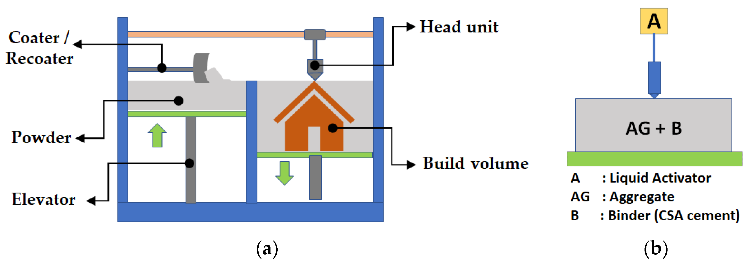
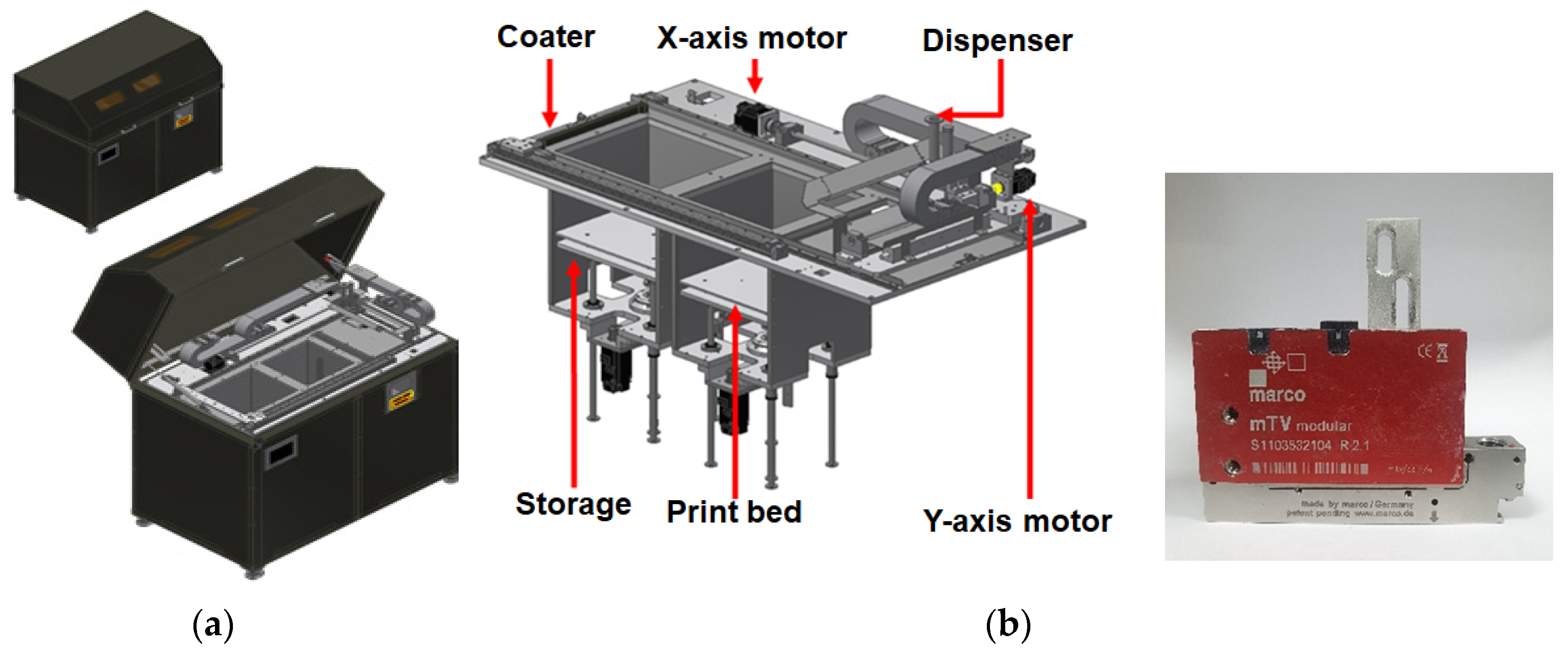
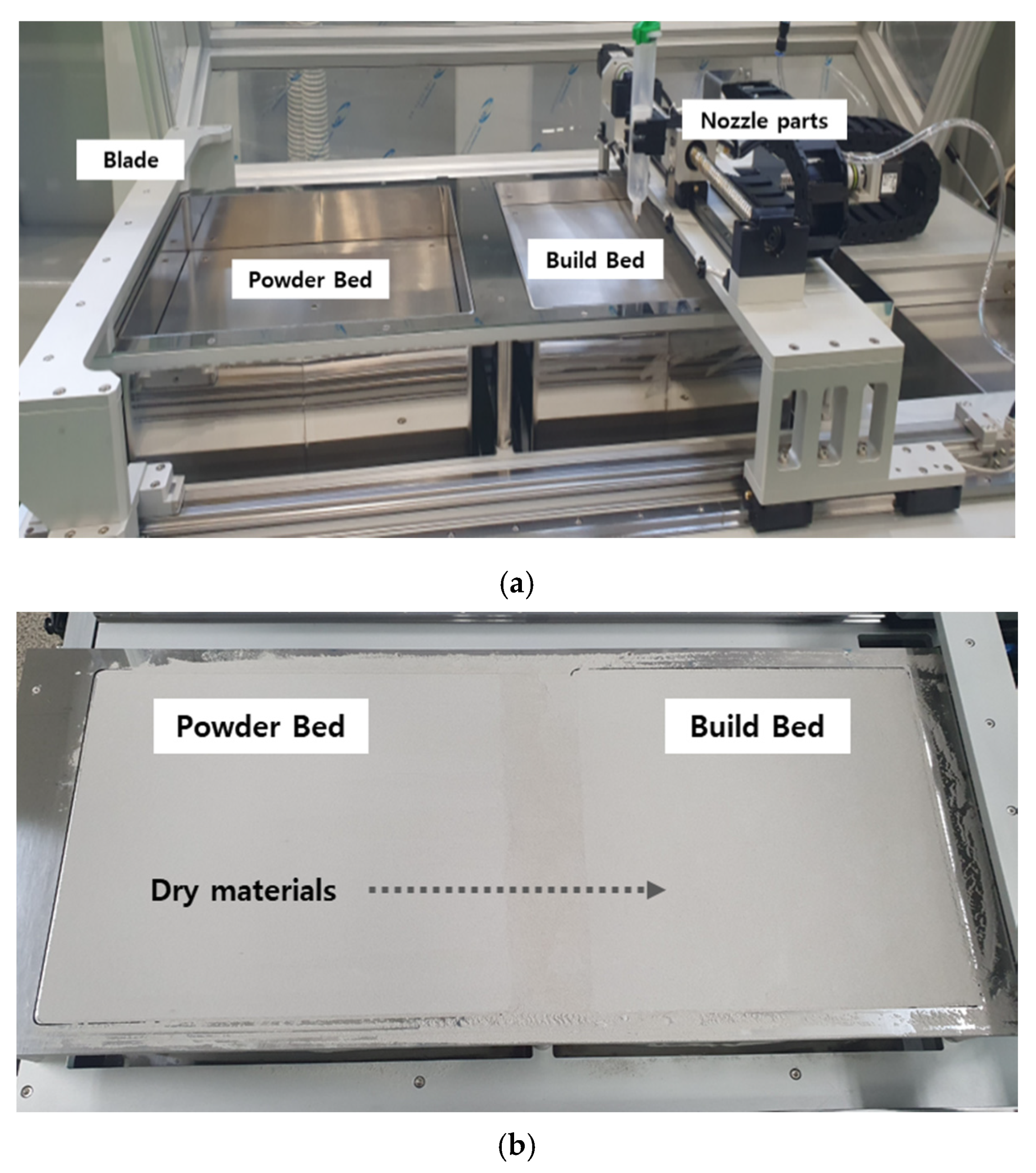
2. Configuration of Binder Jetting 3D Print
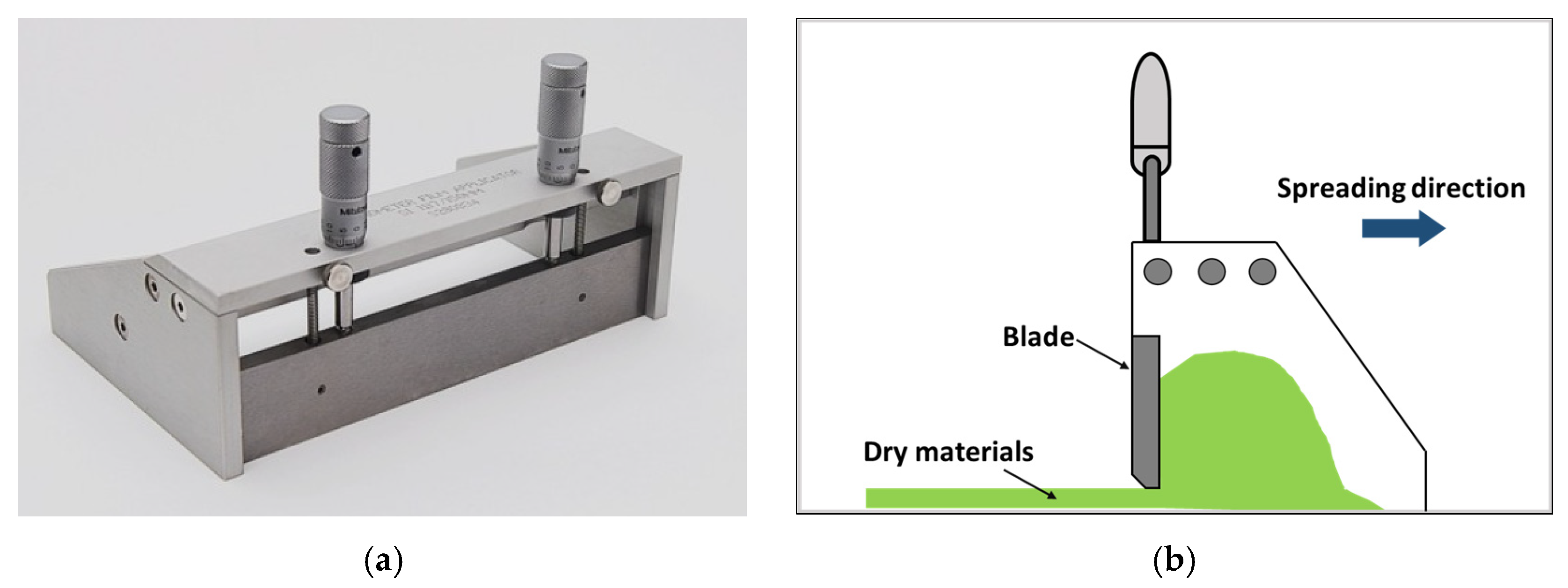
3. Preparation of Dry Materials and Verification Method of Printing Performance
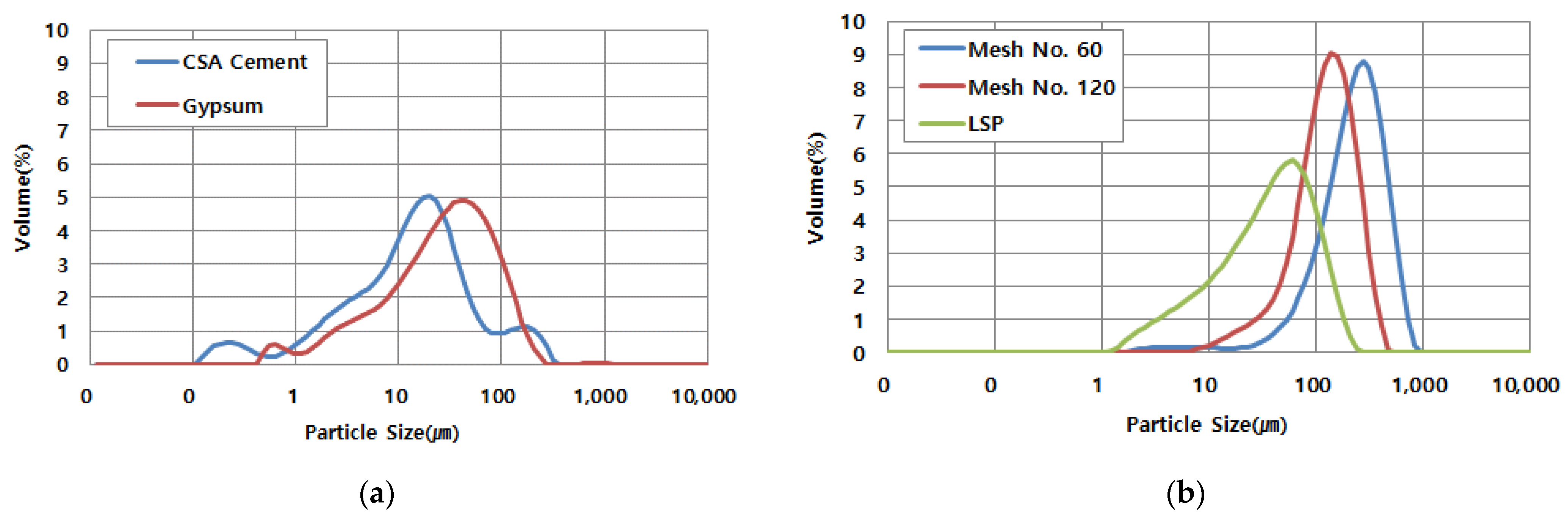
3.1. Dry Materials
3.2. Liquid Activator
4. Experimental Results and Discussion
4.1. Preliminary Test
4.2. Optimum Ratio of Dry Materials
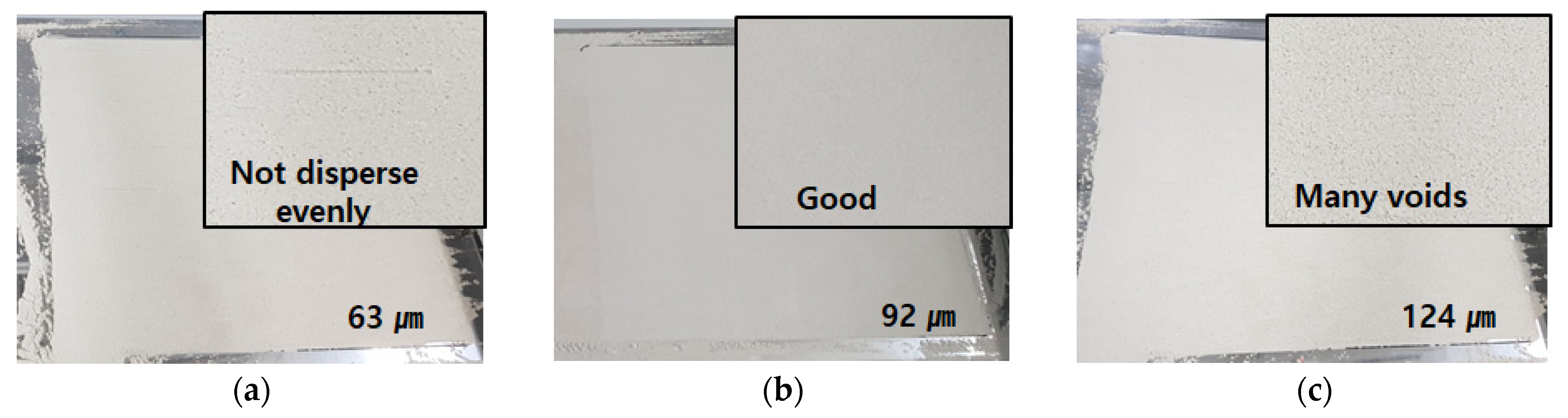
4.2.1. Dispersibility of CSA Cement and Sand
4.2.2. Setting Time Measurement of Dry Materials
4.3. Development of Binder
4.3.1. Optimum Ratio of Sodium Silicate (Na2SiO3) and Water
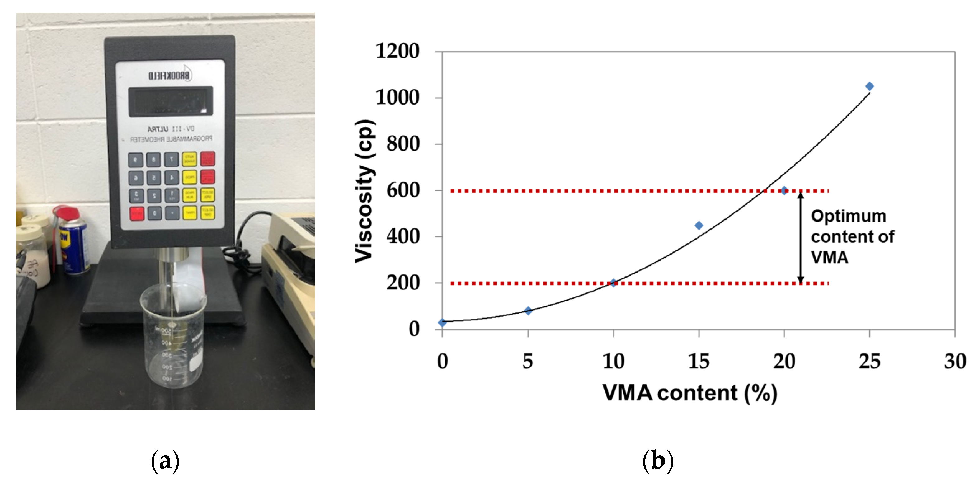
4.3.2. Optimum Content of Viscosity Modified Admixture (VMA)
4.4. Binder Jetting Printing Test with Optimum Dry materials and Binder
4.4.1. Viscosity Effect of the Liquid Activator
4.4.2. Effect of Setting Time
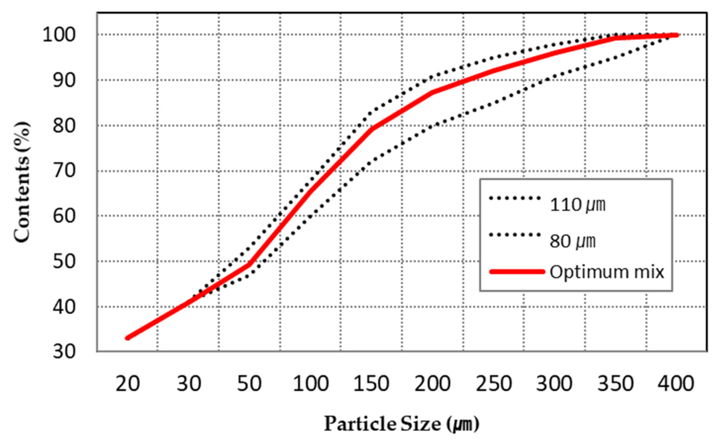
4.5. Optimum Mix Design for Binder Jet Printing
5. Conclusions
- The optimal mixture of dry materials and the liquid activator was derived through various parametric studies. For the dry materials, 40% of CSA cement, 10% of gypsum, and 50% of sand (No. 120) were suitable, and for the liquid activator, 35% of sodium silicate, 55% of water, and 10% of VMA were selected.
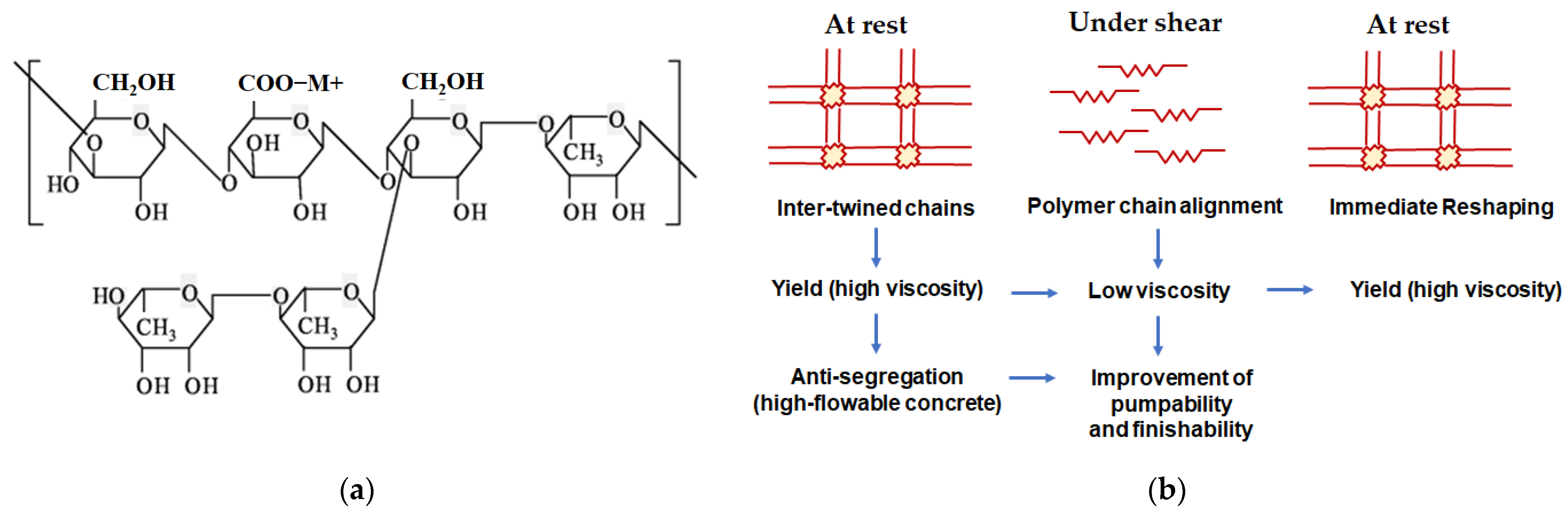
- The VMA in the liquid activator could have its properties changed sensitively depending on the temperature, but when used with 35% of sodium silicate solution, there was no problem printing with a viscosity of 200–400 cP.
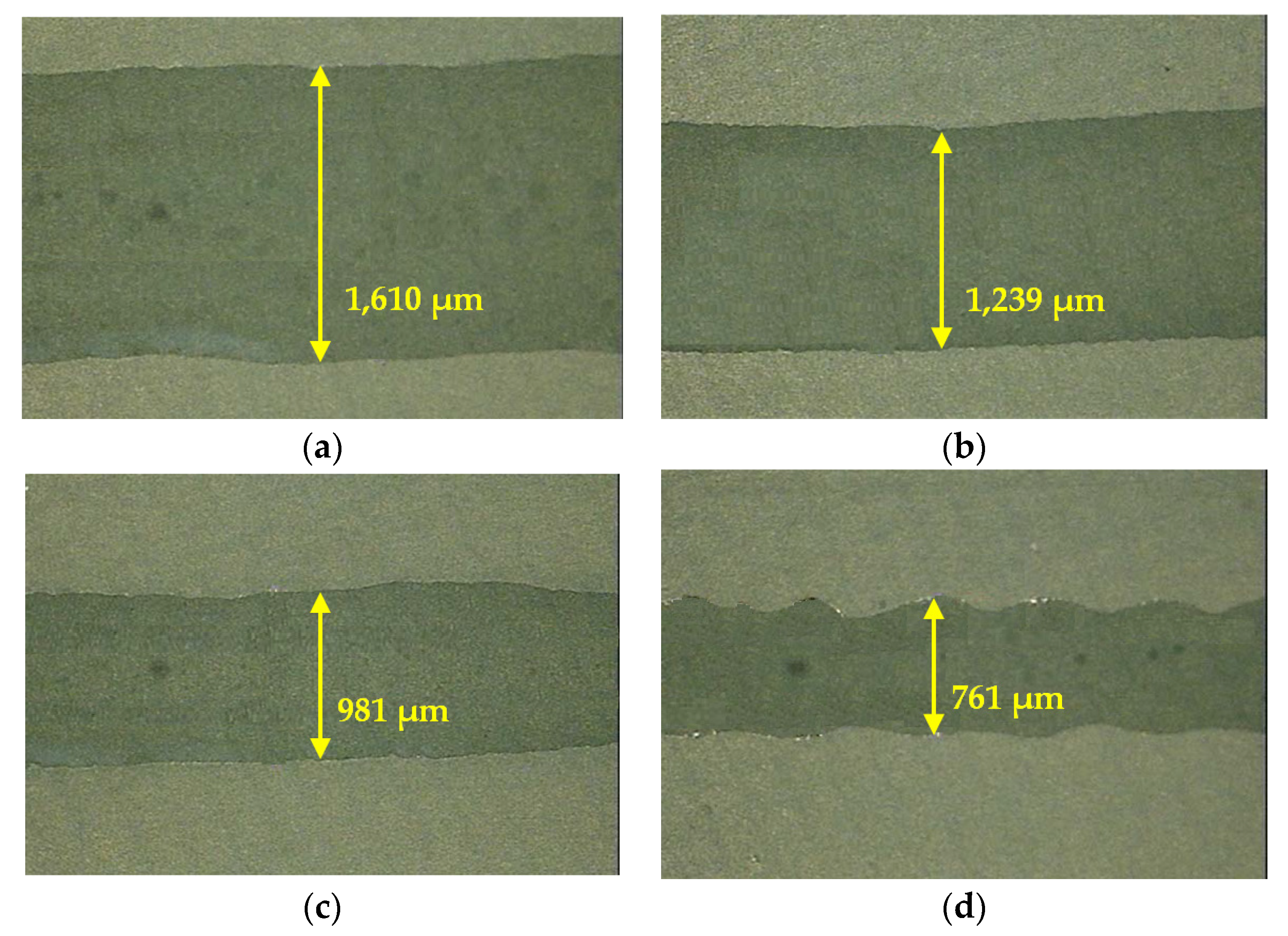
- The setting time with gypsum and sodium silicate was controlled within 30 s. In case of the delayed setting time, when printed, the jetting line was thickly printed and then the accuracy of the printout was degraded. In other words, the thickness of the jetting line in the output form was thicker than the desired shape. On the contrary, in case of the rapid setting mixture, when the amount of sodium silicate or gypsum was high, the hardening between dry materials and activator occurred quickly. As a result of the test, when the setting proceeded quickly, the thickness of the line became thinner and the nozzle was clogged because the dry materials and the liquid activator reacted immediately after contact with each other.
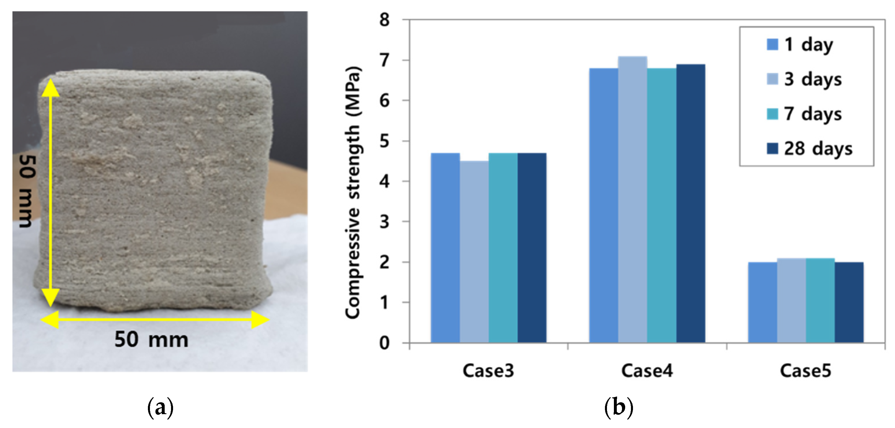
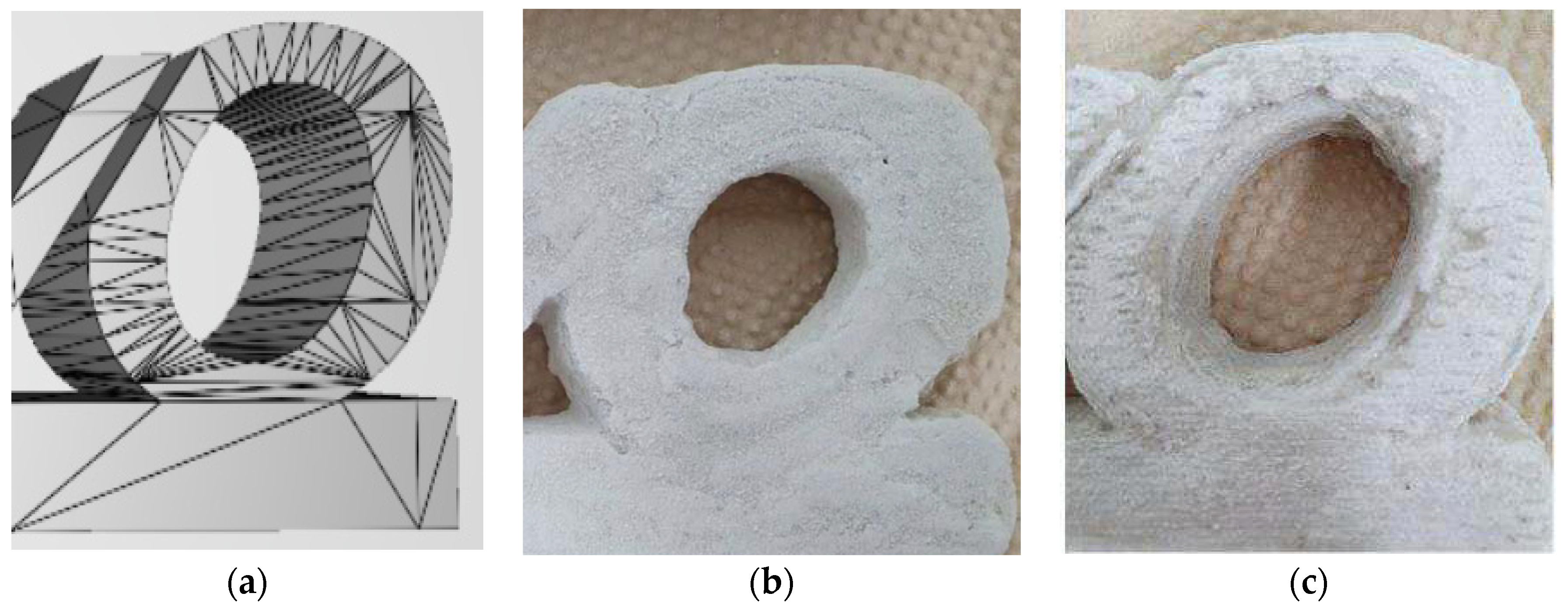
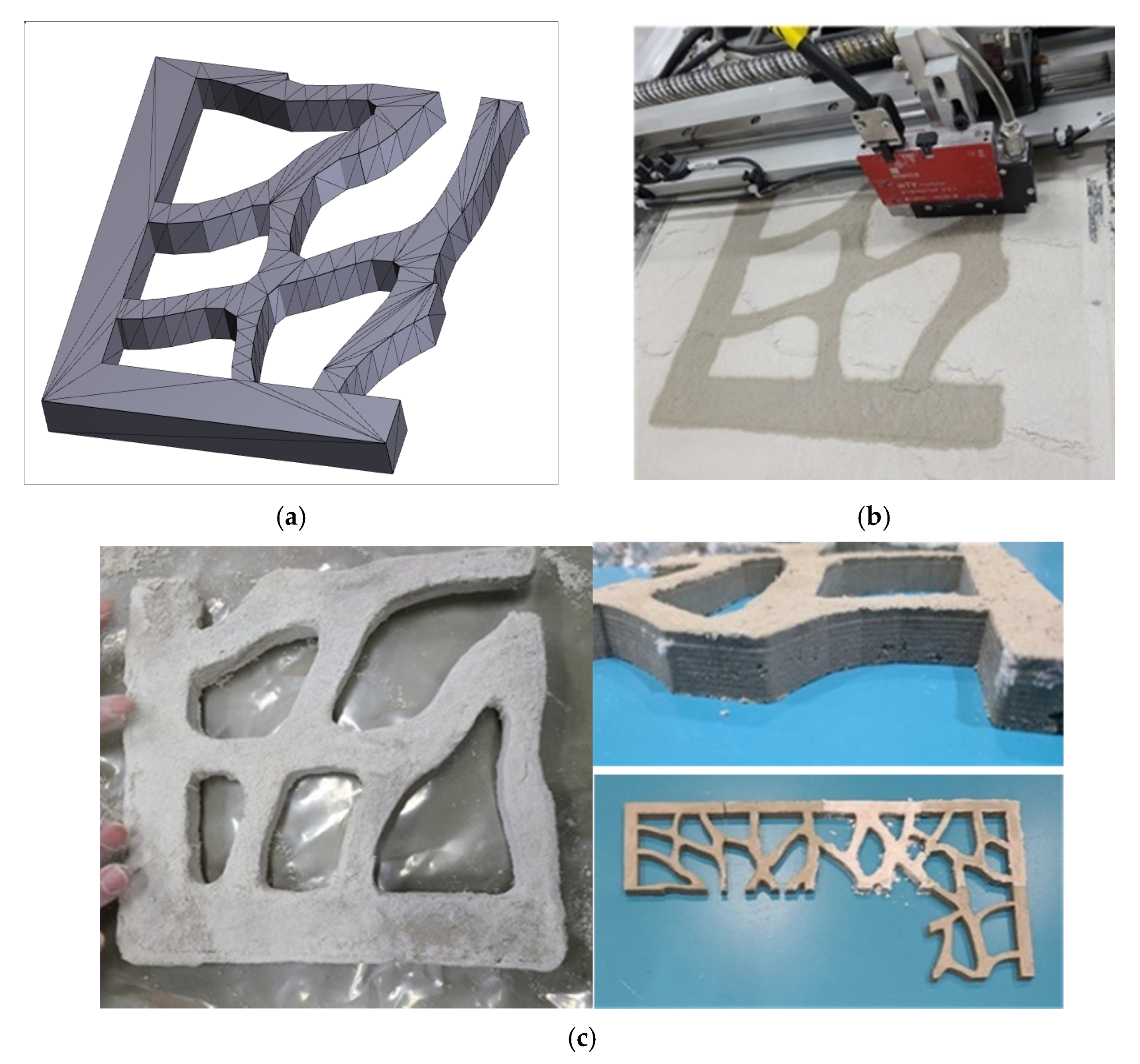
- A prototype of the atypical decorative element was printed, and the compressive strength was measured to be about 7 MPa. However, cracks were observed in some models after printing. Therefore, in future research, curing methods and post-treatment methods will be necessary. Additionally, the printing speed with current 3D printing equipment due to a single nozzle and the application to the field should be considered in terms of inkjet multiple nozzles.
Author Contributions
Funding
Institutional Review Board Statement
Informed Consent Statement
Data Availability Statement
Conflicts of Interest
References
- Lee, J.E.; Hong, G.H.; Choi, J.Y.; Jeon, S.M.; Kim, J.M. Investigation for Applying 3D Printing Technology to Housing Construction Process; Land & Housing Institute: Daejeon, Korea, 2015. [Google Scholar]
- Stahl, H. 3D Printing—Risks and Opportunities; Institute for Applied Energy: Freiburg, Germany, 2013. [Google Scholar]
- Yoo, S.K.; Park, H.S.; Bae, S.C. A Case Study of Domestic and Oversea Concrete 3D Printing Technology and Application. Mag. Korea Concr. Inst. 2019, 1, 58–64. [Google Scholar]
- Yoo, S.K. Case Study on Freeform Structure by Using 3D Printing Technology. Mag. Korea Concr. Inst. 2020, 7, 56–59. [Google Scholar]
- Seo, M.B.; Ju, G.B.; Shin, J.Y.; Jueng, S.M. Recent Research Trends in International and Domestic 3D Printing Construction. Mag. Korea Concr. Inst. 2020, 11, 28–33. [Google Scholar]
- Hong, D.H.; Ko, Y.H.; Park, K.W.; Kim, C.W.; Kim, G.T.; Choi, H.S. Development of 3D Printing Equipment for freeform Buildings. Mag. Korea Concr. Inst. 2020, 11, 40–46. [Google Scholar]
- Park, K.M.; Lee, J.; Lee, B.C. Improvement in Strength of 3D Printed Alkali-activated Slag/Fly ash Paste. J. Korea Concr. Inst. 2018, 30, 641–648. [Google Scholar] [CrossRef]
- ASTM F2792-12a. Standard Terminology for Additive Manufacturing Technologies; ASTM International: West Conshohocken, PA, USA, 2012; (Withdrawn 2015). [Google Scholar]
- Seo, J.S.; Lee, B.C.; Kim, Y.Y. Uniformity and Accuracy of Mortar Layer Thickness for the Quality Evaluation of 3D Printer Output. J. Korea Concr. Inst. 2020, 32, 371–377. [Google Scholar] [CrossRef]
- KATS Technical Report. Global Standardization Trends of 3D Printing; Korean Agency for Technology and Standards: Eumseong, Korea, 2016.
- Nematollahi, B.; Xia, M.; Sanjayan, J. Current Progress of 3D Concrete Printing Technologies. In ISARC, Proceedings of the International Symposium on Automation and Robotics in Construction; IAARC Publications: Taipei, Taiwan, 2017. [Google Scholar]
- Gosselin, C.; Duballet, R.; Roux, P.; Gaudillière, N.; Dirrenberger, J.; Morel, P. Large-scale 3D Printing of Ultra-high Performance Concrete–A New Processing Route for Architects and Builders. Mater. Des. 2016, 100, 102–109. [Google Scholar] [CrossRef]
- Lowke, D.; Dini, E.; Perrot, A.; Weger, D.; Gehlen, C.; Dillenburger, B. Particle-bed 3D printing in concrete construction-Possibilities and challenges. Cem. Concr. Res. 2018, 112, 50–65. [Google Scholar] [CrossRef]
- Ziaee, M.; Crane, N.B. Binder jetting: A review of process, materials, and methods. Addit. Manuf. 2019, 28, 781–801. [Google Scholar] [CrossRef]
- Mirzababaei, S.; Pasebani, S. A Review on Binder Jet Additive Manufacturing of 316L Stainless Steel. J. Manuf. Mater. Process. 2019, 3, 82. [Google Scholar] [CrossRef]
- Hwa, L.C.; Rajoo, S.; Noor, A.M.; Ahmad, N.; Uday, M.B. Recent advances in 3D printing of porous ceramics: A review. Curr. Opin. Solid State Mater. Sci. 2017, 21, 323–347. [Google Scholar] [CrossRef]
- Lv, X.; Ye, F.; Cheng, L.; Fan, S.; Liu, Y. Binder jetting of ceramics: Powders, binders, printing parameters, equipment, and post-treatment. Ceram. Int. 2019, 45, 12609–12624. [Google Scholar] [CrossRef]
- Choi, J.H.; Hwang, K.H.; Kim, U.S.; Lee, J.H.; Shim, K.B.; Kang, S.M.; Cho, W.S. Improving ceramic monolith properties in binder jetting 3D printing using glass frit binders. J. Ceram. Process. Res. 2019, 20, 547–555. [Google Scholar] [CrossRef]
- Xia, M.; Sanjayan, J. Method of formulating geopolymer for 3D printing for construction applications. Mater. Des. 2016, 110, 382–390. [Google Scholar] [CrossRef]
- Xia, M.; Sanjayan, J.G. Methods of enhancing strength of geopolymer produced from powder based 3D printing process. Mater. Lett. 2018, 227, 281–283. [Google Scholar] [CrossRef]
- Xia, M.; Nematollahi, B.; Sanjayan, J. Printability, accuracy and strength of geopolymer made using powder-based 3D printing for construction applications. Autom. Constr. 2019, 101, 179–189. [Google Scholar] [CrossRef]
- Shakor, P.; Sanjayan, J.; Nazari, A.; Nejadi, S. Modified 3D printed powder to cement-based material and mechanical properties of cement scaffold used in 3D printing. Constr. Build. Mater. 2017, 138, 398–409. [Google Scholar] [CrossRef]
- Shakor, P.; Nejadi, S.; Paul, G.; Sanjayan, J. Dimensional accuracy, flowability, wettability, and porosity in inkjet 3DP for gypsum and cement mortar materials. Autom. Constr. 2020, 110, 1–19. [Google Scholar] [CrossRef]
- Joseph, I. Material characteristics of binder jet 3D printed hydrated CSA cement with the addition of fine aggregates. Ph.D. Thesis, Lehigh University, Bethlehem, PA, USA, 2018. [Google Scholar]
- Ingaglio, J.; Fox, J.; Naito, C.J.; Bocchini, P. Material characteristics of binder jet 3D printed hydrated CSA cement with the addition of fine aggregates. Constr. Build. Mater. 2019, 206, 494–503. [Google Scholar] [CrossRef]
- Coppola, L.; Bellezze, T.; Belli, A.; Bignozzi, M.C.; Bolzoni, F.; Brenna, A.; Cabrini, M.; Candamano, S.; Bolzoni, F.; Brenna, A.; et al. Binders alternative to Portland cement and waste management for sustainable construction—Part 1. JABFM 2018, 16, 186–202. [Google Scholar] [CrossRef] [PubMed]
- Marco Home Page: Superior Jet Dispensing Valve—The Heart of the System. Available online: https://www.marco.de/index.php?page=article&id=9&back=https://www.marco.de/index.php?page=dispensing&language=en (accessed on 24 May 2021).
- Winnefeld, F.; Kaufmann, J. Concrete produced with calcium sulfoaluminate cement–A potential system for energy and heat storage. In Proceedings of the First Middle East Conference on Smart Monitoring, Assessment and Rehabilitation of Civil Structures (SMAR 2011), Dubai, United Arab Emirates, 8–10 February 2011; pp. 1–9. [Google Scholar]
- Pacheco-Torgal, F.; Ivanov, V.; Karak, N.; Jonkers, H. Biopolymers and Biotech Admixtures for Eco-Efficient Construction Materials; Woodhead Publishing: Sawston, UK; Cambridge, UK, 2016. [Google Scholar]
- Ara, A. Jeknavorian, Viscosity Modifying Admixtures. Available online: https://www.concreteconstruction.net/how-to/concrete-production-precast/viscosity-modifying-admixtures (accessed on 24 May 2021).


| Category | Description | Materials | |
|---|---|---|---|
| Extrusion method | Material extrusion (ME) | To extrude the filament materials from nozzle and deposit on the build plate layer by layer | Polymer, cementitious materials |
| Jetting method | Binder jetting (BJ) | To spread the powder materials thinly on the build plate and spray the liquid bonding agent on the layer | Polymer, metal, ceramic |
| Material jetting (MJ) | To dispense the droplets of photosensitive materials and to be solidified by lighting sources | Polymer, waxes | |
| Type of Dry Materials | Usage | Average Particle Size (µm) | Manufacturer | |
|---|---|---|---|---|
| Powders | CSA Cement 1 | Rapid setting-time | 28.34 | Kerneos Inc. (Chesapeake, VA, USA) |
| Gypsum | To control and accelerate the setting time of CSA cement | 40.79 | Sampyo Co. (Seoul, Korea) | |
| Fine aggregates | Mesh No. 60 | Use to adjust the grading of aggregate | 241.70 | Sampyo Co. (Seoul, Korea) |
| Mesh No. 120 | 132.95 | |||
| LSP 2 | 46.09 | |||
| Cases | Mixing Proportion (%) | Average Particle Size (µm) | Dispersibility | |||
|---|---|---|---|---|---|---|
| CSA Cement | No. 60 | No. 120 | LSP | |||
| 1-1 | 50 | 40 | 10 | - | 124 | Many voids |
| 1-2 | 50 | 30 | 20 | - | 113 | Observed Few voids |
| 1-3 | 50 | 20 | 30 | - | 102 | good |
| 1-4 | 50 | 10 | 40 | - | 92 | good |
| 1-5 | 50 | - | 50 | - | 81 | good |
| 1-6 | 50 | - | 40 | 10 | 72 | Not dispersed evenly |
| 1-7 | 50 | - | 30 | 20 | 63 | Not dispersed evenly |
| Cases | Material Proportion (%) | Setting Time of Stir Mixing | Setting Time of Simulator | Compressive Strength at 24 h (MPa) | |
|---|---|---|---|---|---|
| CSA Cement | Sand | ||||
| 2-1 | 20 | 80 | 5 min | 4 min | 0.5 |
| 2-2 | 40 | 60 | 3 min | 3 min | 0.5 |
| 2-3 | 50 | 50 | 3 min | 3 min | 1.0 |
| 2-4 | 60 | 40 | 3 min | 3 min | 0.7 |
| 2-5 | 70 | 30 | 3 min | 3 min | 0.8 |
| 2-6 | 80 | 20 | 2 min | 3 min | 0.7 |
| 2-7 | 100 | 0 | 2 min | 3 min | None |
| Cases | Material Proportion (%) | Setting Time of Stir Mixing | Setting Time of Simulator | Compressive Strength at 24 h (MPa) | ||
|---|---|---|---|---|---|---|
| CSA Cement | Gypsum | Sand | ||||
| 3-1 | 30 | 10 | 60 | 60 s | 60 s | 1.8 |
| 3-2 | 25 | 15 | 60 | Less than 30 s | Less than 30 s | 2.1 |
| 3-3 | 45 | 5 | 50 | 60 s | 60 s | 4.7 |
| 3-4 | 40 | 10 | 50 | Less than 30 s | Less than 30 s | 7.1 |
| 3-5 | 35 | 15 | 50 | Less than 30 s | Less than 30 s | 2.1 |
| 3-6 | 65 | 5 | 30 | Less than 30 s | 60 s | 2.0 |
| 3-7 | 60 | 10 | 30 | Less than 30 s | Less than 30 s | 0.9 |
| Cases | Material Proportion (%) | Setting Time of Stir Mixing | Setting Time of Simulator | |
|---|---|---|---|---|
| Sodium Silicate | Water | |||
| 4-1 | 20 | 80 | Less than 3 min | Less than 3 min |
| 4-2 | 30 | 70 | Less than 1 min | Less than 2 min |
| 4-3 | 40 | 60 | Less than 30 s | Less than 30 s |
| 4-4 | 50 | 50 | Less than 30 s | Less than 30 s |
| 4-5 | 60 | 40 | Less than 30 s | Less than 30 s |
| 4-6 | 70 | 30 | Less than 30 s | Less than 30 s |
| Cases | Material Proportion (%) | Viscosity (cP) | ||
|---|---|---|---|---|
| Sodium Silicate | Water | VMA | ||
| 5-1 | 35 | 65 | - | 30 |
| 5-2 | 60 | 5 | 80 | |
| 5-3 | 55 | 10 | 200 | |
| 5-4 | 50 | 15 | 450 | |
| 5-5 | 45 | 20 | 600 | |
| 5-6 | 40 | 25 | 1050 | |
Publisher’s Note: MDPI stays neutral with regard to jurisdictional claims in published maps and institutional affiliations. |
© 2021 by the authors. Licensee MDPI, Basel, Switzerland. This article is an open access article distributed under the terms and conditions of the Creative Commons Attribution (CC BY) license (https://creativecommons.org/licenses/by/4.0/).
Share and Cite
Na, O.; Kim, K.; Lee, H.; Lee, H. Printability and Setting Time of CSA Cement with Na2SiO3 and Gypsum for Binder Jetting 3D Printing. Materials 2021, 14, 2811. https://doi.org/10.3390/ma14112811
Na O, Kim K, Lee H, Lee H. Printability and Setting Time of CSA Cement with Na2SiO3 and Gypsum for Binder Jetting 3D Printing. Materials. 2021; 14(11):2811. https://doi.org/10.3390/ma14112811
Chicago/Turabian StyleNa, Okpin, Kangmin Kim, Hyunjoo Lee, and Hyunseung Lee. 2021. "Printability and Setting Time of CSA Cement with Na2SiO3 and Gypsum for Binder Jetting 3D Printing" Materials 14, no. 11: 2811. https://doi.org/10.3390/ma14112811
APA StyleNa, O., Kim, K., Lee, H., & Lee, H. (2021). Printability and Setting Time of CSA Cement with Na2SiO3 and Gypsum for Binder Jetting 3D Printing. Materials, 14(11), 2811. https://doi.org/10.3390/ma14112811