
Off-Axis Flexural Properties of Multiaxis 3D Basalt Fiber Preform/Cementitious Concretes: Experimental Study


Abstract
1. Introduction
2. Materials and Methods
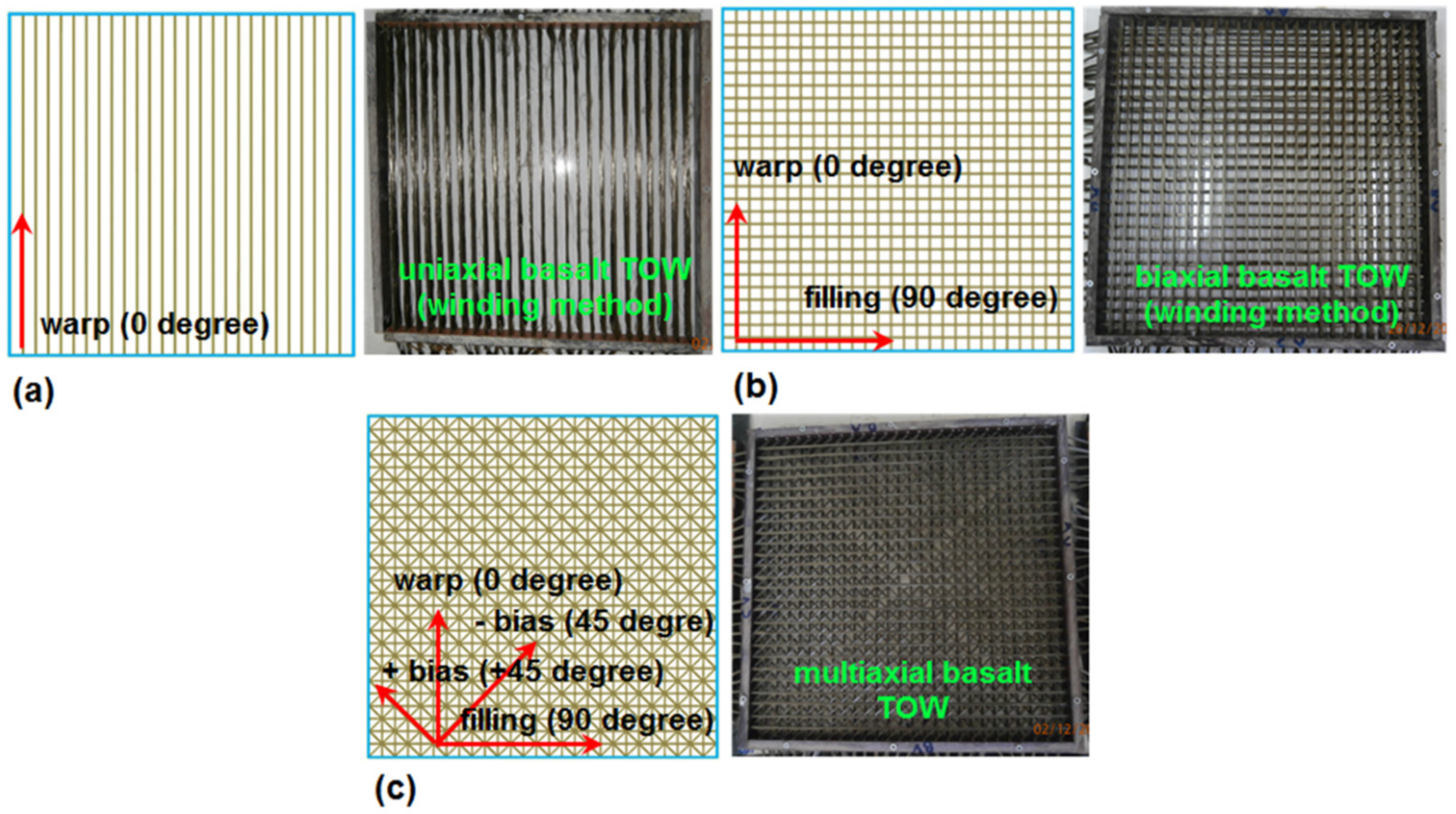
2.1. Multiaxis 3D Basalt Preforms and Basalt Concretes
2.2. Flexural Test for Multiaxis 3D Basalt Preform Concrete
3. Results and Discussion
3.1. Density and Fiber Volume Fraction Results
3.2. Flexural Test Results
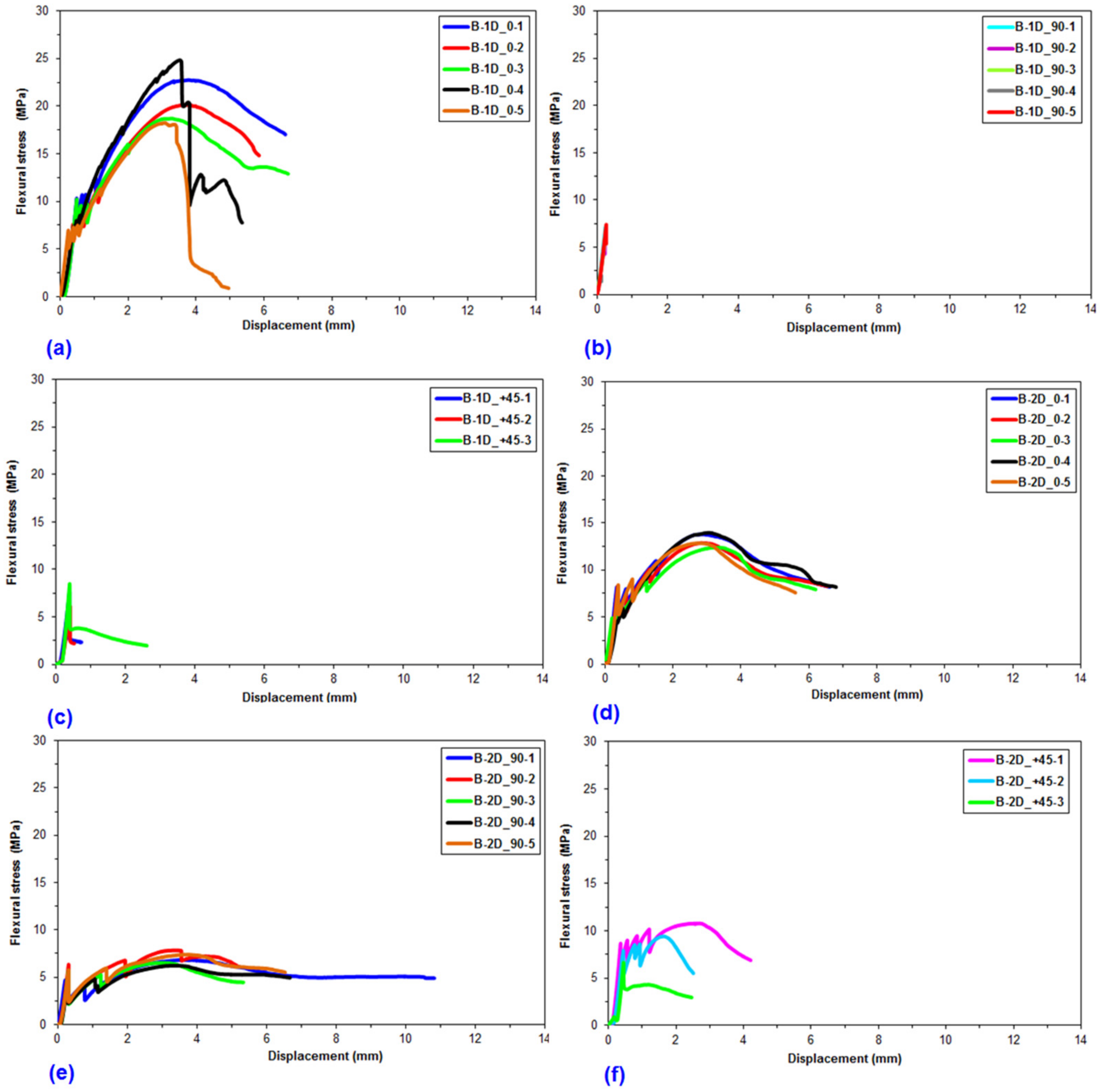
3.3. Flexural Load-Displacement
3.4. Flexural Strength
3.5. Off-Axis Flexural Energy
3.6. Off-Axis FTIR Analysis after Flexural Test
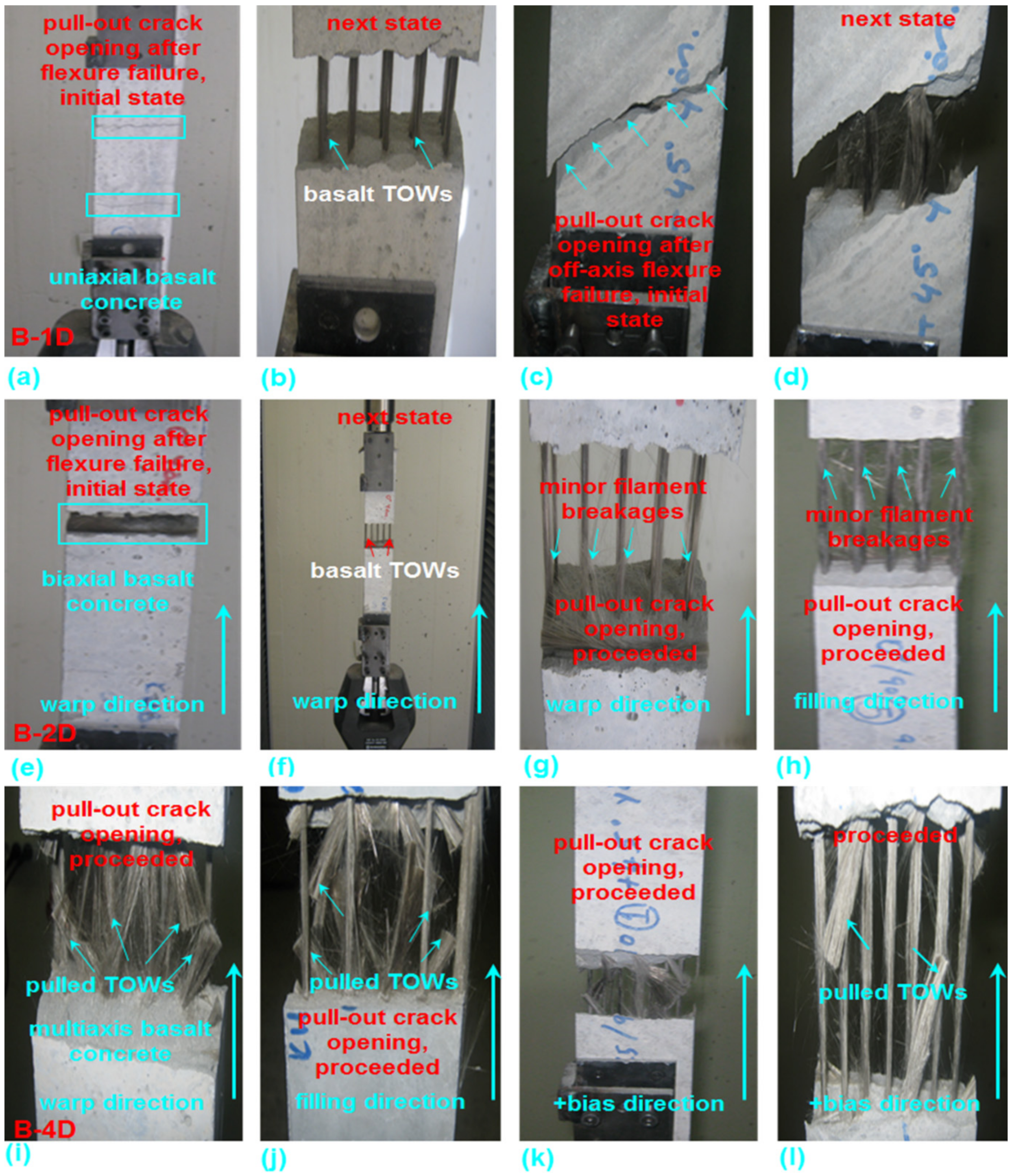
3.7. Flexural Failure Results
3.8. Flexural Failure Analysis
3.9. Failure Analysis by SEM Micrograph
4. Implementation of Research Outcome in Real-Life Projects
5. Conclusions
Author Contributions
Funding
Institutional Review Board Statement
Informed Consent Statement
Data Availability Statement
Acknowledgments
Conflicts of Interest
References
- Brameshuber, W. (Ed.) Textile Reinforced Concrete: State-of-the-Art Report of RILEM Technical Committee 201—TRC: Textile Reinforced Concrete; Report 36; RILEM: Bagneux, France, 2006; ISBN 2-912143-99-3. [Google Scholar]
- Hegger, J.; Will, N. Textile Reinforced Concrete: Proceedings of the 1st International RILEM Conference; Proceedings PRO 50; RILEM: Bagneux, France, 2006; ISBN 2-912143-97-7. [Google Scholar]
- Haubler-Combe, U.; Jesse, F.; Curbach, M. Textile reinforced concrete—Overview, experimental and theoretical investigations. In Fracture Mechanics of Concrete Structures. Proceedings of the Fifth International Conference on Fracture Mechanics of Concrete and Concrete Structures, Vail, CO, USA, 12–16 April 2004; Li, V.-C., Ed.; Ia-FraMCos: Bayonne, France, 2004; pp. 749–756. [Google Scholar]
- Bentur, A.; Mindess, S. Fibre Reinforced Cementitious Composites; Elsevier Applied Science: London, UK, 1990. [Google Scholar]
- Bilisik, K. Bending behavior of multilayered and multidirectional stitched aramid woven fabric structures. Text. Res. J. 2011, 81, 1748–1761. [Google Scholar] [CrossRef]
- Bilisik, K.; Karaduman, N.; Bilisik, N.-E. Fibrous and textile materials for composite applications. In Fibre Architectures for Composite Applications; Fangueiro, R., Rana, S., Eds.; Springer: Singapore, 2016; ISBN 978-981-10-0232-8. [Google Scholar]
- Wilkens, C. Warp Knitted Ware with Reinforcing Thread. US Patent 4518640, 1985. [Google Scholar]
- Bilisik, K. Three-dimensional axial braided preforms: Experimental determination of effects of structure-process parameters on unit cell. Text. Res. J. 2011, 81, 2095–2116. [Google Scholar] [CrossRef]
- Mukhopadhyay, S.; Khatana, S. A review on the use of fibers in reinforced cementitious concrete. J. Ind. Text. 2015, 45, 239–264. [Google Scholar] [CrossRef]
- Roye, A.; Gries, T. 3-D Textiles for Advanced Cement Based Matrix Reinforcement. J. Ind. Text. 2007, 37, 163–173. [Google Scholar] [CrossRef]
- Reinhardt, H.-W.; Kruger, M. Prestressed concrete plates with high strength fabrics. In Proceedings of the Sixth RILEM Symposium on Fiber-Reinforced Concrete (FRC, Paris, France), Verona, Italy, 20–22 September 2003; BEFIB: Collombey/Muraz, Switzerland, 2004; pp. 188–196. [Google Scholar]
- Reinhardt, H.W.; Krüger, M.; Große, C.U. Concrete Prestressed with Textile Fabric. J. Adv. Concr. Technol. 2003, 1, 231–239. [Google Scholar] [CrossRef]
- Quadflieg, T.; Leimbrink, S.; Gries, T.; Stolyarov, O. Effect of coating type on the mechanical performance of warp-knitted fabrics and cement-based composites. J. Compos. Mater. 2018, 52, 2563–2576. [Google Scholar] [CrossRef]
- Fangueiro, R. Fibrous and Composite Materials for Civil Engineering Applications; Woodhead Publishing: Cambridge, UK, 2011; pp. 62–89. [Google Scholar]
- Kargaran, A.; Kheyroddin, A. Experimental investigation of seismic strengthening of reinforced concrete short columns using externally bonded reinforcement, near surface mounted, and hybrid techniques. J. Compos. Mater. 2019, 54, 1177–1195. [Google Scholar] [CrossRef]
- Koutas, L.N.; Tetta, Z.; Bournas, D.A.; Triantafillou, T.C. Strengthening of Concrete Structures with Textile Reinforced Mortars: State-of-the-Art Review. J. Compos. Constr. 2019, 23, 03118001. [Google Scholar] [CrossRef]
- Peled, A.; Zhu, D.; Mobasher, B. High performance fiber reinforced cement composites. In Impact Behavior of 3D Fabric Reinforced Cementitious Composites; Parra-Montesinos, G.-J., Reinhardt, H.-W., Naaman, A.-E., Eds.; Springer: Berlin/Heidelberg, Germany, 2012; Volume 2. [Google Scholar]
- Li, V.C. Large volume, high-performance applications of fibers in civil engineering. J. Appl. Polym. Sci. 2001, 83, 660–686. [Google Scholar] [CrossRef]
- Coppola, B.; Maio, L.-D.; Courard, L.; Scarfato, P.; Incarnato, L. Nanocomposite fiber reinforced mortars. In Proceedings of the 22nd Annual International Conference on Composites/Nano Engineering (ICEE-22), La Valette, Malta, 13–19 July 2014; pp. 1–2. [Google Scholar]
- Aslani, F.; Wang, L.; Zheng, M. The effect of carbon nanofibers on fresh and mechanical properties of lightweight engineered cementitious composite using hollow glass microspheres. J. Compos. Mater. 2019, 53, 2447–2464. [Google Scholar] [CrossRef]
- Balea, A.; Fuente, E.; Monte, M.-C.; Blanco, A.; Negro, C. Fiber reinforced cement based composites. In Fibre Reinforced Composites: Constituents, Compatibility, Perspectives and Applications; Jospeh, K., Oksman, K., George, G., Wilson, R., Saritha, A., Eds.; Elsevier: Cambridge, UK, 2021; Volume 20, pp. 597–635. [Google Scholar]
- Xu, S.; Liu, J.; Li, Q. Mechanical properties and microstructure of multi-walled carbon nanotube-reinforced cement paste. Constr. Build. Mater. 2015, 76, 16–23. [Google Scholar] [CrossRef]
- Sanchez, F.; Sobolev, K. Nanotechnology in concrete—A review. Constr. Build. Mater. 2010, 24, 2060–2071. [Google Scholar] [CrossRef]
- Brik, V. Basalt Fiber Composite Reinforcement for Concrete; IDEA Project Final Report; Transportation Research Board, National Research Council: Washington, DC, USA, 1997. [Google Scholar]
- Brik, V. Advanced Concept Concrete Using Basalt Fiber/BF Composite Rebar Reinforcement; IDEA Project 86; Transportation Research Board, National Research Council: Washington, DC, USA, 2003. [Google Scholar]
- Tomlinson, D.; Fam, A. Performance of Concrete Beams Reinforced with Basalt FRP for Flexure and Shear. J. Compos. Constr. 2015, 19, 04014036. [Google Scholar] [CrossRef]
- Wu, J.; Li, H.; Xian, G. Influence of elevated temperature on the mechanical and thermal performance of BFRP rebar. In Proceedings of the 5th International Conference on FRP Composites in Civil Engineering (CICE 2010), Beijing, China, 27–29 September 2010; pp. 69–72. [Google Scholar]
- Shi, J.W.; Zhu, H.; Wu, Z.S.; Wu, G. Durability of BFRP and Hybrid FRP Sheets under Freeze-Thaw Cycling. Adv. Mater. Res. 2010, 163–167, 3297–3300. [Google Scholar] [CrossRef]
- Sim, J.; Park, C.; Moon, D.Y. Characteristics of basalt fiber as a strengthening material for concrete structures. Compos. Part B Eng. 2005, 36, 504–512. [Google Scholar] [CrossRef]
- Afroz, M.; Patnaikuni, I.; Venkatesan, S. Chemical durability and performance of modified basalt fiber in concrete medium. Constr. Build. Mater. 2017, 154, 191–203. [Google Scholar] [CrossRef]
- Ali, A.-H.-M.; Yu, W. Thermal protective performance of multilayer firefighting fabric. Int. J. Cloth. Sci. Technol. 2014, 26, 235–246. [Google Scholar]
- Hao, L.C.; Yu, W.D. Evaluation of thermal protective performance of basalt fiber nonwoven fabrics. J. Therm. Anal. Calorim. 2010, 100, 551–555. [Google Scholar] [CrossRef]
- Kašparová, M.; Wiener, J.; Shahidi, S. Multilayer assembly for protection against laser light. J. Text. Inst. 2019, 111, 226–234. [Google Scholar] [CrossRef]
- Quagliarini, E.; Monni, F.; Bondioli, F.; Lenci, S. Basalt fiber ropes and rods: Durability tests for their use in building engineering. J. Build. Eng. 2016, 5, 142–150. [Google Scholar] [CrossRef]
- Lv, Y.; Wu, X.; Gao, M.; Chen, J.; Zhu, Y.; Cheng, Q.; Chen, Y. Flexural Behavior of Basalt Fiber Reinforced Polymer Tube Confined Coconut Fiber Reinforced Concrete. Adv. Mater. Sci. Eng. 2019, 2019, 1–7. [Google Scholar] [CrossRef]
- Mousa, S.; Mohamed, H.M.; Benmokrane, B.; Ferrier, E. Flexural behavior of full-scale circular concrete members reinforced with basalt FRP bars and spirals: Tests and theoretical studies. Compos. Struct. 2018, 203, 217–232. [Google Scholar] [CrossRef]
- Henin, E.; Tawadrous, R.; Morcous, G. Effect of surface condition on the bond of Basalt Fiber-Reinforced Polymer bars in concrete. Constr. Build. Mater. 2019, 226, 449–458. [Google Scholar] [CrossRef]
- Shamassa, R.; Cashell, K.-A. Experimental investigation into the flexural behaviour of basalt FRP reinforced concrete members. Eng. Struct. 2020, 220, 1–16. [Google Scholar] [CrossRef]
- Daghash, S.M.; Ozbulut, O.E. Flexural performance evaluation of NSM basalt FRP-strengthened concrete beams using digital image correlation system. Compos. Struct. 2017, 176, 748–756. [Google Scholar] [CrossRef]
- Duic, J.; Kenno, S.; Das, S. Performance of concrete beams reinforced with basalt fibre composite rebar. Constr. Build. Mater. 2018, 176, 470–481. [Google Scholar] [CrossRef]
- Ovitigala, B.T.; Ibrahim, M.A.; Issa, M.A. Serviceability and Ultimate Load Behavior of Concrete Beams Reinforced with Basalt Fiber-Reinforced Polymer Bars. ACI Struct. J. 2016, 113, 113. [Google Scholar] [CrossRef]
- Attia, K.; Alnahhal, W.; Elrefai, A.; Rihan, Y. Flexural behavior of basalt fiber-reinforced concrete slab strips reinforced with BFRP and GFRP bars. Compos. Struct. 2019, 211, 1–12. [Google Scholar] [CrossRef]
- Branston, J.; Das, S.; Kenno, S.Y.; Taylor, C. Mechanical behaviour of basalt fibre reinforced concrete. Constr. Build. Mater. 2016, 124, 878–886. [Google Scholar] [CrossRef]
- High, C.; Seliem, H.M.; El-Safty, A.; Rizkalla, S.H. Use of basalt fibers for concrete structures. Constr. Build. Mater. 2015, 96, 37–46. [Google Scholar] [CrossRef]
- Abed, F.; AlHafiz, A.R. Effect of basalt fibers on the flexural behavior of concrete beams reinforced with BFRP bars. Compos. Struct. 2019, 215, 23–34. [Google Scholar] [CrossRef]
- Khanfour, M.-A.; Refai, A.-E. Effect of freeze-thaw cycles on concrete reinforced with basalt-fiber reinforced polymers (BFRP) bars. Constr. Build. Mater. 2017, 145, 135–146. [Google Scholar] [CrossRef]
- Lee, S.; Hong, K.; Yeon, Y.; Jung, K. Flexural Behavior of RC Slabs Strengthened in Flexure with Basalt Fabric-Reinforced Cementitious Matrix. Adv. Mater. Sci. Eng. 2018, 2018, 1–12. [Google Scholar] [CrossRef]
- Choobbor, S.S.; Hawileh, R.A.; Abu-Obeidah, A.; Abdalla, J.A. Performance of hybrid carbon and basalt FRP sheets in strengthening concrete beams in flexure. Compos. Struct. 2019, 227, 111337. [Google Scholar] [CrossRef]
- Kizilkanat, A.B.; Kabay, N.; Akyüncü, V.; Chowdhury, S.; Akça, A.H. Mechanical properties and fracture behavior of basalt and glass fiber reinforced concrete: An experimental study. Constr. Build. Mater. 2015, 100, 218–224. [Google Scholar] [CrossRef]
- Borhan, T.M. Properties of glass concrete reinforced with short basalt fibre. Mater. Des. 2012, 42, 265–271. [Google Scholar] [CrossRef]
- Fenu, L.; Forni, D.; Cadoni, E. Dynamic behaviour of cement mortars reinforced with glass and basalt fibres. Compos. Part B Eng. 2016, 92, 142–150. [Google Scholar] [CrossRef]
- Peled, A.; Bentur, A. Geometrical characteristics and efficiency of textile fabrics for reinforcing cement composites. Cem. Concr. Res. 2000, 30, 781–790. [Google Scholar] [CrossRef]
- Peled, A.; Bentur, A. Fabric structure and its reinforcing efficiency in textile reinforced cement composites. Compos. Part A Appl. Sci. Manuf. 2003, 34, 107–118. [Google Scholar] [CrossRef]
- Chi, H.-L.; Louda, P. Flexural performance evaluation of various carbon fibre fabric reinforced geopolymer composite. Ceramics-Silikáty 2020, 64, 215–226. [Google Scholar] [CrossRef]
- Kim, H.-Y.; You, Y.-J.; Ryu, G.-S.; Koh, K.-T.; Ahn, G.-H.; Kang, S.-H. Flexural Strengthening of Concrete Slab-Type Elements with Textile Reinforced Concrete. Materials 2020, 13, 2246. [Google Scholar] [CrossRef] [PubMed]
- Du, Y.; Zhang, X.; Zhou, F.; Zhu, D.; Zhang, M.; Pan, W. Flexural behavior of basalt textile-reinforced concrete. Constr. Build. Mater. 2018, 183, 7–21. [Google Scholar] [CrossRef]
- Wang, Q.; Yi, Y.; Ma, G.; Luo, H. Hybrid effects of steel fibers, basalt fibers and calcium sulfate on mechanical performance of PVA-ECC containing high-volume fly ash. Cem. Concr. Compos. 2019, 97, 357–368. [Google Scholar] [CrossRef]
- Liu, S.; Zhu, D.; Li, G.; Yao, Y.; Ou, Y.; Shi, C.; Du, Y. Flexural response of basalt textile reinforced concrete with pre-tension and short fibers under low-velocity impact loads. Constr. Build. Mater. 2018, 169, 859–876. [Google Scholar] [CrossRef]
- Ding, Y.; Wang, Q.; Pacheco-Torgal, F.; Zhang, Y. Hybrid effect of basalt fiber textile and macro polypropylene fiber on flexural load-bearing capacity and toughness of two-way concrete slabs. Constr. Build. Mater. 2020, 261, 119881. [Google Scholar] [CrossRef]
- Haque, M.A.; Chen, B.; Ahmad, M.R.; Shah, S.F.A. Mechanical strength and flexural parameters analysis of micro-steel, polyvinyl and basalt fibre reinforced magnesium phosphate cement mortars. Constr. Build. Mater. 2020, 235, 117447. [Google Scholar] [CrossRef]
- Smarzewski, P. Flexural toughness evaluation of basalt fibre reinforced HPC beams with and without initial notch. Compos. Struct. 2020, 235, 111769. [Google Scholar] [CrossRef]
- Alnahhal, W.; Aljidda, O. Flexural behavior of basalt fiber reinforced concrete beams with recycled concrete coarse aggregates. Constr. Build. Mater. 2018, 169, 165–178. [Google Scholar] [CrossRef]
- Rybin, V.; Utkin, A.; Baklanova, N. Alkali resistance, microstructural and mechanical performance of zirconia-coated basalt fibers. Cem. Concr. Res. 2013, 53, 1–8. [Google Scholar] [CrossRef]
- Li, M.; Gong, F.; Wu, Z. Study on mechanical properties of alkali-resistant basalt fiber reinforced concrete. Constr. Build. Mater. 2020, 245, 118424. [Google Scholar] [CrossRef]
- Wang, D.; Ju, Y.; Shen, H.; Xu, L. Mechanical properties of high performance concrete reinforced with basalt fiber and polypropylene fiber. Constr. Build. Mater. 2019, 197, 464–473. [Google Scholar] [CrossRef]
- Smarzewski, P. Influence of basalt-polypropylene fibres on fracture properties of high performance concrete. Compos. Struct. 2019, 209, 23–33. [Google Scholar] [CrossRef]
- Sun, X.; Gao, Z.; Cao, P.; Zhou, C.; Ling, Y.; Wang, X.; Zhao, Y.; Diao, M. Fracture performance and numerical simulation of basalt fiber concrete using three-point bending test on notched beam. Constr. Build. Mater. 2019, 225, 788–800. [Google Scholar] [CrossRef]
- Zhu, D.; Liu, S.; Yao, Y.; Li, G.; Du, Y.; Shi, C. Effects of short fiber and pre-tension on the tensile behavior of basalt textile reinforced concrete. Cem. Concr. Compos. 2019, 96, 33–45. [Google Scholar] [CrossRef]
- Brameshuber, W.; Brockmann, T.; Mobasher, B.; Pachow, U.; Peled, A.; Reinhardt, H.-W.; Krüger, M.; Wastiels, J. State of the art report of RILEM technical committee 201 TRC: Textile reinforced concrete. In Production Technologies; Brameshuber, W., Ed.; RILEM: Bagneux, France, 2006; pp. 57–81. [Google Scholar]
- Hegger, J.; Will, N.; Bentur, A.; Curbach, M.; Jesse, F.; Mobasher, B.; Peled, A.; Wastiels, J. State of the art report of RILEM technical committee 201 TRC: Textile reinforced concrete. In Mechanical Behavior of Textile Reinforced Concrete; Brameshuber, W., Ed.; RILEM: Bagneux, France, 2006; pp. 133–186. [Google Scholar]
- Yin, S.; Wang, B.; Wang, F.; Xu, S. Bond investigation of hybrid textile with self-compacting fine-grain concrete. J. Ind. Text. 2017, 46, 1616–1632. [Google Scholar] [CrossRef]
- Haik, R.; Sasi, E.A.; Peled, A. Influence of three-dimensional (3D) fabric orientation on flexural properties of cement-based composites. Cem. Concr. Compos. 2017, 80, 1–9. [Google Scholar] [CrossRef]
- Sasi, E.A.; Peled, A. Three dimensional (3D) fabrics as reinforcements for cement-based composites. Compos. Part A Appl. Sci. Manuf. 2015, 74, 153–165. [Google Scholar] [CrossRef]
- Jung, M.; Lee, Y.-S.; Hong, S.-G.; Moon, J. Carbon nanotubes (CNTs) in ultra-high performance concrete (UHPC): Dispersion, mechanical properties, and electromagnetic interference (EMI) shielding effectiveness (SE). Cem. Concr. Res. 2020, 131, 106017. [Google Scholar] [CrossRef]
- MacLeod, A.J.; Collins, F.G.; Duan, W.; Gates, W.P. Quantitative microstructural characterisation of Portland cement-carbon nanotube composites using electron and x-ray microscopy. Cem. Concr. Res. 2019, 123, 105767. [Google Scholar] [CrossRef]
- Meng, W.; Khayat, K.H. Effect of graphite nanoplatelets and carbon nanofibers on rheology, hydration, shrinkage, mechanical properties, and microstructure of UHPC. Cem. Concr. Res. 2018, 105, 64–71. [Google Scholar] [CrossRef]
- Balaguru, P.-N.; Shah, S.-P. High Performance Concretes and Applications; McGraw-Hill: New York, NY, USA, 1992. [Google Scholar]
- Shah, S.-P.; Swartz, S.-E.; Ouyang, C. Fracture Mechanics of Concrete: Applications of Fracture Mechanics to Concrete, Rock and Other Quasi-Brittle Materials; John Wiley & Sons: New York, NY, USA, 1995. [Google Scholar]
- Wecharatana, M.; Shah, S. A model for predicting fracture resistance of fiber reinforced concrete. Cem. Concr. Res. 1983, 13, 819–829. [Google Scholar] [CrossRef]
- Bilisik, K.; Ozdemir, H. Multiaxis three dimensional (3D) carbon and basalt preforms/cementitious matrix concretes: Experimental study on fiber orientation and placement by panel test. Constr. Build. Mater. 2021, 271, 121863. [Google Scholar] [CrossRef]
- Halvaei, M.; Jamshidi, M.; Latifi, M.; Ejtemaei, M. Effects of volume fraction and length of carbon short fibers on flexural properties of carbon textile reinforced engineered cementitious composites (ECCs); an experimental and computational study. Constr. Build. Mater. 2020, 245, 118394. [Google Scholar] [CrossRef]
- Zuo, J.-P.; Wang, X.-S.; Mao, D.-Q. SEM In Situ study on the effect of offset-notch on basalt cracking behavior under three-point bending load. Eng. Fract. Mech. 2014, 131, 504–513. [Google Scholar] [CrossRef]
- Mobasher, B.; Li, C.Y. Effect of interfacial properties on the crack propagation in cementitious composites. Adv. Cem. Based Mater. 1996, 4, 93–105. [Google Scholar] [CrossRef]
- Cai, J.; Pan, J.; Zhou, X. Flexural behavior of basalt FRP reinforced ECC and concrete beams. Constr. Build. Mater. 2017, 142, 423–430. [Google Scholar] [CrossRef]
- Liu, Z.; Worley II, R.; Du, F.; Giles, D.-D.; Dewoolkar, M.; Huston, D.; Tan, T. A study on avalanches of early age basalt fiber reinforced concrete beams during flexure. J. Clean. Prod. 2021, 279, 123695. [Google Scholar] [CrossRef]
- Cajka, R.; Marcalikova, Z.; Bilek, V.; Sucharda, O. Numerical Modeling and Analysis of Concrete Slabs in Interaction with Subsoil. Sustainability 2020, 12, 9868. [Google Scholar] [CrossRef]
- Basalt Roving. Available online: https://technobasalt.com/our-products/basalt-roving (accessed on 18 May 2020).
- Basifiber. Available online: https://basfiber.com/system/storage/download/Basalt_fiber_products_KV_SI.pdf (accessed on 20 June 2020).
- Bilisik, K.; Ozdemir, H. Multiaxis three-dimensional (3D) glass fiber preform/cementitious matrix concrete composites: Experimental characterizations by panel test. Cem. Concr. Compos. 2021, 119, 104020. [Google Scholar] [CrossRef]
- Naik, R.A. Failure Analysis of Woven and Braided Fabric Reinforced Composites. J. Compos. Mater. 1995, 29, 2334–2363. [Google Scholar] [CrossRef]
- Hahn, H.T.; Pandey, R. A Micromechanics Model for Thermoelastic Properties of Plain Weave Fabric Composites. J. Eng. Mater. Technol. 1994, 116, 517–523. [Google Scholar] [CrossRef]
- Chen, D.; Cheng, S. Analysis of composite materials: A micro-mechanical approach. J. Reinf. Plast. Compos. 1993, 12, 1323–1338. [Google Scholar] [CrossRef]
- Aljewifi, H.; Zhang, X.-B. Investigation on bond behavior of glass multifilaments yarn embedded in cementitious matrix. In Proceedings of the14th European Conference on Composite Materials, Budapest, Hungary, 7–10 June 2010. [Google Scholar]
- ASTM. ASTM, C 78/C78M-18. In Standard Test Method for Flexural Strength of Concrete; ASTM: West Conshohocken, PA, USA, 2018. [Google Scholar]
- ASTM. ASTM, C651-15. In Standard Test Method for Flexural Strength of Manufactured Carbon and Graphite Articles Using Four-Point Loading at Room Temperature; ASTM: West Conshohocken, PA, USA, 2015. [Google Scholar]
- ASTM. ASTM, C642-13. In Standard Test Method for Density, Absorption, and Voids in Hardened Concrete; ASTM: West Conshohocken, PA, USA, 2013. [Google Scholar]
- ASTM. ASTM, D3171-99. In Standard Test Methods for Constituent Content of Composite Materials; ASTM: West Conshohocken, PA, USA, 1999. [Google Scholar]
- Handy & Accurate Online Ruler. Available online: https://tr.piliapp.com/actual-size/cm-ruler/ (accessed on 18 July 2020).
- MATLAB R2016a; Simulink Design Optimization™, The MathWorks, Inc.: Natick, MA, USA, 2016.
- Mollah, M.; Yu, W.; Schennach, R.; Cocke, D.L. A Fourier transform infrared spectroscopic investigation of the early hydration of Portland cement and the influence of sodium lignosulfonate. Cem. Concr. Res. 2000, 30, 267–273. [Google Scholar] [CrossRef]
- Yılmaz, B.; Olgun, A. Studies on cement and mortar containing low-calcium fly ash, limestone, and dolomitic limestone. Cem. Concr. Compos. 2008, 30, 194–201. [Google Scholar] [CrossRef]
- Chang, C.-F.; Chen, J.-W. The experimental investigation of concrete carbonation depth. Cem. Concr. Res. 2006, 36, 1760–1767. [Google Scholar] [CrossRef]
- Tam, V.W.; Gao, X.; Tam, C. Microstructural analysis of recycled aggregate concrete produced from two-stage mixing approach. Cem. Concr. Res. 2005, 35, 1195–1203. [Google Scholar] [CrossRef]
- Deshmukh, G.S.; Peshwe, D.R.; Pathak, S.U.; Ekhe, J.D. A study on effect of mineral additions on the mechanical, thermal, and structural properties of poly(butylene terephthalate) (PBT) composites. J. Polym. Res. 2010, 18, 1081–1090. [Google Scholar] [CrossRef]
- Wu, Q.; Chi, K.; Wu, Y.; Lee, S. Mechanical, thermal expansion, and flammability properties of co-extruded wood polymer composites with basalt fiber reinforced shells. Mater. Des. 2014, 60, 334–342. [Google Scholar] [CrossRef]
- Zhang, Y.; Wang, X.; Wang, C.; Liu, J.; Zhai, H.; Liu, B.; Zhao, X.; Fang, D. Facile fabrication of zinc oxide coated superhydrophobic and superoleophilic meshes for efficient oil/water separation. RSC Adv. 2018, 8, 35150–35156. [Google Scholar] [CrossRef]
- Brown, V.; Bartholomew, C. Long-term deflections of GFRP-reinforced concrete beams. In Proceedings of the First International Conference on Composites in Infrastructure (ICCI-96), Tuscon, AZ, USA, 15–17 January 1996; pp. 389–400. [Google Scholar]


| Fiber | Fiber Diameter (μm) | Linear Density (tex) | Density (g/cm3) | Dry Fiber Tenacity (cN/tex) | Tensile Strength (MPa) | Tensile Modulus (GPa) | Breaking Elongation (%) | Melting Temperature (°C) |
|---|---|---|---|---|---|---|---|---|
| Basalt (technobasalt, UKR) | 16 | 4800 | 2.80 | 50–55 (1400–1540, MPa) | 2900 | 89 | 3.15 | 1450 |
| Type of Structure | Label | Fiber Type | Yarn Ends | Weave Type | Stacking Sequence/Number of Layers | Number of Twisting (Turn/m) | Plied Yarn (Tex) | Density of Preform (End/15 cm) | Mesh Opening (mm) |
|---|---|---|---|---|---|---|---|---|---|
| Control | CC | Concrete | - | - | - | - | - | - | - |
| Basalt concrete | B-1D-(0°) | Basalt | 4 | Non-interlaced | [0°]4 | 10 | 9600 | 10 | 15 |
| B-1D-(90°) | [90°]4 | ||||||||
| B-1D-(+45°) | [+45°]4 | ||||||||
| B-2D-(0°) | Basalt | 4 | Non-interlaced | [90°/0°]2 | 10 | 9600 | 10 | 15 × 15 | |
| B-2D-(90°) | [0°/90°]2 | ||||||||
| B-2D-(+45°) | [−45°/+45°]2 | ||||||||
| B-4D-(0°) | Basalt | 4 | Non-interlaced | [90°/±45°/0°]1 | 10 | 9600 | 10 | 15 × 15 ×15 × 15 | |
| B-4D-(90°) | [0°/±45°/90°]1 | ||||||||
| B-4D-(+45°) | [+45°/90°/0°/−45]1 | ||||||||
| B-4D-(−45°) | [+45°/0°/90°/−45]1 |
| Label | Density (kg/m3) | Total Fiber Weight Fractions (%) | Partial Fiber Weight Fraction (%) | Void Content (%) | Water Absorption (%) |
|---|---|---|---|---|---|
| CC | 2.190 | - | - | 22.080 | 11.160 |
| B-1D-(0°) | 2.170 | 3.830 | 3.830 (0°) | 18.045 | 8.735 |
| B-1D-(90°) | 2.170 | 3.830 | 3.830 (90°) | 18.045 | 8.735 |
| B-1D-(+45°) | 2.170 | 3.830 | 3.830 (+45°) | 18.045 | 8.735 |
| B-2D-(0°) | 2.210 | 3.760 | 1.880 (0°),1.880 (90°) | 18.855 | 9.490 |
| B-2D-(90°) | 2.210 | 3.760 | 1.880 (90°),1.880 (0°) | 18.855 | 9.490 |
| B-2D-(+45°) | 2.210 | 3.760 | 1.880 (+45°),1.880 (–45°) | 18.855 | 9.490 |
| B-4D-(0°) | 2.220 | 3.750 | 0.9375 (90°), 0.9375 (−45°), 0.9375 (+45°), 0.9375 (0°) | 19.935 | 10.060 |
| B-4D-(90°) | 2.220 | 3.750 | 0.9375 (0°), 0.9375 (+45°), 0.9375 (−45°), 0.9375 (90°) | 19.935 | 10.060 |
| B-4D-(+45°) | 2.220 | 3.750 | 0.9375 (+45°), 0.9375 (90°), 0.9375 (0°), 0.9375 (−45°) | 19.935 | 10.060 |
| B-4D-(−45°) | 2.220 | 3.750 | 0.9375 (+45°), 0.9375 (0°), 0.9375 (90°), 0.9375 (−45°) | 19.935 | 10.060 |
| Label | Flexural First Crack Load (N) | Flexural First Crack Displacement (mm) | Flexural Maximum Load (N) | Flexural Maximum Displacement (mm) | Flexural First Crack Strength (MPa) | Flexural Maximum Strength (MPa) | Flexural Stiffness (MPa/mm) |
|---|---|---|---|---|---|---|---|
| CC | 1374.93 ± 190.83 | 0.29 ± 0.07 | 1374.93 ± 190.83 | 0.29 ± 0.07 | 6.19 ± 0.86 | 6.19 ± 0.86 | 27.33 ± 1.08 |
| B-1D-(0°) | 1884.49 ± 325.94 | 0.40 ± 0.09 | 4646.59 ± 555.50 | 3.48 ± 0.27 | 8.49 ± 1.47 | 20.93 ± 2.50 | 23.46 ± 4.34 |
| B-1D-(90°) | 1281.43 ± 436.76 | 0.22 ± 0.05 | 1281.43 ± 436.76 | 0.22 ± 0.05 | 5.77 ± 1.97 | 5.77 ± 1.97 | 25.15 ± 5.36 |
| B-1D-(+45°) | 1645.00 ± 218.25 | 0.40 ± 0.00 | 1645.00 ± 218.25 | 0.40 ± 0.00 | 7.41 ± 0.99 | 7.41 ± 0.99 | 28.65 ± 4.80 |
| B-2D-(0°) | 1648.61 ± 239.04 | 0.42 ± 0.07 | 2923.85 ± 133.47 | 2.95 ± 0.19 | 7.42 ± 1.08 | 13.17 ± 0.60 | 24.74 ± 5.20 |
| B-2D-(90°) | 1170.53 ± 192.70 | 0.28 ± 0.04 | 1542.63 ± 131.39 | 3.44 ± 0.29 | 5.27 ± 0.87 | 6.95 ± 0.59 | 23.49 ± 1.77 |
| B-2D-(+45°) | 1715.52 ± 185.88 | 0.42 ± 0.04 | 1983.14 ± 382.57 | 1.58 ± 0.91 | 7.73 ± 0.84 | 8.93 ± 1.72 | 30.42 ± 2.86 |
| B-4D-(0°) | 1559.50 ± 227.30 | 0.45 ± 0.17 | 3352.22 ± 328.74 | 2.68 ± 0.22 | 7.02 ± 1.02 | 15.10 ± 1.48 | 21.99 ± 2.12 |
| B-4D-(90°) | 960.61 ± 239.17 | 0.30 ± 0.05 | 1092.53 ± 104.86 | 0.93 ± 0.98 | 4.33 ± 1.08 | 4.92 ± 0.47 | 20.54 ± 3.95 |
| B-4D-(+45°) | 1590.08 ± 57.20 | 0.39 ± 0.05 | 3007.62 ± 99.04 | 3.40 ± 0.04 | 7.16 ± 0.26 | 13.55 ± 0.45 | 24.50 ± 2.64 |
| B-4D-(−45°) | 1639.72 ± 202.78 | 0.39 ± 0.09 | 2840.53 ± 336.03 | 4.15 ± 0.45 | 7.38 ± 0.91 | 12.79 ± 1.52 | 20.10 ± 3.65 |
| Label | Flexural First Crack Energy (J) | Flexural Maximum Load Energy (J) | Flexural Strain-Hardening Energy (J) | Flexural Strain-Softening Energy (J) | Flexural Total Energy (J) |
|---|---|---|---|---|---|
| CC | 0.16 ± 0.05 | 0.16 ± 0.05 | 0.00 ± 0.00 | 0.01 ± 0.00 | 0.17 ± 0.05 |
| B-1D-(0°) | 0.26 ± 0.08 | 10.96 ± 1.87 | 10.70 ± 0.90 | 8.31 ± 1.44 | 19.27 ± 4.74 |
| B-1D-(90°) | 0.14 ± 0.06 | 0.14 ± 0.06 | 0.00 ± 0.00 | 0.00 ± 0.00 | 0.14 ± 0.06 |
| B-1D-(+45°) | 0.19 ± 0.02 | 0.19 ± 0.02 | 0.00 ± 0.00 | 0.00 ± 0.00 | 0.75 ± 0.63 |
| B-2D-(0°) | 0.29 ± 0.07 | 6.08 ± 0.37 | 5.79 ± 0.15 | 7.88 ± 0.48 | 13.96 ± 1.32 |
| B-2D-(90°) | 0.12 ± 0.03 | 3.92 ± 0.57 | 3.80 ± 0.27 | 4.43 ± 0.89 | 8.35 ± 2.35 |
| B-2D-(+45°) | 0.21 ± 0.03 | 2.54 ± 2.02 | 2.33 ± 1.00 | 2.08 ± 0.30 | 4.62 ± 2.61 |
| B-4D-(0°) | 0.22 ± 0.07 | 6.00 ± 0.76 | 5.78 ± 0.35 | 6.65 ± 0.14 | 12.65 ± 1.03 |
| B-4D-(90°) | 0.10 ± 0.03 | 0.61 ± 0.25 | 0.51 ± 0.11 | 6.23 ± 0.04 | 6.84 ± 0.32 |
| B-4D-(+45°) | 0.20 ± 0.02 | 7.49 ± 0.14 | 7.29 ± 0.06 | 2.88 ± 0.19 | 10.37 ± 0.51 |
| B-4D-(-45°) | 0.20 ± 0.05 | 8.81 ± 0.93 | 8.61 ± 0.44 | 4.49 ± 0.07 | 13.30 ± 0.80 |
| Label | Number of Cracks | Crack Length (mm) | Crack Width (mm) | Crack Spacing (mm) | |||
|---|---|---|---|---|---|---|---|
| Top Side | Bottom Side | Topside | Bottom Side | Topside | Bottom Side | Bottom Side | |
| CC | Catastrophic failure | Catastrophic failure | - | 75 | - | - | - |
| B-1D-(0°) | - | 2 | - | 75 | - | 0.604 | 129.30 |
| B-1D-(90°) | Catastrophic failure | Catastrophic failure | - | 75 | - | - | - |
| B-1D-(+45°) | - | 1 | - | 75 | - | 0.278 | 0.00 |
| B-2D-(0°) | - | 2 | - | 75 | - | 0.543 | 101.30 |
| B-2D-(90°) | - | 2 | - | 75 | - | 0.774 | 84.30 |
| B-2D-(+45°) | - | 2 | - | 75 | - | 0.392 | 37.70–77.70 |
| B-4D-(0°) | - | 2 | - | 75 | - | 0.990 | 109.90 |
| B-4D-(90°) | - | 2 | - | 75 | - | 0.568 | 76.80 |
| B-4D-(+45°) | - | 1 | - | 75 | - | 0.719 | 0.00 |
| B-4D-(−45°) | - | 3 | - | 75 | - | 0.451 | 46.10–53.80 |
Publisher’s Note: MDPI stays neutral with regard to jurisdictional claims in published maps and institutional affiliations. |
© 2021 by the authors. Licensee MDPI, Basel, Switzerland. This article is an open access article distributed under the terms and conditions of the Creative Commons Attribution (CC BY) license (https://creativecommons.org/licenses/by/4.0/).
Share and Cite
Ozdemir, H.; Bilisik, K. Off-Axis Flexural Properties of Multiaxis 3D Basalt Fiber Preform/Cementitious Concretes: Experimental Study. Materials 2021, 14, 2713. https://doi.org/10.3390/ma14112713
Ozdemir H, Bilisik K. Off-Axis Flexural Properties of Multiaxis 3D Basalt Fiber Preform/Cementitious Concretes: Experimental Study. Materials. 2021; 14(11):2713. https://doi.org/10.3390/ma14112713
Chicago/Turabian StyleOzdemir, Huseyin, and Kadir Bilisik. 2021. "Off-Axis Flexural Properties of Multiaxis 3D Basalt Fiber Preform/Cementitious Concretes: Experimental Study" Materials 14, no. 11: 2713. https://doi.org/10.3390/ma14112713
APA StyleOzdemir, H., & Bilisik, K. (2021). Off-Axis Flexural Properties of Multiaxis 3D Basalt Fiber Preform/Cementitious Concretes: Experimental Study. Materials, 14(11), 2713. https://doi.org/10.3390/ma14112713