Experimental Study on a Novel Shear Connection System for FRP-Concrete Hybrid Bridge Girder


Abstract
1. Introduction
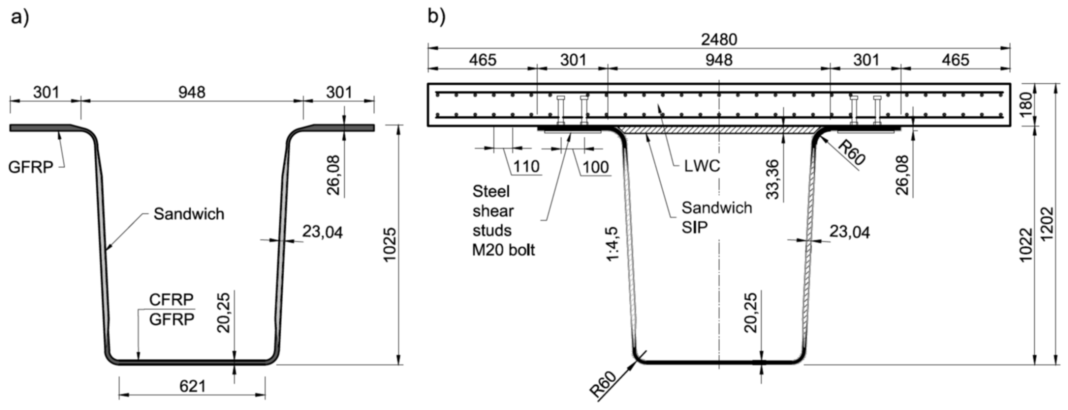
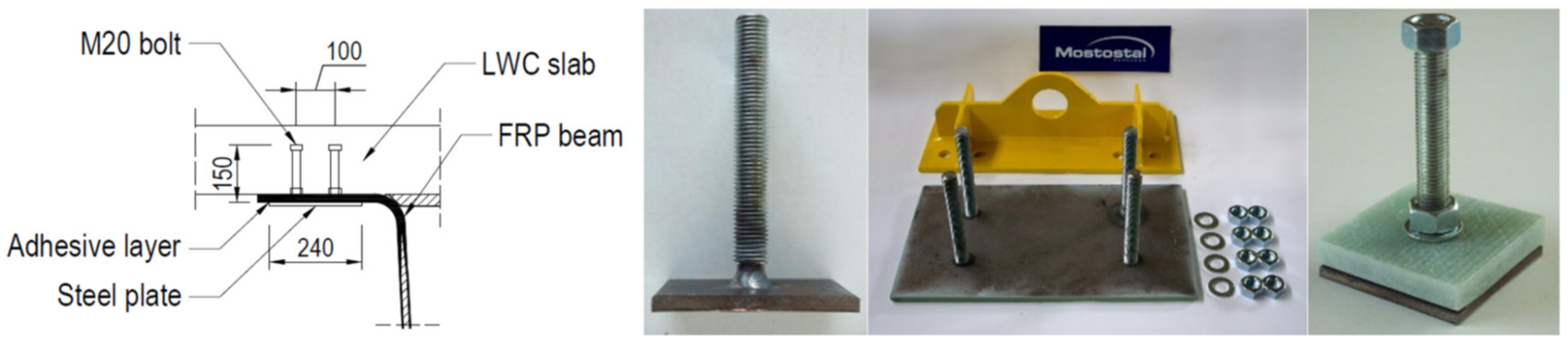
2. FRP-Concrete Hybrid Bridge Girder and Shear Connection System
3. Shear Connection Design
4. Static Tests
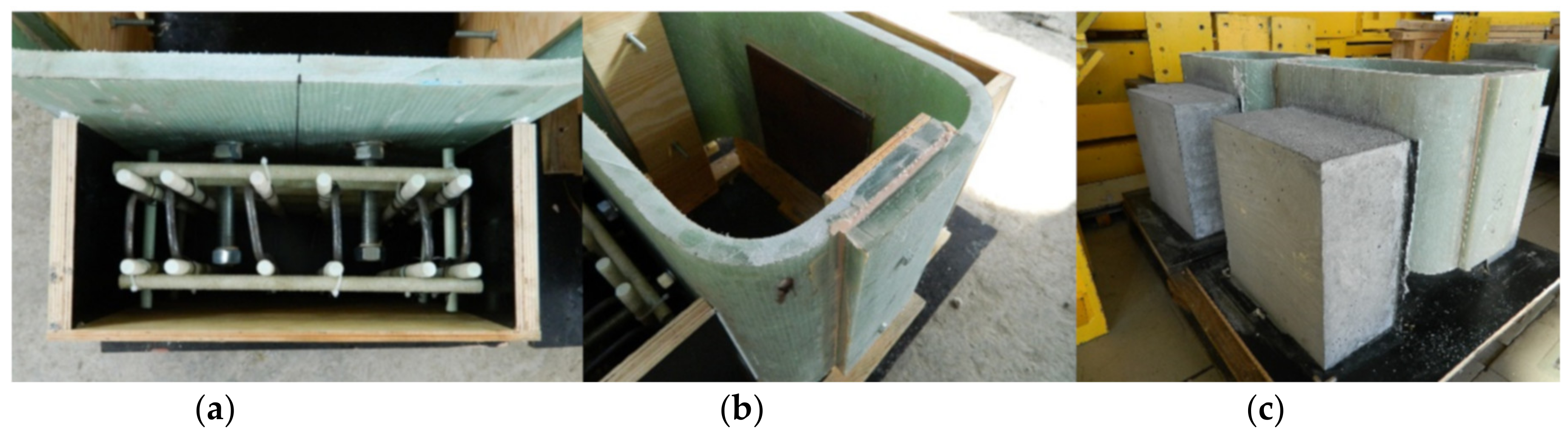
4.1. Specimens’ Fabrication
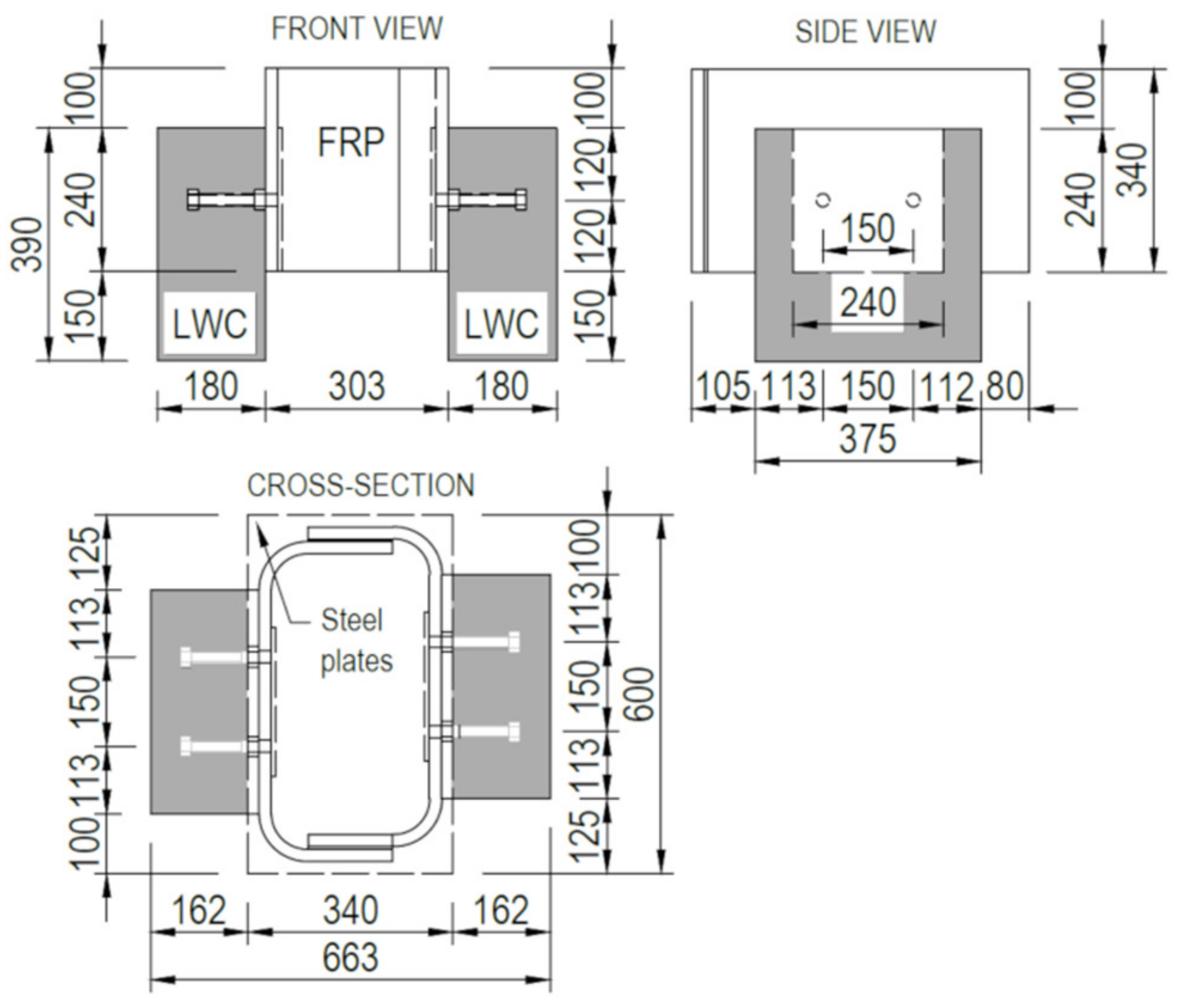
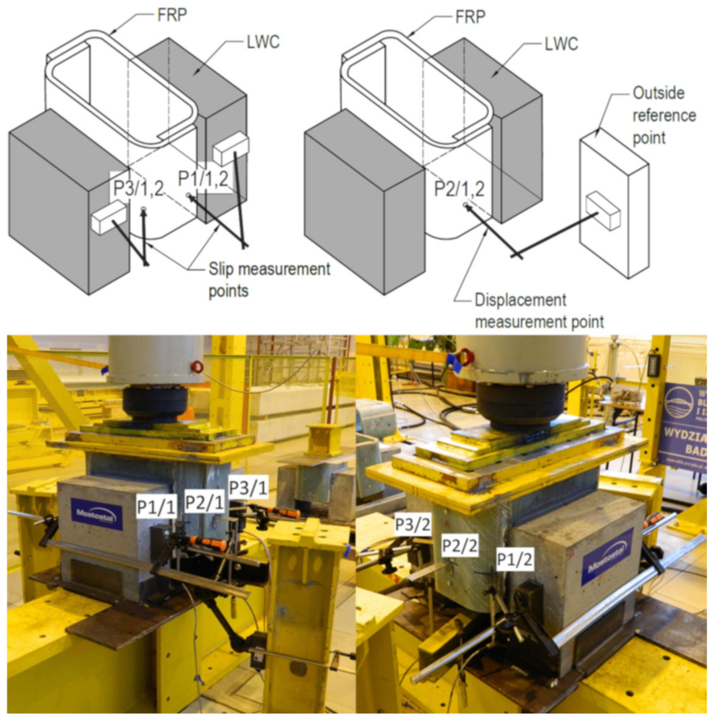
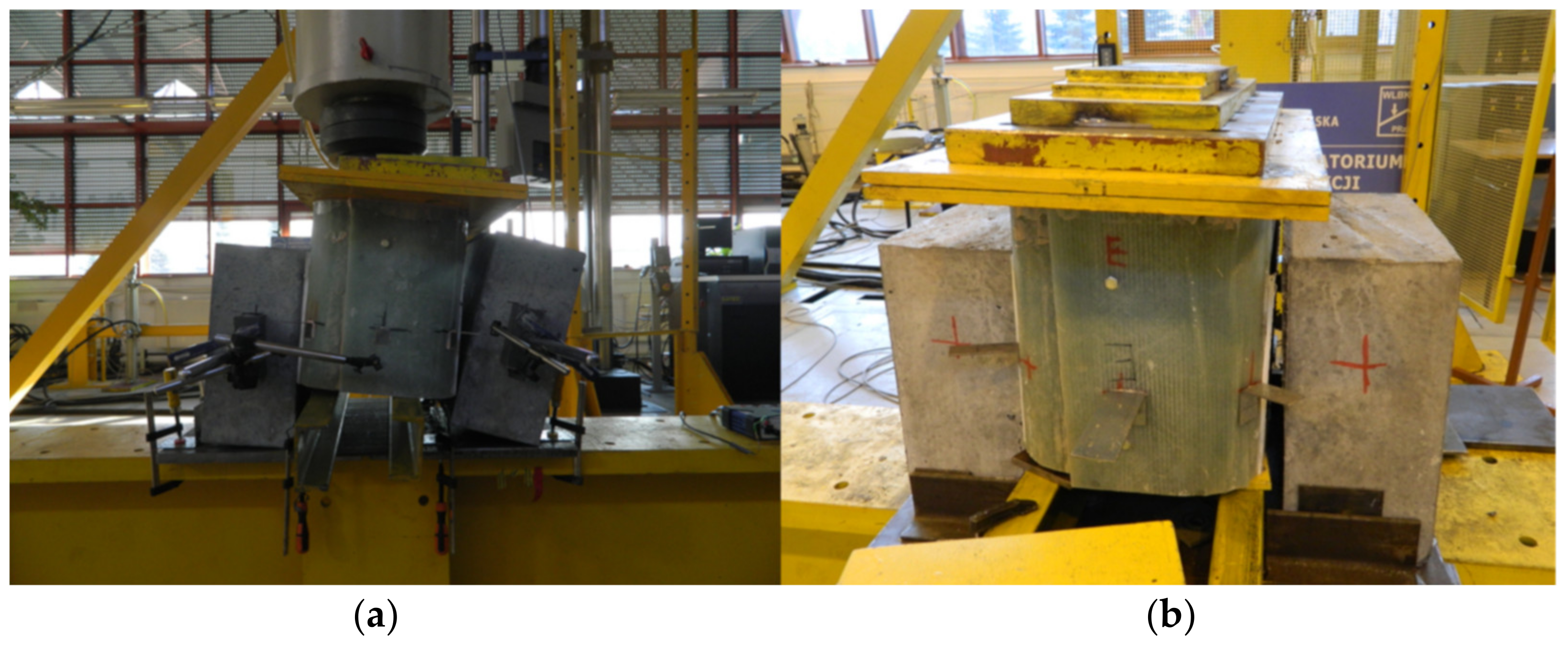
4.2. Test Setup
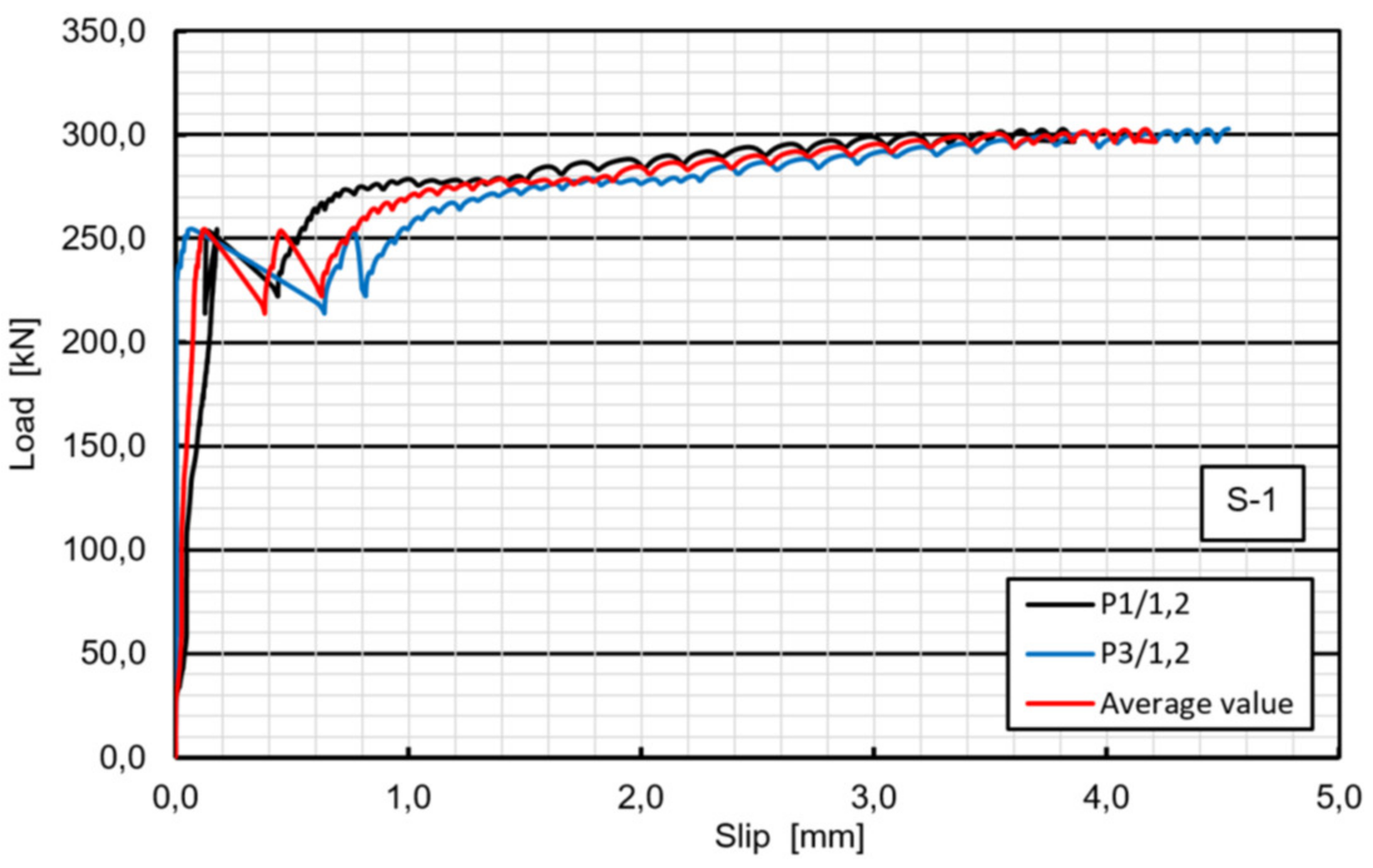
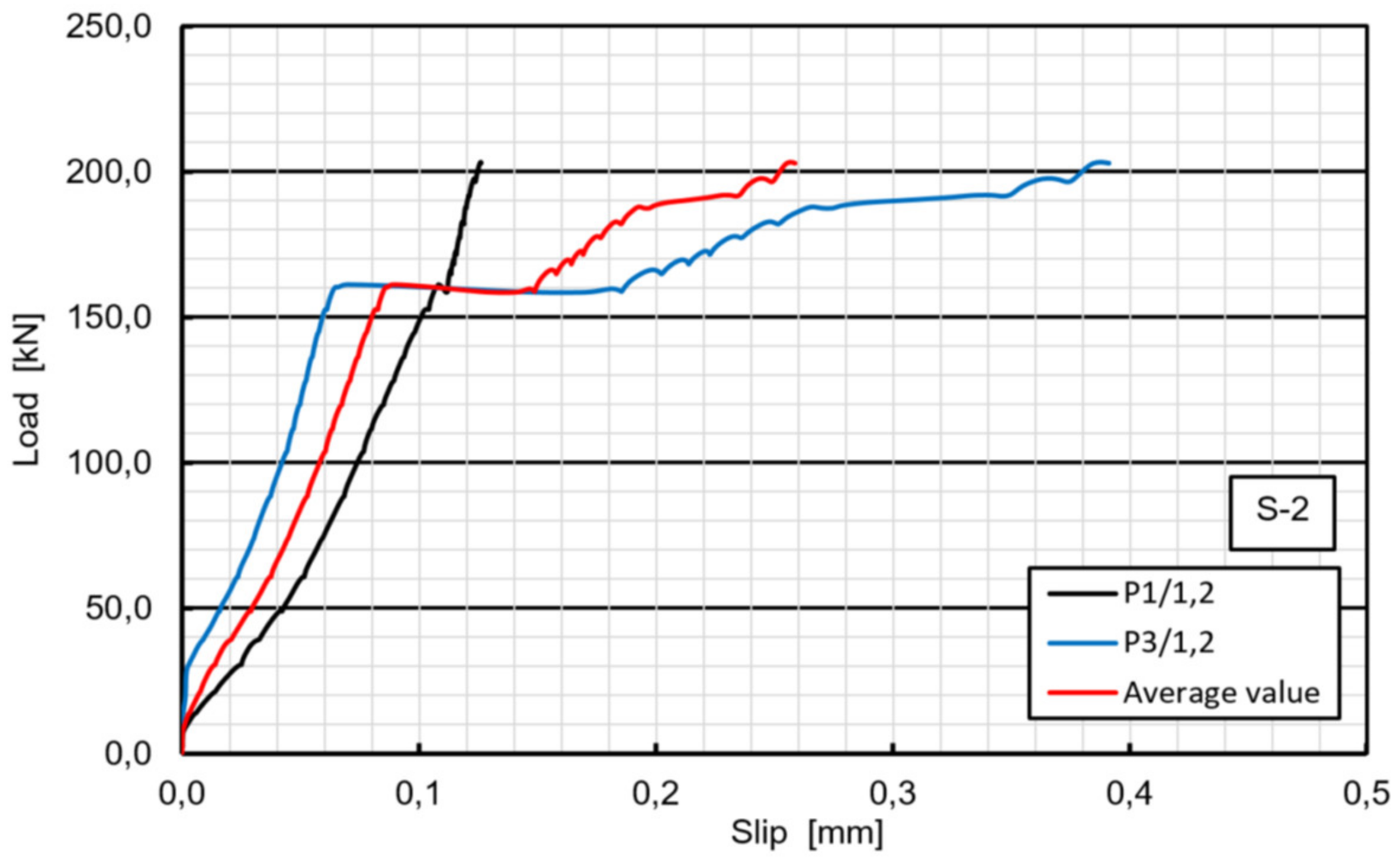
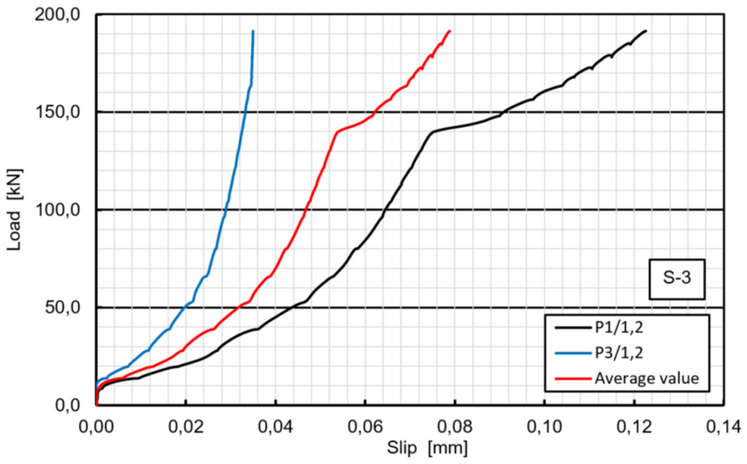
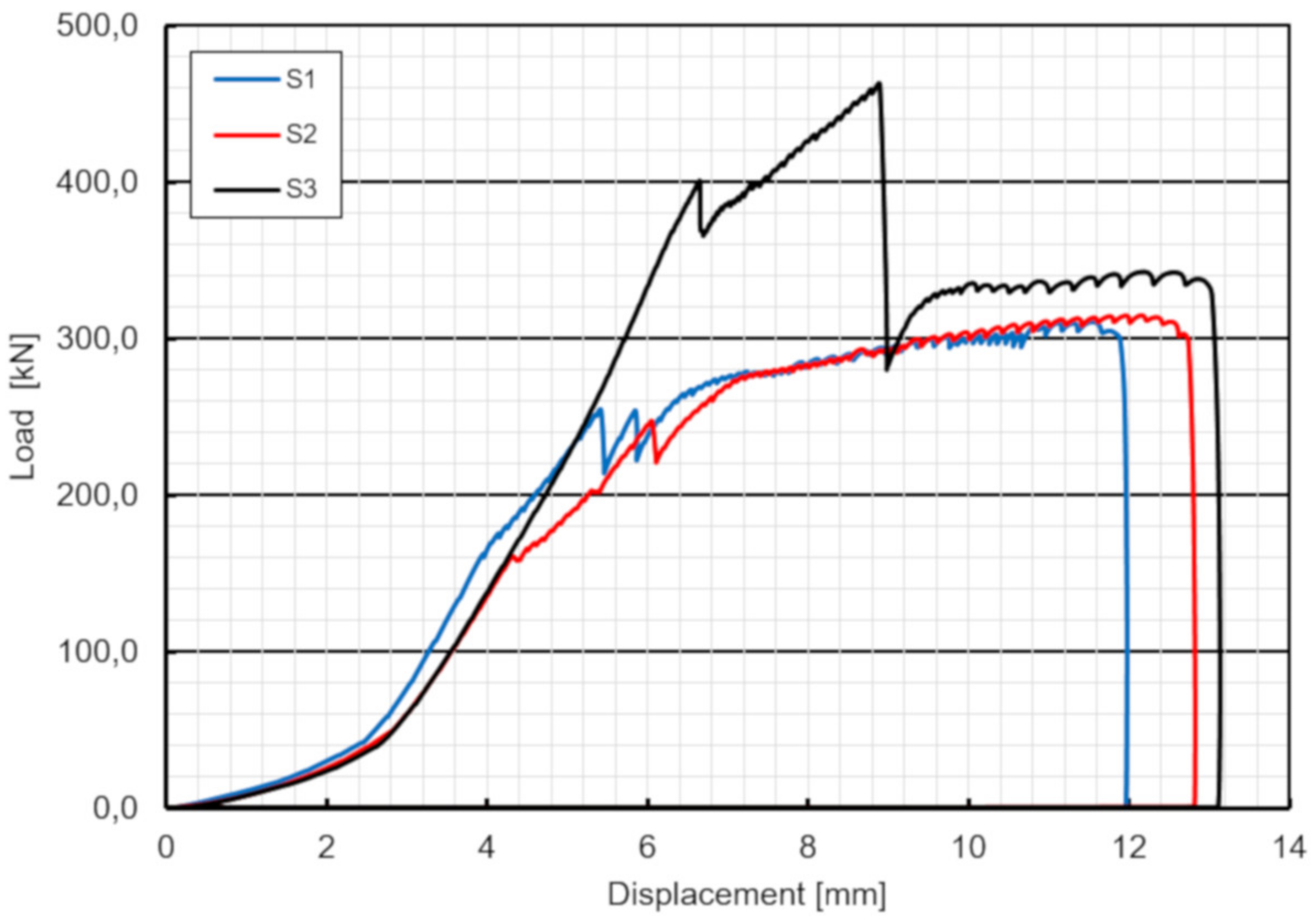
4.3. Test Results
5. Fatigue Test
5.1. Test Setup
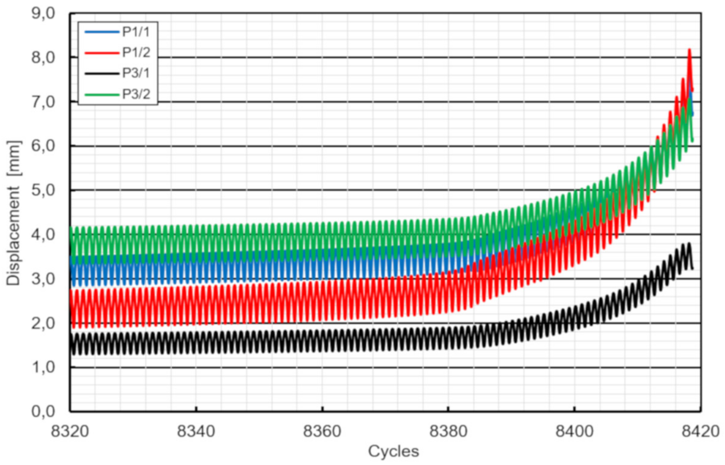
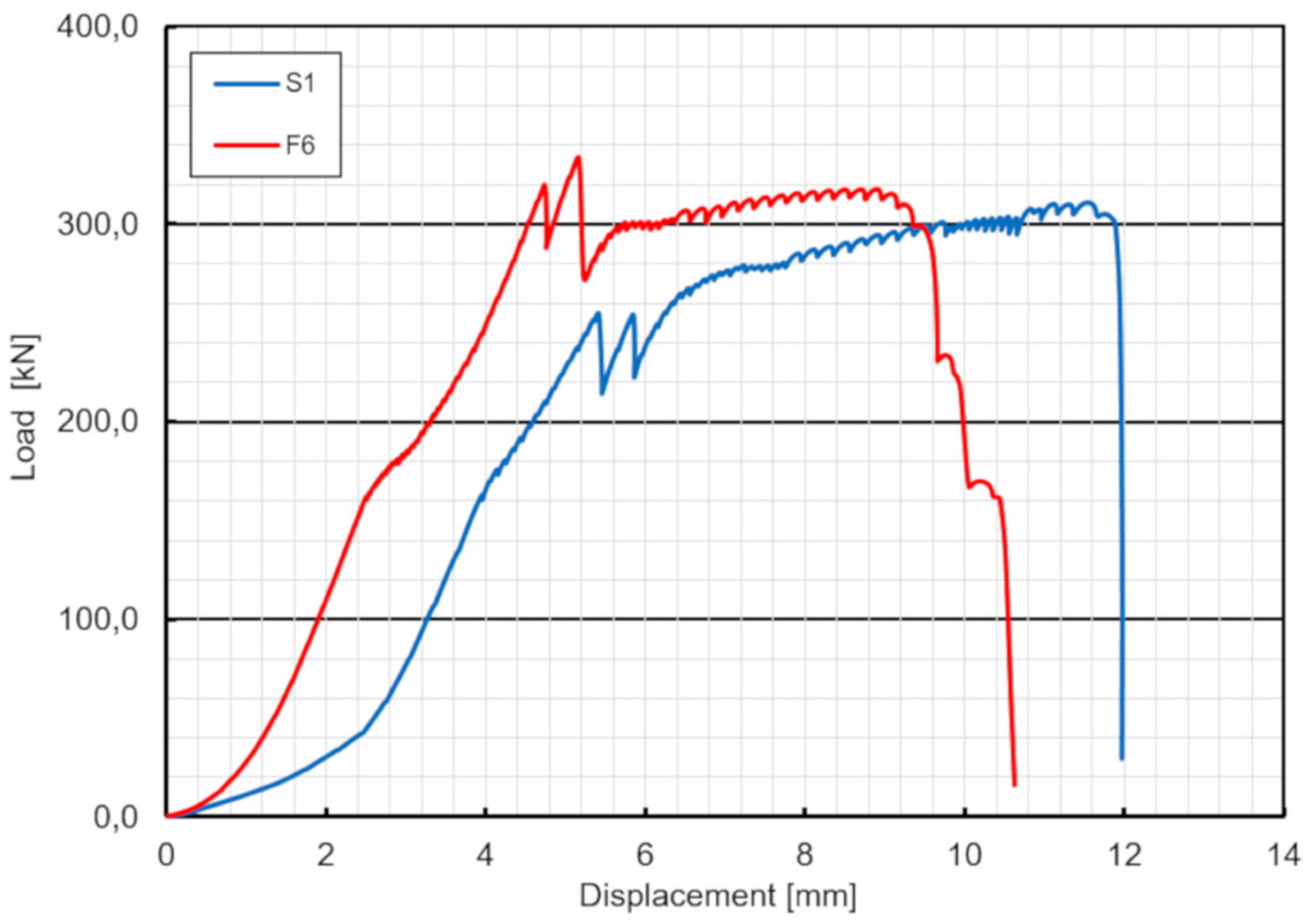
5.2. Test Results
6. Discussion
6.1. Load-Slip Behavior
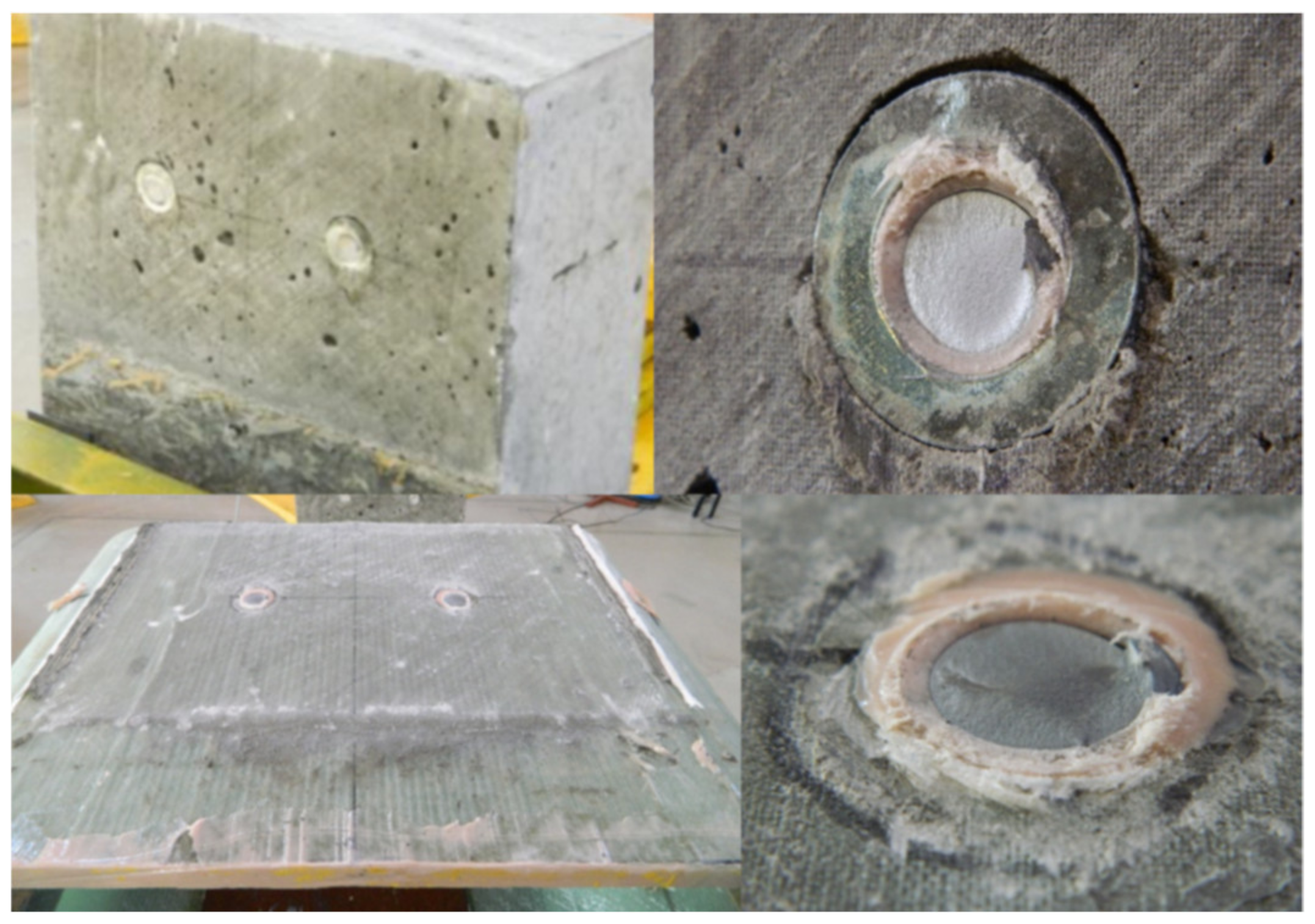
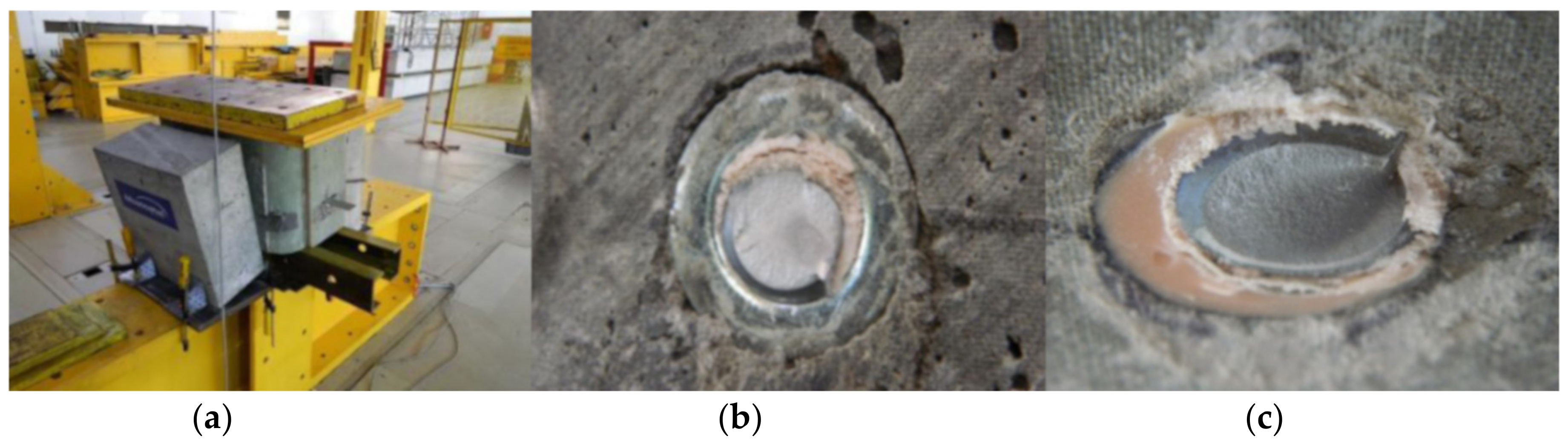
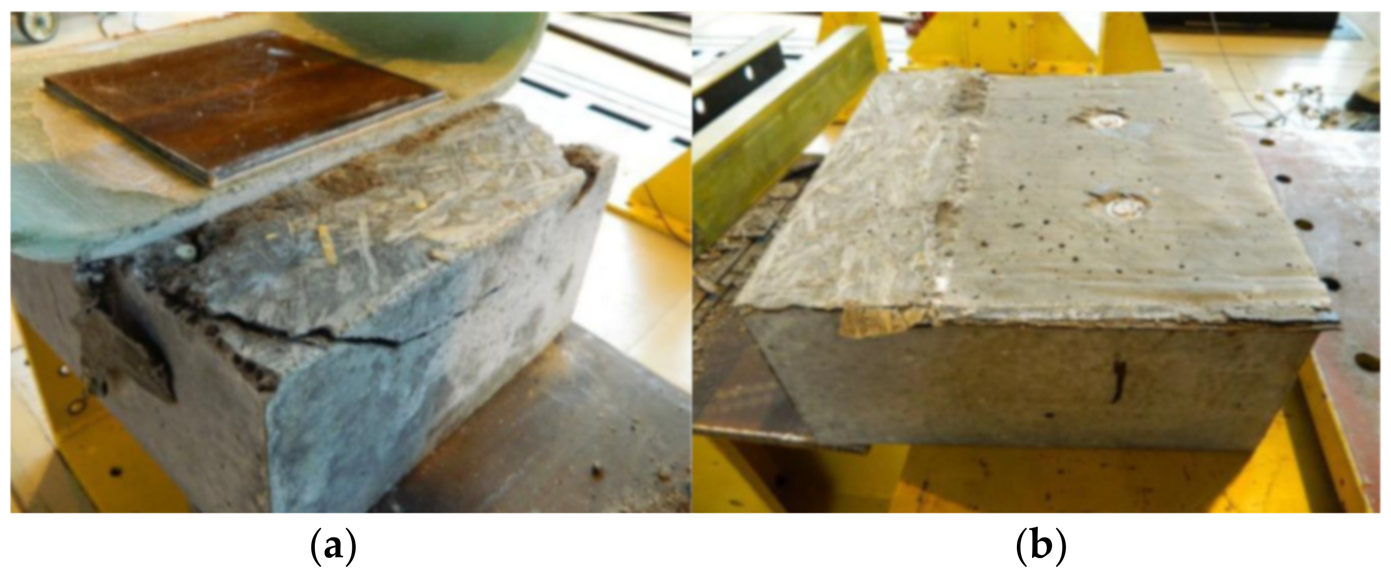
6.2. Failure Mechanism
6.3. Shear Capacity
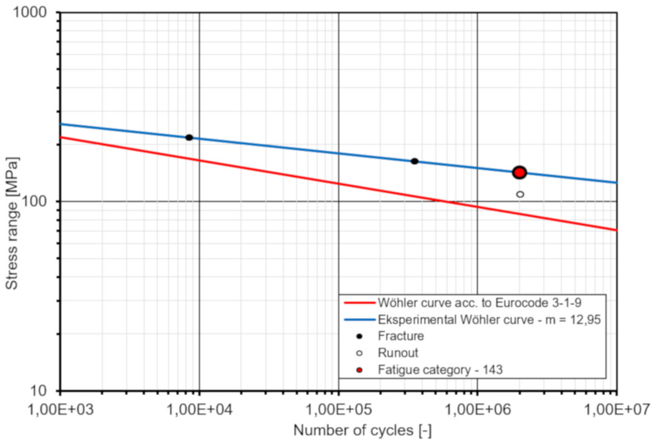
6.4. Fatigue Strength
7. Conclusions
- •
- the load—slip behavior of the GFRP–concrete specimens is more ductile than that of typical steel-concrete specimens;
- •
- the average slip modulus kslip value is approximately 523 kN/mm, indicating that the connectors can promote the composite action very efficiently;
- •
- bolt shank fracture is the only failure mode, found in the static tests, while the weld toe fracture in welds joining shear bolts to steel plate was the failure mode in fatigue; these may be a preferable failure modes for designing of FRP–concrete hybrid girders with the use of the novel shear connectors;
- •
- the average ultimate resistance obtained from the test is about 12% higher than the characteristic resistance of shear studs according to Eurocode 4 [32];
- •
- the fatigue strength curve slope m = 12.95 and the reference value Δτc = 42.6 MPa at two million cycles are determined; thus, the fatigue strength obtained from the test is 1.66 higher when compared to the fatigue strength of shear studs according to Eurocode 4 [32];
- •
- the global safety factor of the shear connection is estimated as 3.67 showing the high safety, reliability and robustness of the novel connection system,
- •
- Eurocode 4 [32] slightly underestimates the shear capacity and the fatigue strength of the novel connection; however, despite this conservatism this code can be used to predict the strength of the connection and to check its ULS/SLS design provisions.
8. Patents
Author Contributions
Funding
Acknowledgments
Conflicts of Interest
Appendix A
- •
- fu = 400 MPa—for 4.8 class bolt acc. to Eurocode 3–1-8 [34],
- •
- fck = 35.0 MPa—approved by testing for 35/38 class LWC acc. to Eurocode 2–1-1 [36],
- •
- Ecm = 26.968 GPa—determined by testing for 35/38 class LWC acc. to Eurocode 2–1-1 [36] and for concrete density ρ = 1968 kg/m3,
- •
- d = 16.94 mm—nominal dimeter for M20 bolt acc. to [37],
- •
- hsc = 150 mm,
- •
- γV = 1.25—the partial factor for ultimate limit states (ULS),
- •
- ks = 0.75—the reduction factor for serviceability limit states (SLS),
- •
- PRk1 = 72.15 kN—shear resistance of stud’s shank,
- •
- PRk2 = 80.91 kN—concrete crushing resistance,
- •
- PRd,ULS = 57.72 kN—design resistance for ULS verification,
- •
- PRd,SLS = 43.29 kN design resistance for SLS verification.
- •
- VEd,k = 21.98 kN—maximum characteristic shear force for SLS checking,
- •
- VEd,d = 31.34 kN—maximum design shear force for ULS checking.
- •
- EFRP = 71.924 GPa—equivalent modulus of elasticity of FRP beam with respect to bottom edge,
- •
- Ecz (t) = 26.986—short term modulus of elasticity of concrete slab,
- •
- Ecw (t) = 18.549—long term modulus of elasticity of concrete slab,
- •
- nLz = EFRP/Ecz (t) = 71.924/26.986 = 2.665—modular ratio for short term loads,
- •
- nLw = EFRP/Ecw (t) = 71.924/18.549 = 3.878—modular ratio for long term loads including creep,
- •
- Ac = 0.18 × 2.62 = 0.472 m2—cross-section area of concrete slab,
- •
- zz = 97.18 mm—distance between gravity center of concrete slab and neutral axis of hybrid (composite) girder for short term loads,
- •
- zw = 133.20 mm—distance between gravity center of concrete slab and neutral axis of hybrid (composite) girder for long term loads including creep,
- •
- Scz = 0.0172 m3—static moment of area for short term loads,
- •
- Scw = 0.0162 m3—static moment of area for long term loads,
- •
- Icz = 0.0188 m4—second moment of area for short term loads,
- •
- Icw = 0.0180 m4—second moment of area for short term loads.
- •
- max (vL,Ed,k) = 488.40 kN/m,
- •
- max (vL,Ed,d) = 696.43 kN/m.
- •
- li—length of segment (the girder total length is divided into n segments),
- •
- Ni—number of studs per row in segment (constant density per segment).
References
- Burgoyne, C. Advanced composites in civil engineering in Europe. Struct. Eng. Int. 1999, 9, 267–273. [Google Scholar] [CrossRef]
- Holloway, L.C.; Head, P.R. Advanced Polymer Composites and Polymers in the Civil Infrastructure; Elsevier Science Ltd.: London, UK, 2001. [Google Scholar]
- Keller, T. Overview of fibre-reinforced polymers in bridge construction. Struct. Eng. Int. 2002, 12, 66–70. [Google Scholar] [CrossRef]
- O’Connor, J.S. GRP bridge decks and superstructures in the USA. Reinf. Plast. 2008, 52, 26–31. [Google Scholar] [CrossRef]
- Kendall, D. Developments in FRP bridge design. Reinf. Plast. 2010, 54, 38–42. [Google Scholar] [CrossRef]
- Zoghi, M. (Ed.) The International Handbook of FRP Composites in Civil Engineering; CRC Press, Taylor & Francis Group: Abington, UK, 2013. [Google Scholar]
- Chróścielewski, J.; Miśkiewicz, M.; Pyrzowski, Ł.; Sobczyk, B.; Wilde, K. A novel sandwich footbridge—Practical application of laminated composites in bridge design and in situ measurements of static response. Compos. B Eng. 2017, 126, 153–161. [Google Scholar] [CrossRef]
- Siwowski, T.; Kaleta, D.; Rajchel, M. Structural behaviour of an all-composite road bridge. Compos. Struct. 2018, 192, 555–567. [Google Scholar] [CrossRef]
- Hollaway, L.C. A review of the present and future utilisation of FRP composites in the civil infrastructure with reference to their important in-service properties. Constr. Build. Mater. 2010, 24, 2419–2445. [Google Scholar] [CrossRef]
- Cheng, L.; Karbhari, V.M. New bridge systems using FRP composites and concrete: A state-of-the-art review. Prog. Struct. Eng. Mater. 2006, 8, 143–154. [Google Scholar] [CrossRef]
- Gutiérrez, E.; Primi, S.; Mieres, J.M.; Calvo, I. Structural testing of a vehicular carbon fiber bridge: Quasi-static and short-term behavior. J. Bridge Eng. 2008, 13, 271–281. [Google Scholar] [CrossRef]
- Ziehl, P.H.; Engelhardt, M.D.; Fowler, T.J.; Ulloa, F.V.; Medlock, R.D.; Schell, E. Design and field evaluation of hybrid FRP/reinforced concrete superstructure system. J. Bridge Eng. 2009, 14, 309–318. [Google Scholar] [CrossRef]
- Yang, L. Research status of FRP-concrete composite beam/bridge deck systems. Appl. Mech. Mater. 2014, 587–589, 1424–1429. [Google Scholar] [CrossRef]
- Siwowski, T.; Kaleta, D.; Rajchel, M.; Własak, L. The first Polish road bridge made of FRP composites. Struct. Eng. Int. 2017, 27, 308–314. [Google Scholar] [CrossRef]
- Deskovic, N.; Triantafillou, T.C.; Meier, U. Innovative design of FRP combined with concrete: Short term behavior. J. Struct. Eng. 1995, 121, 1069–1078. [Google Scholar] [CrossRef]
- Kitane, Y.; Aref, A. Static and fatigue testing of hybrid fiber-reinforced polymer—Concrete bridge superstructure. J. Compos. Constr. 2004, 8, 182–190. [Google Scholar] [CrossRef]
- Correia, J.R.; Branco, F.A.; Ferreira, J.G. Flexural behaviour of GFRP-concrete hybrid beams with interconnection slip. Compos. Struct. 2007, 77, 66–78. [Google Scholar] [CrossRef]
- Chakrabortty, A.; Khennane, A.; Kayali, O.; Morozov, E. Performance of outside filament-wound hybrid FRP-concrete beams. Compos. B Eng. 2011, 42, 907–915. [Google Scholar] [CrossRef]
- Manalo, A.C.; Aravinthan, T.; Mutsuyoshi, H.; Matsui, T. Composite behaviour of a hybrid FRP bridge girder and concrete deck. Adv. Struct. Eng. 2012, 15, 589–600. [Google Scholar] [CrossRef]
- Siwowski, T.; Rajchel, M. Structural performance of a hybrid FRP composite—Lightweight concrete bridge girder. Compos. B Eng. 2019, 174, 107055. [Google Scholar] [CrossRef]
- Cho, K.; Park, S.Y.; Kim, S.T. Shear connection system and performance evaluation of FRP-concrete composite deck. KSCE J. Civ. Eng. 2010, 14, 855–865. [Google Scholar] [CrossRef]
- Nordin, H.; Täljsten, B. Testing of hybrid FRP composite beams in bending. Compos. B Eng. 2004, 35, 27–33. [Google Scholar] [CrossRef]
- Nelson, M.; Fam, A. Structural GFRP permanent forms with T-shape ribs for bridge decks supported by precast concrete girders. J. Bridge Eng. 2012, 18, 813–826. [Google Scholar] [CrossRef]
- Canning, L.; Hollaway, L.; Thorne, A.M. An investigation of the composite action of an FRP/concrete prismatic beam. Constr. Build. Mater. 1999, 13, 417–426. [Google Scholar] [CrossRef]
- Nguyen, H.; Mutsuyoshi, H.; Zatar, W. Push-out tests for shear connections between UHPFRC slabs and FRP girder. Compos. Struct. 2014, 118, 528–547. [Google Scholar] [CrossRef]
- Zou, X.; Feng, P.; Wang, J. Bolted shear connection of FRP-concrete hybrid beams. J. Compos. Constr. 2018, 22, 04018012. [Google Scholar] [CrossRef]
- Fam, A.; Skutezky, T. Composite T-beams using reduced-scale rectangular FRP tubes and concrete slabs. J. Compos. Constr. 2006, 10, 172–181. [Google Scholar] [CrossRef]
- Honickman, H.N. Pultruded GFRP Sections as Stay-in-Place Structural Open Formwork for Concrete Slabs and Girders. Master’s Thesis, Queen’s University, Kingston, ON, Canada, July 2008. [Google Scholar]
- Zou, X.; Feng, P.; Wang, J. Perforated FRP ribs for shear connecting of FRP-concrete hybrid beams/decks. Compos. Struct. 2016, 152, 267–276. [Google Scholar] [CrossRef]
- Wiater, A.; Rajchel, M.; Siwowski, T. Research on deck slabs made of lightweight concrete and reinforced with GFRP bars. J. Civ. Eng. Env. Arch. 2015, XXXII, 469–492. (In Polish) [Google Scholar]
- Siwowski, T.; Rajchel, M.; Kulpa, M. Design and field evaluation of a hybrid FRP composite—Lightweight concrete road bridge. Compos. Struct. 2019, 230, 111504. [Google Scholar] [CrossRef]
- Eurocode 4: Design of Composite Steel and Concrete Structures—Part 2: General Rules and Rules for Bridges; EN 1994-2; European Committee for Standardization: Brussels, Belgium, 2005.
- Eurocode 4: Design of Composite Steel and Concrete Structures—Part 1-1: General Rules and Rules for Buildings; EN 1994-1-1; European Committee for Standardization: Brussels, Belgium, 2004.
- Eurocode 3: Design of Steel Structures—Part 1-8: Design of Joints; EN 1993-1-8; European Committee for Standardization: Brussels, Belgium, 2005.
- Zou, X.; Feng, P.; Wang, J.; Wu, Y.; Feng, Y. FRP stay-in-place form and shear key connection for FRP-concrete hybrid beams/decks. Compos. Struct. 2018, 192, 489–499. [Google Scholar] [CrossRef]
- Eurocode 2: Design of Concrete Structures—Part 1-1: General Rules and Rules for Buildings; EN 1992-1-1; European Committee for Standardization: Brussels, Belgium, 2004.
- ISO General Purpose Metric Screw Threads—General Plan; PN ISO 261:2001; Polish Committee for Standardization: Warsaw, Poland, 2001.
- Rajchel, M.; Siwowski, T. Live load transverse distribution in a road slab-girder bridge made of FRP composite girders. Road Bridge 2017, 16, 131–145. [Google Scholar] [CrossRef]
- Eurocode 1: Actions on Structures—Part 2: Traffic Loads on Bridges; EN 1991-2; European Committee for Standardization: Brussels, Belgium, 2003.


| Load | Total Shear Force Per Unit Length vL,Ed | Maximum Shear Force VEd | Maximum Shear Force Per Study PEd |
|---|---|---|---|
| [kN/m] | [kN] | [kN] | |
| Characteristic | 488.40 | 349.44 | 21.98 |
| Design SLS | 488.40 | 349.44 | 21.98 |
| Design ULS | 696.43 | 523.02 | 31.34 |
| Constant, Parameter | Unit | Symbol, Direction | Lamina | ||
|---|---|---|---|---|---|
| X-E ±45° | B-E 0/90° | U-E 0° (90°) | |||
| 1210 g/m2 | 800 g/m2 | 1210 g/m2 | |||
| Longitudinal modulus of elasticity | GPa | Ex | 20.50 | 20.00 | 42.13 |
| Ey | 20.50 | 20.00 | 10.87 | ||
| Transverse modulus of elasticity | GPa | Gxy | 3.90 | 3.90 | 4.40 |
| Gyz | 3.04 | 2.83 | 2.71 | ||
| Gxz | 3.04 | 2.83 | 2.71 | ||
| Poisson’s ratio | - | νxy | 0.019 | 0.029 | 0.29 |
| νyz | 0.019 | 0.029 | 0.075 | ||
| νxz | 0.019 | 0.029 | 0.075 | ||
| Tensile strength | MPa | Xt | 520.0 | 522.0 | 855.0 |
| Yt | 520.0 | 522.0 | 44.0 | ||
| Compressive strength | MPa | Xc | 320.0 | 321.0 | 537.0 |
| Yc | 320.0 | 321.0 | 84.0 | ||
| Shear strength | MPa | Sxy | 60.0 | 60.0 | 51.0 |
| Syz | 30.0 | 30.0 | 25.0 | ||
| Sxz | 30.0 | 30.0 | 25.0 |
| Constant, Parameter | Unit | Symbol, Direction | Value |
|---|---|---|---|
| Modulus of elasticity | GPa | Ec | 26.986 |
| Tensile strength | MPa | ft | 2.46 |
| Compressive strength | MPa | fc | 25.76 |
| Ultimate compressive strain | [‰] | εlcu1 | 1.749 |
| Density | kg/m3 | ρ | 1968 |
| Specimen | First Slip | Failure | |||||
|---|---|---|---|---|---|---|---|
| Slip Load Ps | First Slip δ1 | Modulus kslip | Ultimate Load Pu | Ultimate Slip δu | Ultimate Resistance Pr | Mode | |
| [kN] | [mm] | [kN/mm] | [kN] | [mm] | [kN] | ||
| S1 | 255 | 0.12 | 531.3 | 311 | 4.2 | 77.75 | bolt shank fracture |
| S2 | 245 | 0.30 (0.235) | 204.2 (260.6) | 315 | 4.3 | 78.75 | bolt shank fracture |
| S3 | 405 | 0.16 | 632.8 | 342 | 4.5 | 85.50 | bolt shank fracture |
| F6 | 320 | 0.12 | 666.7 | 315 | 4.9 | 78.75 | bolt shank fracture |
| Average 1 | 522.8 | 322.67 | 80.67 | ||||
| Specimen | Fmin | Fmax | R = Fmin/Fmax | ΔF | ΔF/Pu,av |
|---|---|---|---|---|---|
| [kN] | [kN] | [kN] | [%] | ||
| F4 | 22.2 | 222.2 | 0.1 | 200 | 61.9 |
| F5 | 16.6 | 166.6 | 0.1 | 150 | 46.5 |
| F6 | 11.0 | 111.0 | 0.1 | 100 | 31.0 |
| Specimen | Stress Range ΔτR | Crack Initiation | Number of Cycles at Failure NR | Log (NR)/Log (Nc) acc. to [32] |
|---|---|---|---|---|
| [MPa] | [cycles] | [cycles] | ||
| F4 | 217.7 | 8.384 × 10³ | 8.412 × 10³ | |
| F5 | 163.3 | 2.945 × 10⁵ | 3.488 × 10⁵ | 1.66 |
| F6 | 108.9 | – | run-out |
© 2020 by the authors. Licensee MDPI, Basel, Switzerland. This article is an open access article distributed under the terms and conditions of the Creative Commons Attribution (CC BY) license (http://creativecommons.org/licenses/by/4.0/).
Share and Cite
Rajchel, M.; Kulpa, M.; Siwowski, T. Experimental Study on a Novel Shear Connection System for FRP-Concrete Hybrid Bridge Girder. Materials 2020, 13, 2045. https://doi.org/10.3390/ma13092045
Rajchel M, Kulpa M, Siwowski T. Experimental Study on a Novel Shear Connection System for FRP-Concrete Hybrid Bridge Girder. Materials. 2020; 13(9):2045. https://doi.org/10.3390/ma13092045
Chicago/Turabian StyleRajchel, Mateusz, Maciej Kulpa, and Tomasz Siwowski. 2020. "Experimental Study on a Novel Shear Connection System for FRP-Concrete Hybrid Bridge Girder" Materials 13, no. 9: 2045. https://doi.org/10.3390/ma13092045
APA StyleRajchel, M., Kulpa, M., & Siwowski, T. (2020). Experimental Study on a Novel Shear Connection System for FRP-Concrete Hybrid Bridge Girder. Materials, 13(9), 2045. https://doi.org/10.3390/ma13092045