Modeling of Boring Mandrel Working Process with Vibration Damper

 ,
,  , ,
, ,  and
and 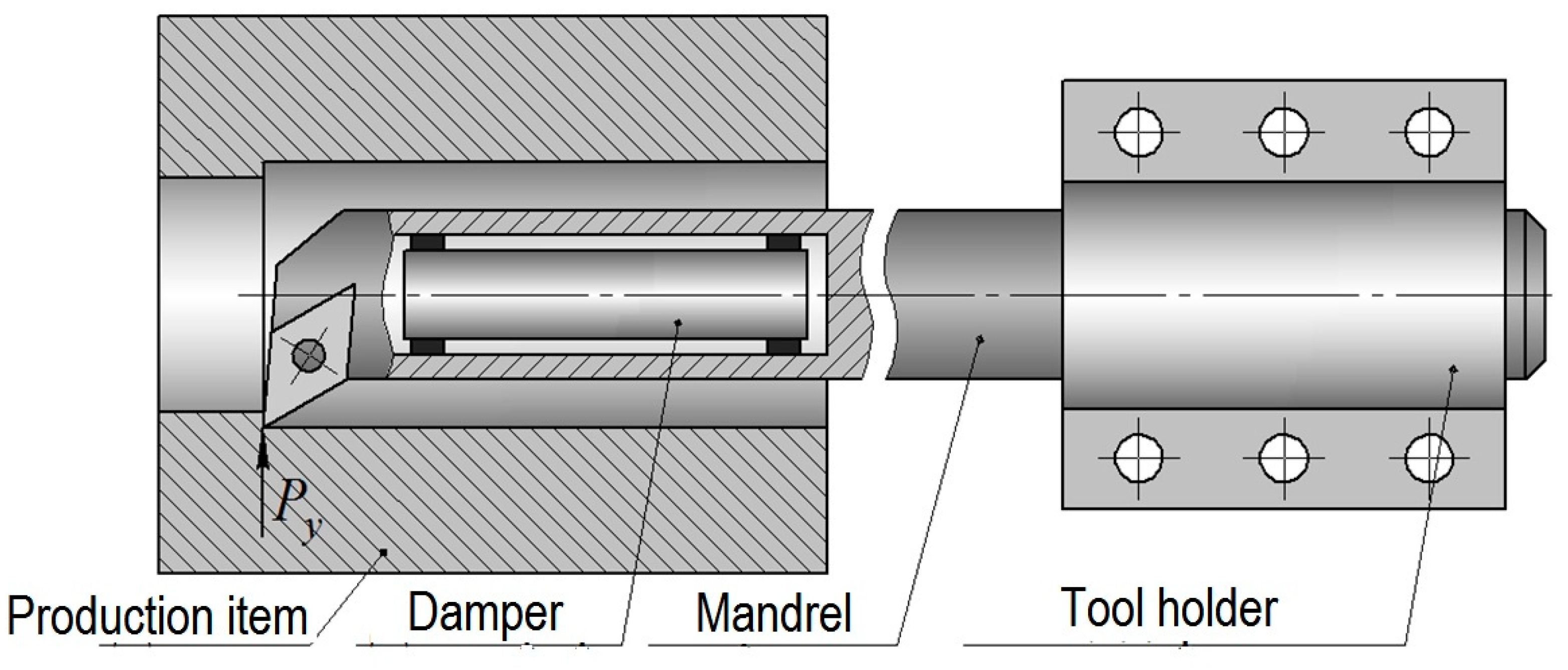
Abstract
1. Introduction
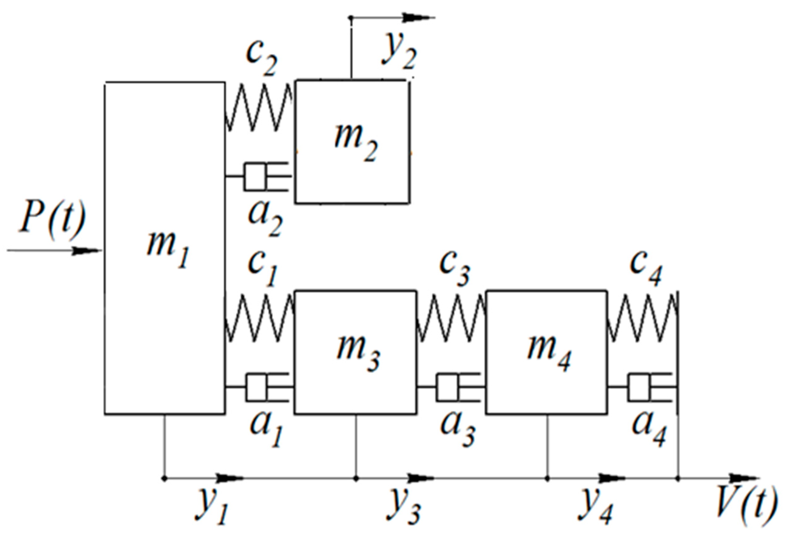
2. Design of Mathematical Model
- machine support with a tool holder;
- boring mandrel;
- inertial body (damper).
- the natural vibrations frequency (approximately 150–250 Hz) that arise due to the occurrence of self-oscillations characteristic of the sharpening process;
- the forced vibrations frequency (approximately 400–600 Hz) that arises as a result of the chip formation process.
- the elastic resistance force, proportional to the movement,
- the viscous resistance force, proportional to the speed of movement.
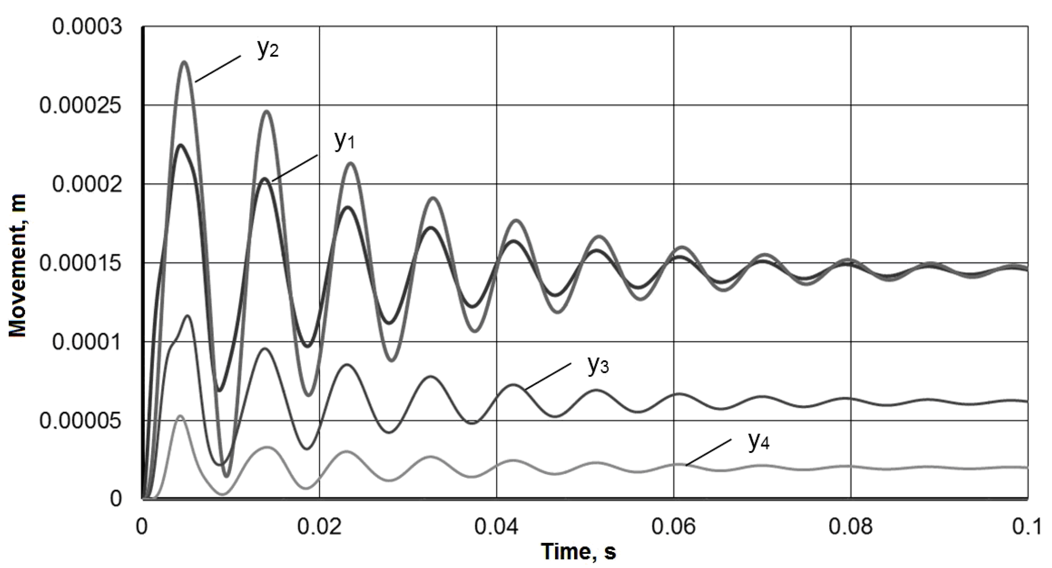
3. Results
4. Discussion
5. Conclusions
- This dynamic model was made including the mandrel separation into segments with different parameters of:
- -
- mass,
- -
- stiffness and damping.
- The segmentation allowed to describe the operation of the hole boring process with such a mandrel with a damper more accurately.
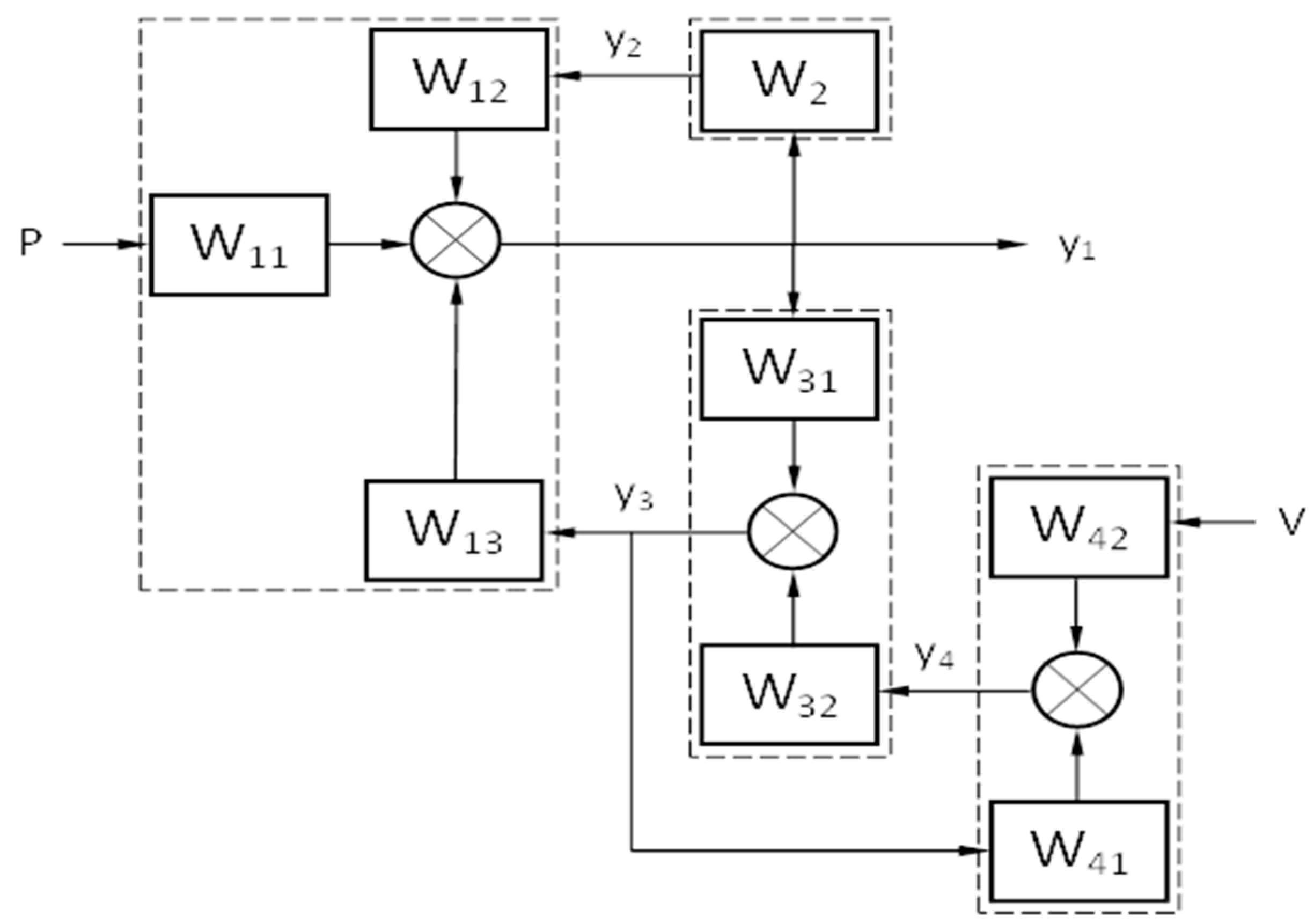
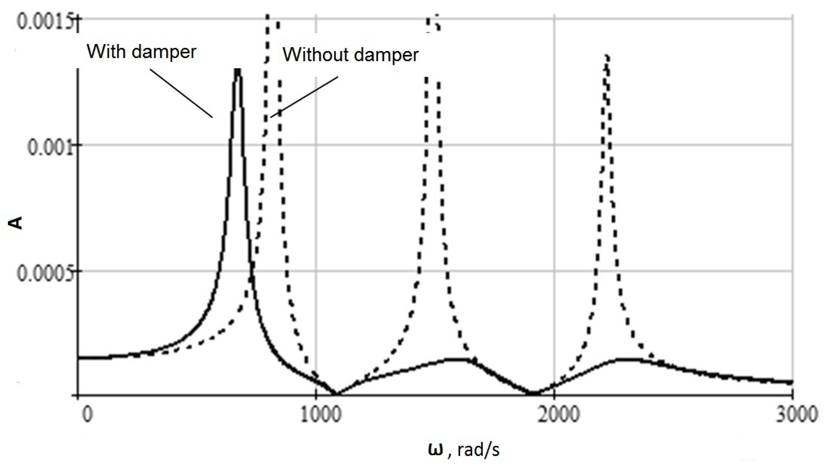
- The proposed representation of a mathematical model of differential equations system in the form of a structural diagram of interacting dynamic elements with transfer functions allowed:
- -
- to obtain a common frequency complex transfer function of the entire system,
- -
- for its subsequent transformation into an amplitude-frequency characteristic.
- This solution allows to find a safe frequency range with a minimum amplitude of the instrumental system vibration.
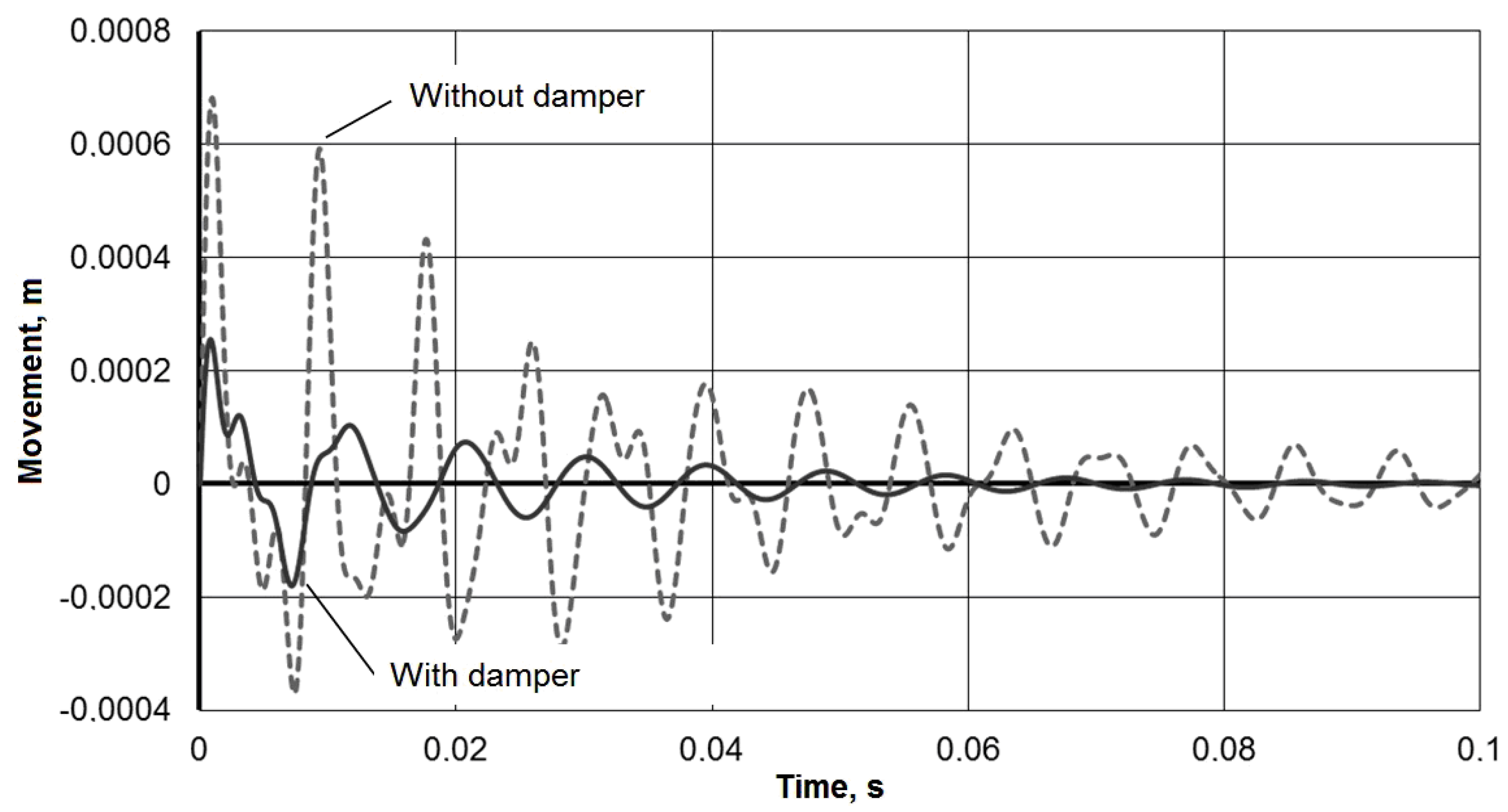
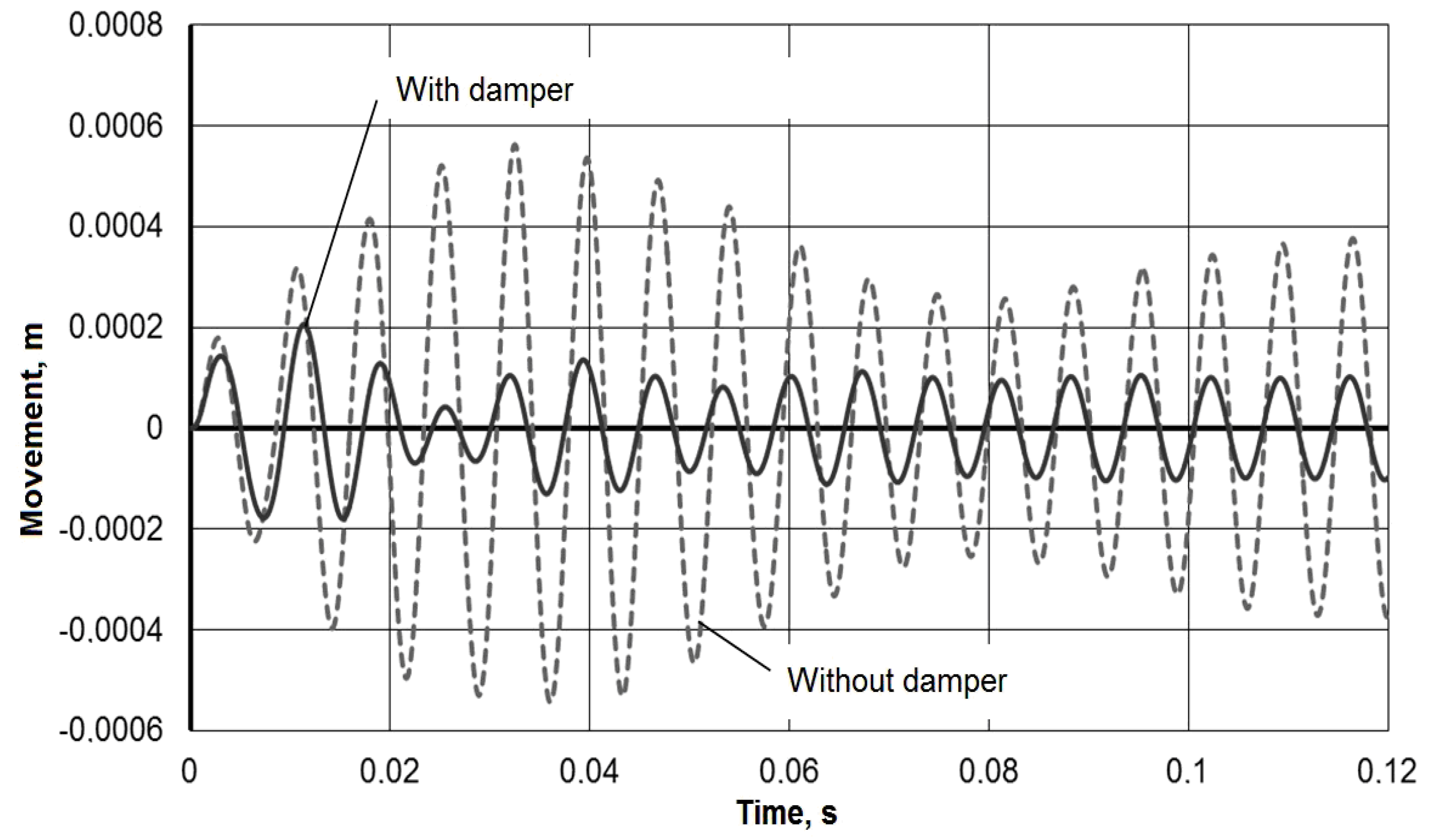
- Important for the technological process for this dynamic mathematical model of the technological system is the finding that the vibration amplitude:
- -
- can be reduced 2–3 times during impulse action on the tool,
- -
- at steady state during a frequency exposure also decreases significantly up to 4 times.
Author Contributions
Funding
Conflicts of Interest
References
- Skoric, S.; Udiljak, T.; Ciglar, D. Study of the suitability of the machining of rotating surfaces. J. Trans. Famena 2008, 32, 69–83. [Google Scholar]
- Ajaja, J.; Jomaa, W.; Bocher, P.; Chromik, R.R.; Brochu, M. High cycle fatigue behavior of hard turned 300 M ultra-high strength steel. Int. J. Fatigue 2020, 131, 105380. [Google Scholar] [CrossRef]
- Pokorný, P.; Peterka, J.; Vaclav, S. The task of 5-axis milling. Teh. Vjesn.-Tech. Gaz. 2012, 19, 147–150. [Google Scholar]
- Vopat, T.; Peterka, J.; Šimna, V. The influence of different types of copy milling on the surface roughness and tool life of end mills. Procedia Eng. 2015, 100, 868–876. [Google Scholar] [CrossRef]
- Zou, F.; Dang, J.; Cai, X.; An, Q.; Ming, W.; Chen, M. Hole quality and tool wear when dry drilling of a new developed metal/composite co-cured material. Proc. Inst. Mech. Eng. Part B J. Eng. Manuf. 2020, 234, 980–992. [Google Scholar] [CrossRef]
- Klaic, M.; Staroveski, T.; Udiljak, T. Tool Wear Classification using Decision Treesin Stone Drilling Applications: A Preliminary Study. Procedia Eng. 2014, 69, 1326–1335. [Google Scholar] [CrossRef]
- Beno, M.; Zvoncan, M.; Kovac, M. Circular interpolation and positioning accuracy deviation measurement on five axis machine tools with different structures. Teh. Vjesn.-Tech. Gaz. 2013, 20, 479–484. [Google Scholar]
- Peterka., J. A new approach to calculating the arithmetical mean deviation of a profile during copy milling. Strojniški Vestnik J. Mech. Eng. 2004, 50, 594–597. [Google Scholar]
- Vopat, T.; Peterka, J.; Kovac, M.; Buranský, I. The wear measurement process of ball nose end mill in the copy milling operations. In Proceedings of the 24th DAAAM International Symposium on Intelligent Manufacturing and Automation, Zadar, Croatia, 23–26 October 2013. [Google Scholar]
- Krolczyk, G.; Legutko, S.; Stoic, A. Influence of the cutting parameters and conditions onto surface hardness of duplex stainless steel after turning. Teh. Vjesn. 2013, 20, 1077–1080. [Google Scholar]
- Yuan, Z.; Hu, J.; Wen, Q.; Cheng, K.; Zheng, P. Investigation on an innovative method for High-Speed Low-Damage Micro-Cutting of CFRP composites with diamond dicing Blades. Materials 2018, 11, 1974. [Google Scholar] [CrossRef]
- Eynian, M.; Altintas, Y. Chatter stability of general turning operations with process damping. J. Manuf. Sci. Eng. 2009, 131, 041005. [Google Scholar] [CrossRef]
- Shao, Q.; Zhao, Z.; Tian, X.; Wang, L. Research on Effect of Decreasing Vibration with Liquid Film Damping in Precision Boring. Wirel. Pers. Commun. 2008, 102, 1085–1094. [Google Scholar] [CrossRef]
- Maruda, W.R.; Feldshtein, E.; Legutko, S.; Krolczyk, M.G. Analysis of Contact Phenomena and Heat Exchange in the Cutting Zone Under Minimum Quantity Cooling Lubrication Conditions. Arab. J. Sci. Eng. 2016, 41, 661–668. [Google Scholar] [CrossRef]
- Maruda, R.; Feldshtein, E.; Legutko, S.; Krolczyk, G. Research on Emulsion Mist Generation in the Conditions of Minimum Quantity Cooling Lubrication (MQCL). Teh. Vjesn. 2015, 22, 1213–1218. [Google Scholar]
- Lie, L.; Beibei, S.; Haitao, H. Nonlinear system modeling and damping implementation of a boring bar. Int. J. Adv. Manuf. Technol. 2019, 104, 921–930. [Google Scholar] [CrossRef]
- Ghorbani, S.; Rogov, V.; Carluccio, A.; Belov, P.S. The effect of composite boring bars on vibration in machining process. Int. J. Adv. Manuf. Technol. 2019, 105, 1157–1174. [Google Scholar] [CrossRef]
- Baranov, M.N.; Bozek, P.; Prajova, V.; Ivanova, T.N.; Novokshonov, D.N.; Korshunov, A. Constructing and calculating of multistage sucker rod string according to reduced stress. Acta Montan. Slovaca 2017, 22, 107–115. [Google Scholar]
- Jingmin, M.; Yongsheng, R. Free vibration and chatter stability of a rotating thin-walled composite bar. Adv. Mech. Eng. 2018, 10. [Google Scholar] [CrossRef]
- Gurraj, S.; Guravtar, M.; Swastik, P. Improving the Surface roughness and Flank wear of the boring process using particle damped boring bars. Mater. Today Proc. 2018, 5, 28186–28194. [Google Scholar]
- Yigit, U.; Cigeroglu, E.; Budak, E. Chatter reduction in boring process by using piezoelectric shunt damping with experimental verification. Mech. Syst. Signal Process. 2017, 94, 312–321. [Google Scholar] [CrossRef]
- Fallah, M.; Moetakef-Imani, B. Analytical Prediction of Stability Lobes for Passively Damped Boring Bars. J. Mech. 2017, 33, 641–654. [Google Scholar] [CrossRef]
- Chockalingam, S.; Natarajan, U.; George, A. Damping investigation in boring bar using hybrid copper-zinc particles. J. Vibr. Control 2017, 23, 2128–2134. [Google Scholar] [CrossRef]
- Kassem, M.; Yang, Z.; Gu, Y.; Wang, W. Active dynamic vibration absorber for flutter suppression. J. Sound Vib. 2020, 469, 1–18. [Google Scholar] [CrossRef]
- Zhang, Q.; Xia, S.; Xu, D.; Peng, Z. A torsion-translation vibration isolator with quasi-zero stiffness. Nonlinear Dyn. 2020, 99, 1467–1488. [Google Scholar] [CrossRef]
- Fu, M.; Zhang, P.; Li, J.H.; Wu, Y.F. Observer and reference governor based control strategy to supperess stick-slip vibrations in oil well drill-string. J. Sound Vib. 2020, 457, 37–50. [Google Scholar] [CrossRef]
- Zhang, C.; Ren, Y.; Ji, S.; Zhang, J. Analysis of the composite boring bar dynamic characteristics considering shear deformation and rotational inertia. Appl. Sci. 2020, 10, 1533. [Google Scholar] [CrossRef]
- Rubio, L.; Loya, J.A.; Miguélez, M.H.; Fernández-Sáez, J. Optimization of passive vibration absorbers to reduce chatter in boring. Mech. Syst. Signal Process. 2013, 41, 691–704. [Google Scholar] [CrossRef]
- Li, L.; Sun, B.; Hua, H. Analysis of the Vibration Characteristics of a Boring Bar with a Variable Stiffness Dynamic Vibration Absorber. Shock Vib. 2019, 2019, 5284194. [Google Scholar] [CrossRef]
- Liu, X.; Liu, Q.; Wu, S.; Liu, L.; Gao, H. Research on the performance of damping boring bar with a variable stiffness dynamic vibration absorber. Int. J. Adv. Manuf. Technol. 2017, 89, 2893–2906. [Google Scholar] [CrossRef]
- Lee, N.; Liu, X.; Wang, J. Structural Design and Vibration Analysis of the Built-in Damping Boring Bar. DEStech Trans. Comput. Sci. Eng. CMSMS 2018, 129–137. [Google Scholar] [CrossRef]
- Lei, X.; Wu, C. Investigating the Optimal Damping Performance of a Composite Dynamic Vibration Absorber with Particle Damping. J. Vib. Eng. Technol. 2018, 6, 503–511. [Google Scholar] [CrossRef]
- Liu, X.; Liu, Q.; Wu, S.; Li, R.; Gao, H. Analysis of the vibration characteristics and adjustment method of boring bar with a variable stiffness vibration absorber. Int. J. Adv. Manuf. Technol. 2018, 98, 95–105. [Google Scholar] [CrossRef]
- Silva, M.M.; Venter, G.S.; Varoto, P.S.; Coelho, R.T. Experimental results on chatter reduction in turning through embendded piezoelectric material and passive shunt circuits. J. Mechatr. 2015, 29, 78–85. [Google Scholar] [CrossRef]
- Chen, F.; Lu, X.; Altintas, Y. A novel magnetic actuator design for active damping of machining tools. Int. J. Mach. Tools Manuf. 2014, 85, 58–69. [Google Scholar] [CrossRef]
- Chen, F.; Hanifzadegan, M.; Altintas, Y.; Lu, X. Active Damping of Boring Bar Vibration with a Magnetic Actuator. IEEE/ASME Trans. Mech. 2015, 20, 2783–2794. [Google Scholar] [CrossRef]
- Lu, X.; Chen, F.; Altintas, Y. Magnetic actuator for active damping of boring bars. CIRP Ann. 2014, 63, 369–372. [Google Scholar] [CrossRef]
- Nagano, S.; Koizumi, T.; Fujii, T.; Tsujiuchi, N.; Ueda, H.; Steel, K. Development of a composite boring bar. Compos. Struct. 1997, 38, 531–539. [Google Scholar] [CrossRef]
- Lee, D.G.; Hwang, H.Y.; Kim, J.K. Design and manufacture of a carbon fiber epoxy rotating boring bar. Compos. Struct. 2003, 60, 115–124. [Google Scholar] [CrossRef]
- Ren, Y.; Fen, W.; Ma, B. Dynamic Modeling of Composite Boring Bars Considering Different Boundary Condition. Mater. Sci. Eng. 2018, 382, 032026. [Google Scholar] [CrossRef]
- Available online: http://booksshare.net/books/physics/timoshenko-sp/1985/files/kolebaniyavinjenernomdele1985.pdf (accessed on 17 April 2020).
- Available online: https://www.twirpx.com/file/22893/ (accessed on 17 April 2020).
- Available online: https://www.twirpx.com/file/30953/ (accessed on 17 April 2020).
- Available online: https://www.twirpx.com/file/608869/ (accessed on 17 April 2020).
- Elbakian, A.; Sentyakov, B.; Sentyakov, K. Modelling of sound impact on primary canvases from Basalt fiber. Acta Simul. Int. Sci. J. Simul. 2018, 4, 1–5. [Google Scholar] [CrossRef]
- Elbakian, A.; Sentyakov, B.; Božek, P.; Kuric, I.; Sentyakov, K. Automated Separation of Basalt Fiber and Other Earth Resources by the Means of Acoustic Vibrations. Acta Montan. Slovaca 2018, 23, 271–281. [Google Scholar]
- Smirnov, V.A.; Repko, A.V. Workpiece Temperature Variations During Flat Peripheral Grinding. Manag. Syst. Prod. Eng. 2018, 26, 93–98. [Google Scholar] [CrossRef]
- Nemeth, M.; Nemethova, A.; Michalconok, G. Determination Issues of Data Mining Process of Failures in the Production Systems. In Artificial Intelligence Methods in Intelligent Algorithms; Springer: Cham, Switzerland, 2019. [Google Scholar]
- Peterka, J.; Vozár, M.; Vopát, T.; Pokorný, P.; Pätoprstý, B. Using multi-criteria analysis to evaluate the impact of drag-finishing technological parameters on the carbide tool radius. Mater. Today Proc. 2020, 22, 205–211. [Google Scholar]
- Jurko, J.; Panda, A.; Behun, M. Prediction of a new form of the cutting tool according to achieve the desired surface quality. Appl. Mech. Mater. 2012, 268–270, 473–476. [Google Scholar] [CrossRef]
- Davidrajuh, R.; Skolud, B.; Krenczyk, D. Performance Evaluation of Discrete Event Systems with GPenSIM. Computers 2018, 7, 8. [Google Scholar] [CrossRef]
- Kalentev, E.; Václav, Š.; Božek, P.; Korshunov, A.; Tarasov, V. Numerical analysis of the stress-strain state of a rope strand with linear contact under tension and torsion loading conditions. Adv. Sci. Technol. Res. J. 2017, 11, 231–239. [Google Scholar] [CrossRef]
- Piska, M. Hard Nano-crystalline coatings for cutting tools. Mater. Sci. Forum 2007, 567–568, 185–188. [Google Scholar] [CrossRef]
- Legutko, S. Development Trends in Machines Operation Maintenance. Eksploatacja i Niezawodnosc Maint. Reliab. 2009, 42, 8–16. [Google Scholar]
- Puchala, W.; Bialy, W.; Bobkowski, G. Possible applications of computer maintenance management systems. Sci. J. Maritime Univ. Szczecin 2005, 5, 403–412. [Google Scholar]


© 2020 by the authors. Licensee MDPI, Basel, Switzerland. This article is an open access article distributed under the terms and conditions of the Creative Commons Attribution (CC BY) license (http://creativecommons.org/licenses/by/4.0/).
Share and Cite
Sentyakov, K.; Peterka, J.; Smirnov, V.; Bozek, P.; Sviatskii, V. Modeling of Boring Mandrel Working Process with Vibration Damper. Materials 2020, 13, 1931. https://doi.org/10.3390/ma13081931
Sentyakov K, Peterka J, Smirnov V, Bozek P, Sviatskii V. Modeling of Boring Mandrel Working Process with Vibration Damper. Materials. 2020; 13(8):1931. https://doi.org/10.3390/ma13081931
Chicago/Turabian StyleSentyakov, Kirill, Jozef Peterka, Vitalii Smirnov, Pavol Bozek, and Vladislav Sviatskii. 2020. "Modeling of Boring Mandrel Working Process with Vibration Damper" Materials 13, no. 8: 1931. https://doi.org/10.3390/ma13081931
APA StyleSentyakov, K., Peterka, J., Smirnov, V., Bozek, P., & Sviatskii, V. (2020). Modeling of Boring Mandrel Working Process with Vibration Damper. Materials, 13(8), 1931. https://doi.org/10.3390/ma13081931