Abstract
Ceramic coatings deposited on orthopedic implants are an alternative to achieve and maintain high wear resistance of the metallic device, and simultaneously allow for a reduction in metal ion release. Silicon nitride based (SiNx) coatings deposited by high power impulse magnetron sputtering (HiPIMS) have shown potential for use in joint replacements, as a result of an improved chemical stability in combination with a good adhesion. This study investigated the effect of N, C, Cr, and Nb content on the tribocorrosive performance of 3.7 to 8.8 µm thick SiNx coatings deposited by HiPIMS onto CoCrMo discs. The coating composition was assessed from X-ray photoelectron spectroscopy and the surface roughness by vertical scanning interferometry. Hardness and Young’s modulus were measured by nanoindentation and coating adhesion was investigated by scratch tests. Multidirectional wear tests against ultrahigh molecular weight polyethylene pins were performed for 2 million cycles in bovine serum solution (25%) at 37 °C, at an estimated contact pressure of 2.1 MPa. Coatings with a relatively low hardness tended to fail earlier in the wear test, due to chemical reactions and eventually dissolution, accelerated by the tribological contact. In fact, while no definite correlation could be observed between coating composition (N: 42.6–55.5 at %, C: 0–25.7 at %, Cr: 0 or 12.8 at %, and Nb: 0–24.5 at %) and wear performance, it was apparent that high-purity and/or -density coatings (i.e., low oxygen content and high nitrogen content) were desirable to prevent coating and/or counter surface wear or failure. Coatings deposited with a higher energy fulfilled the target profile in terms of low surface roughness (Ra < 20 nm), adequate adhesion (Lc2 > 30 N), chemical stability over time in the tribocorrosive environment, as well as low polymer wear, presenting potential for a future application in joint bearings.
1. Introduction
Total joint replacements (TJRs) are surgical procedures carried out most frequently on patients suffering from arthritic pain or bone fractures [1,2,3,4,5]. These procedures are largely considered successful, with success rates up to 90% at 10 years follow-up for total hip replacements (THRs) and total knee replacements (TKRs) [6,7]. However, the aging and more active population places higher demands on these implants.
Typically, for THRs the femoral head is replaced by a metal alloy (CoCrMo) or ceramic (zirconia-toughened alumina (ZTA)), and the acetabulum by a ceramic or polymer (ultrahigh molecular weight polyethylene (UHMWPE) or cross-linked polyethylene (XLPE)) [8,9,10,11,12]. TKRs are composed of a metallic femoral component (CoCrMo) as well as a polyethylene XLPE insert attached in the tray [3,13,14,15,16]. Ceramic coatings on metallic substrates can be used to reduce wear of structural materials, including manufacturing tools as well as joint implants [17,18]. Different types of ceramic coatings are under investigation for hip joint applications (e.g., TiN, DLC, ZrO2, ZrN, CrN, and Si3N4), while TiN and ZrN coatings are already in clinical use in knee implants [19,20,21,22,23]. These transition metal nitride coatings have the expressed purpose of extending the implant’s life time, by either preventing or minimizing the body’s immune reaction, which might result in osteolysis, aseptic loosening, and ultimately implant revision [24,25,26,27,28,29,30,31,32,33,34,35].
According to our previous work, SiNx based coatings have shown potential as an alternative for joint bearings due to their biocompatibility, high wear resistance and hardness, and reduced metal ion release [36,37,38,39]. However, it is challenging to achieve an optimal combination of adhesion, coating density, and reactivity in SiNx coatings; a high coating density resulting in a lower reactivity may give an insufficient adhesion to the substrate due to high residual stresses [40]. Alloying with a third element may be an option to improve the chemical stability while maintaining a balance in coating density and adhesion. For silicon nitride, previous studies have shown that the addition of Cr increases oxidation resistance and mechanical properties [41,42], while Nb improves the wear resistance and increases the hardness [43]. In previous studies, we reported that the addition of C altered the surface reactivity of silicon nitride and influenced the coating density and surface morphology [44,45]. In addition, we have shown that an increased N content results in a higher hardness and density [46,47,48]. In this study, we investigated the effect of N, C, Cr, and Nb content, as well as ion energy, on the properties of silicon nitride (SiNx)-based coatings for joint applications, with a focus on their wear performance in a hard-on-soft contact, since, as mentioned above, the counter surface in a joint implant is usually a polyethylene polymer. The coatings were deposited on top of Cr-based interlayers, and were evaluated in terms of chemical composition, surface roughness, mechanical properties, adhesion, and wear resistance in a hard-on-soft contact.
2. Materials and Methods
2.1. Coating Deposition
Coating deposition was conducted in an industrial coating system, with a chamber volume of about 1 m³, equipped with four magnetrons, of which two were operated in unbalanced magnetron sputtering (UBM) and two in high power impulse magnetron sputtering (HiPIMS) mode. The coatings were deposited using 2-fold substrate rotation. The Si targets were operated at average powers of 5 kW and 8 kW in HiPIMS mode, while the Cr and Nb targets were operated in UBM mode at a sputtering power 1 kW for Cr and sputter powers of 1 kW, 2 kW, or 5 kW for Nb. SiNx coatings with thicknesses ranging from 3.7 to 8.8 µm were deposited on mirror polished CoCrMo discs. Ion energies were controlled using three different bias voltages (low, medium, and high) as well as average target power settings. The sputter atmosphere was controlled at a pressure of 600 mPa, with N2-to-Ar ratios ranging between 17% and 40% and the remaining percentage to reach 100% was Ar. Detailed information can be found in Table 1.

Table 1.
Description of the coatings and deposition processes used in this study. A pressure of 600 mPa was used for all deposition runs.
2.2. Compositional Analysis
The composition of the SiNx coatings was investigated by X-ray photoelectron spectroscopy (XPS, Axis UltraDLD, Kratos Analytical, Manchester, UK) using monochromatic Al(Kα) X-ray radiation (hν = 1486.6 eV). The base pressure in the analysis chamber during acquisition was < 1 × 10⁻⁷ Pa. The experimental conditions were such that the full width at half maximum (FWHM) of the Ag3d5/2 peak from the reference Ag sample was 0.45 eV. For all coatings, XPS survey spectra and core levels were recorded on as-received samples and after sputter cleaning. Sputter cleaning consisted of an initial step of 900 s at an Ar+ beam energy of 2 keV, followed by a second step for 900 s at an Ar+ beam energy of 4 keV. During sputter cleaning the Ar+ beam was rastered over an area of 3 × 3 mm2 at an incidence angle of 20°. Automatic charge compensation was applied throughout the acquisition, using low energy electrons provided by a flood gun. The composition of the coatings was assessed from XPS high-resolution core level spectra recorded from the Si 2p, Ar 2p, N 1s, C 1s, and O 1s regions after sputter cleaning. Core level spectra were analyzed with CasaXPS (v2.3.15, Casa Software Ltd, Teignmouth, UK). A Shirley-type background was subtracted, and the spectra were calibrated using adventitious surface carbon at 284.8 eV as a charge reference. For quantitative analysis of the metal-containing coatings the core levels of the Cr 2p and Nb 3d were applied for determination. The measurement precision for XPS analysis was ±5% for compositions below 10 at % and ±2–3% for compositions above 10 at % [49].
During wear tests and exposure to fetal bovine serum (FBS) solution a reaction occurred, and a white layer was formed on the surface of some coatings. This layer was examined using monochromatic Al (Kα) X-ray photoelectron spectroscopy (XPS, Quantera II, Physical Electronics (PHI), Eden Prairie, MN, USA). Measurements were conducted on the surface after 2 min of sputtering Ar+ ions at 500 V and after an additional 20 min at 1 kV, to investigate the coating surface and further down in the coating, respectively. The sample was mounted on a glass slide in order to float the sample and automatic charge compensation was used throughout the measurement. Core level spectra were analyzed in CasaXPS, a Shirley-type background was subtracted, and the spectra were calibrated using adventitious surface carbon at 284.8 eV as a charge reference.
2.3. Surface Roughness
The coating roughness was measured before wear testing using optical profilometry, specifically vertical scanning interferometry (VSI) at 10× and a field of view (FOV) of 1.0. Each measurement corresponded to an area of 451 × 594 μm2. Typically, four measurements were performed on each sample to obtain Ra (arithmetic average).
2.4. Nanoindentation
The hardness and elastic modulus of the coatings were measured in a CSIRO UMIS nanoindenter (Fischer-Cripps Laboratories, New South Wales, Australia) equipped with a three-sided Berkovich tip. All films were tested in the load-controlled mode and for calculations a Poisson’s ratio of 0.3 was used. For the tests, at least 30 indents with a load of 20 mN were performed [50].
2.5. Scratch Testing
In order to investigate coating adhesion, a scratch test was performed at different time points [51] using a scratch tester (CSEM-Revetest (CSEM, Neuchatel, Switzerland)) with a Rockwell C tip (apex 120°, tip radius 200 μm). A progressive load up to 100 N, at a loading rate of 120 N/min and a horizontal displacement rate of 6 mm/min were applied. This resulted in a scratch length of 5 mm, which was evaluated in a light optical microscope to determine the critical load LC2 indicating where the adhesion failure occurred [52,53]. Each sample was scratched three times at each time point.
2.6. Wear Resistance (2D) in a Hard-on-Soft Contact
Multidirectional wear tests (MWT) were carried out to evaluate the response of the coatings against polyethylene using cylindrical pins with a nominal length of 19.1 mm and diameter of 9.5 mm. The pins were made of UHMWPE GUR1020 (one of the two most commonly used grades of UHMWPE in orthopaedics, defined as per BS ISO 5834-2 2019 [54]), provided by the collaborating industrial partners Peter Brehm GmbH (Weisendorf, Germany). MWT tests were performed in 0.2 μm filtered bovine serum solution (25%) at 37 °C. Prior to testing, the pins were presoaked in serum and cleaned according to standard [55]. The test was carried out with a nominal load of 150 N resulting in an estimated contact pressure of 2.1 MPa within the guidelines of [56], frequency 2 Hz, and sliding velocity 56 mm/s for 2,000,000 cycles (2.0 MC) using a 7 mm × 7 mm square path for a sliding distance of 28 mm/cycle.
2.7. Statistical Analysis
IBM SPSS Statistics v 26 (New York, NY, USA) was used for all statistical analyses. An analysis of variance (ANOVA) was performed, followed by a Scheffe’s post hoc test. When Levene’s test for homogeneity of variances was significant, Welch’s robust test followed by a Tamhane post hoc test was used instead. The Pearson correlation coefficient was used to evaluate potential correlations. A critical level of α = 0.05 was used to determine significance.
3. Results and Discussion
3.1. Coating Thickness and Composition
The growth rate for the SiNx coatings depended on applied target power settings and bias voltages, as well as the N2 and C2H2 gas flows. Increased SiNx and SiMeNx growth rates resulted from more material being removed from the target due to elevated target potentials [57]. Additionally, as Nb or Cr were added to the process, the number of operated targets increased and contributed to the SiMeNx growth. The growth rate for the different bias settings showed a maximum at a medium level, indicating that the flux of film-forming species at low bias voltages was not optimally directed to the substrate table and resputtering occurred at high bias voltage settings. Increasing amounts of N2 led to decreased growth rates due to target poisoning [47] while an increased C2H2 gas flow resulted in an increased growth rate. This was attributed to a reduction in coating mass density and morphological density, specifically a pronounced growth of columns [45].
Following the trend of the coating growth rate, the coating composition changed by increasing N2 and C2H2 gas flows, leading to increased amounts of N and C in the coating. XPS results showed a nitrogen content close to 50 at % for all coatings (Table 2). SiNx coatings with a higher ion energy and 40% of N2 during deposition yielded a nitrogen content in the coatings exceeding 51 at % and a N/Si ratio ≥1. This ratio has previously been shown to be beneficial to a lower dissolution rate, which could be advantageous to the coating lifespan [39]. When C2H2 was added to the process the coating showed higher O contents, which in turn supported the interpretation for the growth rate of SiCNx at elevated C2H2 flows. Here, the reduction in coating density and the pronounced growth of columns led to incorporation of O as the coatings were exposed to air prior to analysis. Further, a reduced morphological density was observed as Cr and Nb were added to the process [40]. This was mirrored in higher O and C contents in the corresponding coatings.
Table 2.
Deposition settings, coating thicknesses, growth rates, and composition.
The microstructure of similar coatings has been published earlier, for a range of coating parameters [47]. The SiNx coatings that performed well were very dense and, thus, had low O and C contents, but also displayed more residual stresses. Likewise the coatings that did not perform well were less dense and contained more O and C (by adsorption) [48].
3.2. Surface Roughness
The average surface roughness (Ra) determined for the as-deposited coatings was <50 nm (Table 3), thus fulfilling the standard for biomedical implants (ASTM F2033-12). Coatings C-low, Standard, Nb-medium, and Nb-high displayed the lowest values (7.69–12.97 nm), followed by coatings Nb-low, Si Power-high, Bias-medium, C-high, and i (14.71–19.97 nm). The highest values of Ra were obtained for coatings Bias-high, N-medium, N-low, and N-high (22.2–42.05 nm). As shown in Table 3, the coatings with higher Nb and C content presented relatively low surface roughness values. A lower surface roughness could possibly be attributed to the ionization energy of N being higher than C, which resulted in more carbon atoms being deposited. On the other hand more of the amorphous phase was being created, resulting in a smoother surface [58,59,60,61,62]. No statistically significant correlation could be found between surface roughness and coating thickness, nor between surface roughness and deposition rate.
Table 3.
Average surface roughness of SiNx coatings, as measured by interferometry. Coatings attributed with the same letters from a–e were not statistically significantly different (i.e., p > 0.05).
3.3. Mechanical Properties (Nanoindentation)
The coating hardness varied from 13–25.4 GPa, with coatings Standard, N-high, and N-low exhibiting higher values (Figure 1). A similar tendency could be observed for the Young’s modulus.
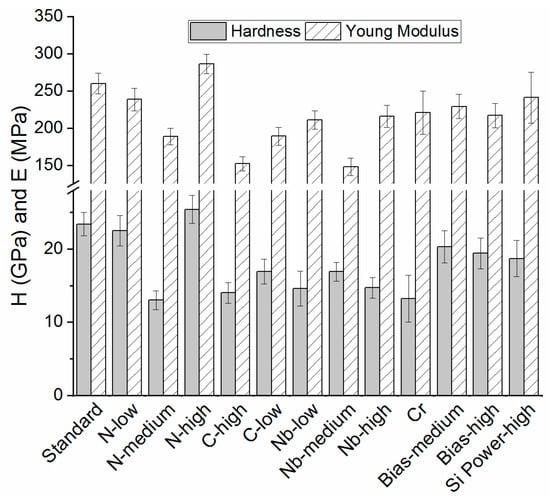
Figure 1.
Hardness and Young’s modulus for SiNx based coatings.
Earlier studies on SiNx coatings have determined similar values for hardness and Young’s modulus, although different deposition methods were applied [39,44,47,63,64]. A higher hardness suggests a higher coating density. Hardness values reported for other coatings for joint implants such as ZrN, TiNbN, Ox-Zr, and TiN coatings resided in a similar range, namely 14.0–31.0, 14.0–24.5 and 12.0–14.0 and 33–56 GPa, respectively [65].
3.4. Adhesion
The scratch test results in terms of Lc2 values are shown in Figure 2. As can be seen, coatings deposited with a higher target power showed lower LC2 values. This was due to higher residual stresses resulting from a higher N content and the increase in Si-N bonds [45,48]. Moreover, these coatings showed a generally denser morphology (data not shown), which in turn contributed to increased residual stresses [66], as demonstrated previously [48]. Furthermore, coatings with higher O and Cr contents displayed higher Lc2 values, which may be related to a lower amount of N-bonds, i.e., an opposite trend to that previously mentioned and/or a decreased coating density and, hence, residual stresses. The following coatings showed statistical differences: Standard vs. C-high, Nb-medium, Nb-high, Bias-medium, Bias-high, and Si power high as well as C-high vs. Nb-medium, Nb-high, Bias-high, and Si power high.
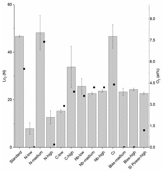
Figure 2.
On the left axis the results for adhesion (Lc2) are shown for the coatings tested in this study, with bars and standard deviations. On the right axis the O2 content of the coatings is shown, represented by square dots.
3.5. Multidirectional Wear Tests
3.5.1. Macroscopic Appearance and Surface Analysis
The macroscopic surface structure of the coatings after the wear tests is shown in Figure 3. The formation of an opaque layer on the surface could be observed during testing on some of the coatings (Figure 3). XPS measurements were, therefore, performed on coating N-medium, at a region that still displayed a reflective surface (assumed to be unworn) and a region that had formed an opaque layer on the surface. Previous work showed a tribofilm formation in aqueous environments for Si3N4 materials, and in those conditions a SiO2 and Si(OH)2 layer could be found, improving the wear resistance and reducing the coefficient of friction by acting as a self-lubricating layer [67,68,69]. However, in the XPS measurements herein the use of charge neutralizers and lack of a good charge reference made the positions of the peeks uncertain. To determine whether the Si2p and O1s peaks originated from Si-O bonds, the distance between the peaks, ΔEb, was determined and compared to the distance (ΔEb) from literature according to Briggs et al. [70]. The deconvoluted Si peaks were fitted with the smallest number of curves possible. The spectrum obtained at the surface revealed contributions attributed to Si-C (100.8 eV), Si-N (101.4 eV), and Si-O (102.8 eV), which correlated well with findings from similar materials. After 2 min sputtering at 500 V the Si-O contribution was no longer detected, while there were still contributions attributed to Si-N and Si-C, and after additional sputtering for 20 min at 1 kV only two contributions were identified, Si-N and Si-Si. These results indicated that the outer layer contained more O and C compared to the bulk of the coating, which could be due to the formation of a tribofilm during wear testing.

Figure 3.
Typical macroscopic appearances of (a) a reacted surface (Standard), (b) a failed coating (Nb-medium), and (c,d) coatings with a surface layer: (c) Coating Cr and (d) coating Si Power-high. In (e) a Bias-high coating is shown, which did not present any layer formation or upcoming failure up to 2 MC.
3.5.2. Coefficient of Friction
Low coefficients of friction were observed for the first 0.5 million cycles for N-high, Standard, Bias-medium, and Bias-high (0.051–0.067). Coatings N-low, Cr, and Si Power-high showed somewhat higher values, from 0.103–0.108, with little variation. Coefficients of friction did not change markedly throughout the tests, except for coatings that reacted or failed during the test (Figure 4). This work generally showed lower coefficients of friction compared to previous work on Nb-Ti-N coatings (ranging from 0.11 to 0.12) and on TiN (0.14) [66].
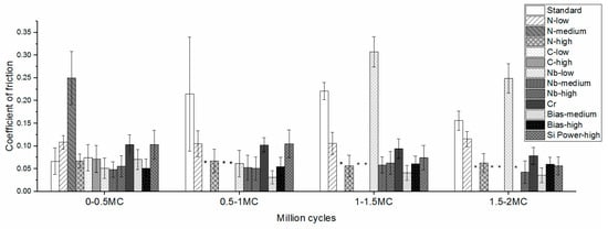
Figure 4.
Coefficient of friction up to 2.0 MC for the tested coatings. During wear tests the following coatings wore through: (*) N-medium, C-high, and C-low at 0.5 MC; Nb-medium at 1.5 MC; Nb-low and Nb-high at 2.0 MC.
3.5.3. Volumetric Wear Rate
While N-low and N-high gave the lowest wear rates for the UHMWPE pins (< 0.37 mm3/MC, Figure 4), N-medium failed already in the first 0.5 MC (Figure 3), giving a high wear rate due to the increased surface roughness from the reacted surface. The Standard coating also gave a high wear rate, due to a reacted surface (Figure 3). The coatings with a higher C content all failed at 0.5 MC. Nb coatings failed at different time points, for example, Nb-low and Nb-high had failed at 2.0 MC and Nb-medium at 1.5 MC. The remaining coatings did not fail and presented low wear rates (0.74–3.63 mm3/MC). Figure 3 and Figure 5 show that coatings with no apparent reaction or coating failure, and that gave low pin wear rates, were those with an initially high hardness (22.5–28.4 GPa), and, hence, presumably higher density and lower reactivity and/or a high N content (N-low, N-high, Bias-medium, Bias-high, and Si Power-high), with the exception being the Standard (H = 23.4 GPa) coating, which, however, contained more oxygen than the well-performing coatings (Table 2), suggesting a higher reactivity. Coating wear through contact with UHMWPE during the tests was not expected, and coatings failing would rather be associated to a higher reactivity and subsequent dissolution [40].
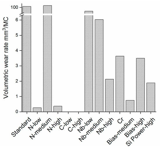
Figure 5.
Volumetric wear rate for the UHMWPE pins ran against all coatings in this study. Coatings C-high and C-low showed negative values of −2.90 and −8.40 mm3/MC, respectively.
4. Conclusions
Based on the results of the coatings tested in this work, some important conclusions were drawn. First, the low-ion energy coatings generally exhibited a lower hardness and initially higher critical load in scratch testing. High concentrations of impurities (higher O content and lower N content) were associated with early reactions and/or dissolution of the coating, as shown by XPS compositional analysis as well as multidirectional wear tests. During the wear tests coatings with lower or no apparent O content did not fail and showed a low volumetric wear rate of UHMWPE pins. SiNx coatings of high N content, low O content (e.g., N-high, Bias-medium, Bias-high, and Si Power-high) are needed for the target–joint implant applications. Promising low wear rates were found for UHWMPE pins sliding against these latter coatings in a multidirectional wear test.
5. Patents
Ionbond AG, where S.S. and M.T. are employees, owns patents related to similar coatings.
Author Contributions
Conceptualization, C.G., M.T., S.S., H.E., H.H., and C.P.; methodology, L.C.F., C.S., M.T., S.S., and C.P.; validation, L.C.F., C.G., C.S., M.T., and S.S.; formal analysis, L.C.F., C.G., C.S., M.T., S.S., and C.P.; investigation, L.C.F., C.G., C.S., M.T., and S.S.; resources, C.P., H.H., and H.E.; writing—original draft preparation, L.C.F., M.T., S.S., and C.P.; writing—review and editing, L.C.F., S.S., C.G., C.S., H.E., M.T., H.H., and C.P.; visualization, L.C.F., S.S., and C.P.; supervision, H.E., H.H., and C.P.; project administration, H.H., H.E., and C.P.; funding acquisition, C.P., H.E., and H.H. All authors have read and agreed to the published version of the manuscript.
Funding
This research was funded by the European Union, grant number FP7-NMP-2012-310477 (Life Long Joints project); EBW+ Project Erasmus Mundus Programme, Action 2–STRAND 1, Lot 9 (Latin America), Brazil, Grant number 2014-0982. H.H. acknowledges financial support from the Swedish Government Strategic Research Area in Materials Science on Advanced Functional Materials at Linköping University (Faculty Grant SFO Mat LiU No. 2009 00971).
Acknowledgments
The authors are grateful for assistance from Mathilde Cogrel and Alejandro López for assistance with MWT measurements.
Conflicts of Interest
The authors declare no conflict of interest, and Ionbond AG, where S.S. and M.T. are employees, owns patents related to similar coatings.
References
- De Bellis, U.G.; Legnani, C.; Calori, G.M. Acute total hip replacement for acetabular fractures: A systematic review of the literature. Injury 2014, 45, 356–361. [Google Scholar] [CrossRef] [PubMed]
- Katz, J.N. Total joint replacement in osteoarthritis. Best Pract. Res. Clin. Rheumatol. 2006, 20, 145–153. [Google Scholar] [CrossRef] [PubMed]
- Salih, S.; Hamer, A. Hip and knee replacement. Surgery 2013, 31, 482–487. [Google Scholar] [CrossRef]
- Shan, L.; Shan, B.; Graham, D.; Saxena, A. Total hip replacement: A systematic review and meta-analysis on mid-term quality of life. Osteoarthr. Cartil. 2014, i22, 389–406. [Google Scholar] [CrossRef] [PubMed]
- Martinez-Cano, J.P.; Herrera-Escobar, J.P.; Arango Gutierrez, A.S.; Sanchez Vergel, A.; Martinez-Rondanelli, A. Prospective quality of life assessment after hip and knee arthroplasty: short- and mid-term follow-up results. Arthroplast. Today 2017. [Google Scholar] [CrossRef] [PubMed]
- Kärrholm, J.; Mohaddes, M.; Odin, D.; Vinblad, J.; Rogmark, C.; Rolfson, O. Swedish Hip Arthroplasty Register Annual Report 2017; Swedish Hip Arthroplasty Register: Göteborg, Swedenm, 2017; ISBN 9789188017208. [Google Scholar]
- Robertsson, O.; W-Dahl, A.; Lidgren, L.; Sundberg, M. Swedish Knee Arthroplasty Register Annual Report 2018; Swedish Hip Arthroplasty Register: Göteborg, Sweden, 2018. [Google Scholar]
- Sharma, V.; Chang, J.-D.; Kim, I.-S.; Yoo, J.-H.; Lee, S.-S.; Mansukhani, S.A. Midterm outcome of fourth-generation ceramic-on-ceramic bearing surfaces in revision total hip arthroplasty. J. Orthop. Surg. 2018, 26, 230949901878391. [Google Scholar] [CrossRef]
- Kurtz, S.M.; Kocagöz, S.; Arnholt, C.; Huet, R.; Ueno, M.; Walter, W.L. Advances in zirconia toughened alumina biomaterials for total joint replacement. J. Mech. Behav. Biomed. Mater. 2014. [Google Scholar] [CrossRef]
- Gamble, D.; Jaiswal, P.K.; Lutz, I.; Johnston, K.D. The Use of Ceramics in Total Hip Arthroplasty. Orthop. Rheumatol. 2017, 4, 1–7. [Google Scholar] [CrossRef]
- Maheshwari, A.V.; Shah, N.V.; Newman, J.M.; Pascal, S.; Sheth, N.P.; Grieco, P.W.; Stroud, S.G. New alternate bearing surfaces in total hip arthroplasty: A review of the current literature. J. Clin. Orthop. Trauma 2017, 9, 7–16. [Google Scholar] [CrossRef]
- Kumar, N.; Arora, N.C.; Datta, B. Bearing surfaces in hip replacement—Evolution and likely future. Med. J. Armed Forces India 2014, 70, 371–376. [Google Scholar] [CrossRef]
- Garrett, S.; Jacobs, N.; Yates, P.; Smith, A.; Wood, D. Differences in metal ion release following cobalt-chromium and oxidized zirconium total knee arthroplasty. Acta Orthop. Belg. 2010, 76, 513–520. [Google Scholar] [PubMed]
- Hui, C.; Salmon, L.; Maeno, S.; Roe, J.; Walsh, W.; Pinczewski, L. Five-Year Comparison of Oxidized Zirconium and Cobalt-Chromium Femoral Components in Total Knee Arthroplasty: A Randomized Controlled Trial. JBJS 2011, 93, 624–630. [Google Scholar] [CrossRef] [PubMed]
- Nowakowski, A.M.; Vavken, P.; Pagenstert, G.; Valderrabano, V. Design, Shape, and Materials of Total Knee Replacement. In The Unhappy Total Knee Replacement: A Comprehensive Review and Management Guide; Hirschmann, M.T., Becker, R., Eds.; Springer International Publishing: Cham, Switzerland, 2015; ISBN 978-3-319-08099-4. [Google Scholar]
- Meier, E.; Gelse, K.; Trieb, K.; Pachowsky, M.; Hennig, F.F.; Mauerer, A. First clinical study of a novel complete metal-free ceramic total knee replacement system. J. Orthop. Surg. Res. 2016, 11, 21. [Google Scholar] [CrossRef]
- Haider, H.; Weisenburger, J.N.; Namavar, F.; Garvin, K.L. Why Coating Technologies for Hip Replacement Systems, and the Importance of Testing Them In Vitro. Oper. Tech. Orthop. 2017, 27, 152–160. [Google Scholar] [CrossRef]
- Wang, Y.X.; Zhang, S. Toward hard yet tough ceramic coatings. Surf. Coat. Technol. 2014, 258, 1–16. [Google Scholar] [CrossRef]
- Breugem, S.J.M.; Linnartz, J.; Sierevelt, I.; Bruijn, J.D.; Driessen, M.J.M. Evaluation of 1031 primary titanium nitride coated mobile bearing total knee arthroplasties in an orthopedic clinic. World J. Orthop. 2017, 8, 922–928. [Google Scholar] [CrossRef]
- Mohammed, A.; Metcalfe, A.; Woodnutt, D. Medium-term outcome of titanium nitride, mobile bearing total knee replacement. Acta Orthop. Belg. 2014, 80, 269–275. [Google Scholar]
- Fabry, C.; Zietz, C.; Baumann, A.; Ehall, R.; Bader, R. High wear resistance of femoral components coated with titanium nitride: a retrieval analysis. Knee Surg. Sport. Traumatol. Arthrosc. 2018, 26, 2630–2639. [Google Scholar] [CrossRef]
- Thomsen, M.; Rozak, M.; Thomas, P. Pain in a chromium-allergic patient with total knee arthroplasty: disappearance of symptoms after revision with a special surface-coated TKA—A case report. Acta Orthop. 2011, 82, 386–388. [Google Scholar] [CrossRef]
- Lützner, J.; Dinnebier, G.; Hartmann, A.; Günther, K.-P.; Kirschner, S. Study rationale and protocol: prospective randomized comparison of metal ion concentrations in the patient’s plasma after implantation of coated and uncoated total knee prostheses. BMC Musculoskelet. Disord. 2009, 10, 128. [Google Scholar] [CrossRef]
- Spector, M.; Ries, M.D.; Bourne, R.B.; Sauer, W.S.; Long, M.; Hunter, G. Wear performance of ultra-high molecular weight polyethylene, on oxidized zirconium total knee femoral components. JBJS 2001, 83, S80–S86. [Google Scholar] [CrossRef] [PubMed]
- Hauert, R.; Thorwarth, K.; Thorwarth, G. An overview on diamond-like carbon coatings in medical applications. Surf. Coat. Technol. 2013. [Google Scholar] [CrossRef]
- Hendry, J.A.; Pilliar, R.M. The fretting corrosion resistance of PVD surface-modified orthopedic implant alloys. J. Biomed. Mater. Res. 2001, 58, 156–166. [Google Scholar] [CrossRef]
- Bader, R.; Bergschmidt, P.; Fritsche, A.; Ansorge, S.; Thomas, P.; Mittelmeier, W. Alternative Werkstoffe und Lösungen in der Knieendoprothetik für Patienten mit Metallallergie. Orthopade 2008, 37, 136–142. [Google Scholar] [CrossRef] [PubMed]
- Alakoski, E.; Tiainen, V.-M.; Soininen, A.; Konttinen, Y.T. Load-Bearing Biomedical Applications of Diamond-Like Carbon Coatings - Current Status. Open Orthop. J. 2008. [Google Scholar] [CrossRef]
- Dearnaley, G.; Arps, J.H. Biomedical applications of diamond-like carbon (DLC) coatings: A review. Surf. Coat. Technol. 2005. [Google Scholar] [CrossRef]
- Maru, M.M.; Amaral, M.; Rodrigues, S.P.; Santos, R.; Gouvea, C.P.; Archanjo, B.S.; Trommer, R.M.; Oliveira, F.J.; Silva, R.F.; Achete, C.A. The High performance of nanocrystalline CVD diamond coated hip joints in wear simulator test. J. Mech. Behav. Biomed. Mater. 2015. [Google Scholar] [CrossRef]
- Pappas, M.J.; Makris, G.; Buechel, F.F. Titanium nitride ceramic film against polyethylene. A 48 million cycle wear test. Clin. Orthop. Relat. Res. 1995, 317, 64–70. [Google Scholar]
- Ching, H.A.; Choudhury, D.; Nine, M.J.; Abu Osman, N.A. Effects of surface coating on reducing friction and wear of orthopaedic implants. Sci. Technol. Adv. Mater. 2014, 15. [Google Scholar] [CrossRef]
- Leslie, I.; Williams, S.; Isaac, G.; Hatto, P.; Ingham, E.; Fisher, J. Wear of surface-engineered metal-onmetal bearings for hip prostheses under adverse conditions with the head loading on the rim of the cup. Proc. Inst. Mech. Eng. Part H J. Eng. Med. 2013. [Google Scholar] [CrossRef]
- Van Hove, R.P.; Sierevelt, I.N.; van Royen, B.J.; Nolte, P.A. Titanium-nitride coating of orthopaedic implants: a review of the literature. Biomed. Res. Int. 2015, 2015, 9. [Google Scholar] [CrossRef] [PubMed]
- Nelissen, R.G.H.H.; Valstar, E.R.; Rozing, P.M. The effect of hydroxyapatite on the micromotion of total knee prostheses. A prospective, randomized, double-blind study. JBJS 1998, 80, 1665–1672. [Google Scholar] [CrossRef] [PubMed]
- Bal, B.S.; Rahaman, M.N. Orthopedic applications of silicon nitride ceramics. Acta Biomater. 2012, 8, 2889–2898. [Google Scholar] [CrossRef] [PubMed]
- Bock, R.M.; McEntire, B.J.; Bal, B.S.; Rahaman, M.N.; Boffelli, M.; Pezzotti, G. Surface modulation of silicon nitride ceramics for orthopaedic applications. Acta Biomater. 2015. [Google Scholar] [CrossRef]
- Pettersson, M.; Bryant, M.; Schmidt, S.; Engqvist, H.; Hall, R.M.; Neville, A.; Persson, C. Dissolution behaviour of silicon nitride coatings for joint replacements. Mater. Sci. Eng. C 2016, 62, 497–505. [Google Scholar] [CrossRef]
- Pettersson, M.; Tkachenko, S.; Schmidt, S.; Berlind, T.; Jacobson, S.; Hultman, L.; Engqvist, H.; Persson, C. Mechanical and tribological behavior of silicon nitride and silicon carbon nitride coatings for total joint replacements. J. Mech. Behav. Biomed. Mater. 2013, 25, 41–47. [Google Scholar] [CrossRef]
- Filho, L.C.; Schmidt, S.; López, A.; Cogrel, M.; Leifer, K.; Engqvist, H.; Högberg, H.; Persson, C. The Effect of Coating Density on Functional Properties of SiN(x) Coated Implants. Materials 2019, 12, 3370. [Google Scholar] [CrossRef]
- Lee, J.-W.; Chang, Y.-C. A study on the microstructures and mechanical properties of pulsed DC reactive magnetron sputtered Cr-Si-N nanocomposite coatings. Surf. Coat. Technol. 2007, 202, 831–836. [Google Scholar] [CrossRef]
- Park, J.H.; Chung, W.S.; Cho, Y.-R.; Kim, K.H. Synthesis and mechanical properties of Cr-Si-N coatings deposited by a hybrid system of arc ion plating and sputtering techniques. Surf. Coat. Technol. 2004, 188, 425–430. [Google Scholar] [CrossRef]
- Hones, P.; Sanjines, R.; Lévy, F. Sputter deposited chromium nitride based ternary compounds for hard coatings. Thin Solid Films 1998, 332, 240–246. [Google Scholar] [CrossRef]
- Olofsson, J.; Pettersson, M.; Teuscher, N.; Heilmann, A.; Larsson, K.; Grandfield, K.; Persson, C.; Jacobson, S.; Engqvist, H. Fabrication and evaluation of SixNy coatings for total joint replacements. J. Mater. Sci. Mater. Med. 2012, 23, 1879–1889. [Google Scholar] [CrossRef] [PubMed]
- Hänninen, T.; Schmidt, S.; Ivanov, I.G.; Jensen, J.; Hultman, L.; Högberg, H. Silicon carbonitride thin films deposited by reactive high power impulse magnetron sputtering. Surf. Coat. Technol. 2018, 335, 248–256. [Google Scholar] [CrossRef]
- Skjöldebrand, C.; Schmidt, S.; Vuong, V.; Pettersson, M.; Grandfield, K.; Högberg, H.; Engqvist, H.; Persson, C. Influence of substrate heating and nitrogen flow on the composition, morphological and mechanical properties of SiNx coatings aimed for joint replacements. Materials 2017, 10, 173. [Google Scholar] [CrossRef] [PubMed]
- Schmidt, S.; Hänninen, T.; Goyenola, C.; Wissting, J.; Jensen, J.; Hultman, L.; Goebbels, N.; Tobler, M.; Högberg, H. SiN x Coatings Deposited by Reactive High Power Impulse Magnetron Sputtering: Process Parameters Influencing the Nitrogen Content. ACS Appl. Mater. Interfaces 2016. [Google Scholar] [CrossRef] [PubMed]
- Schmidt, S.; Hänninen, T.; Wissting, J.; Hultman, L.; Goebbels, N.; Santana, A.; Tobler, M.; Högberg, H. SiNx coatings deposited by reactive high power impulse magnetron sputtering: Process parameters influencing the residual coating stress. J. Appl. Phys. 2017, 121, 171904. [Google Scholar] [CrossRef]
- Hofmann, S. Auger- and X-ray Photoelectron Spectroscopy in Materials Science: A User-Oriented Guide; Springer Science & Business Media: Berlin/Heidelberg, Germany, 2012; Volume 49. [Google Scholar]
- Oliver, W. Improved technique for determining hardness and elastic modulus using load and displacement sensing indentation experiments. J. Mater. Res. 1992. [Google Scholar] [CrossRef]
- ISO 20502:2005. Fine Ceramics (Advanced Ceramics, Advanced Technical Ceramics)—Determination of Adhesion of Ceramic Coatings by Scratch Testing; ISO: Geneva, Switzerland, 2005. [Google Scholar]
- Hassan, M.A.; Bushroa, A.R.; Mahmoodian, R. Identification of critical load for scratch adhesion strength of nitride-based thin films using wavelet analysis and a proposed analytical model. Surf. Coat. Technol. 2015, 277, 216–221. [Google Scholar] [CrossRef]
- Beake, B.D.; Vishnyakov, V.M.; Valizadeh, R.; Colligon, J.S. Influence of mechanical properties on the nanoscratch behaviour of hard nanocomposite TiN/Si3N4 coatings on Si. J. Phys. D. Appl. Phys. 2006, 39, 1392. [Google Scholar] [CrossRef]
- ISO 5834-2:2019. Implants for Surgery—Ultra-High-Molecular-Weight Polyethylene—Part 2: Moulded Forms; ISO: Geneva, Switzerland, 2019. [Google Scholar]
- ASTM. ASTM F2025-06(2018), Standard Practice for Gravimetric Measurement of Polymeric Components for Wear Assessment; ASTM International: West Conshohocken, PA, USA, 2018. [Google Scholar] [CrossRef]
- ASTM. ASTM F732-17, Standard Test Method for Wear Testing of Polymeric Materials Used in Total Joint Prostheses; ASTM International: West Conshohocken, PA, USA, 2017. [Google Scholar]
- Wasa, K.; Hayakawa, S. Handbook of Sputter Deposition Technology; IAEA: Vienna, Austria, 1992. [Google Scholar]
- Gu, J.; Li, L.; Miao, H.; Xu, Y.; Xu, Y.; Sun, J.; Wang, X.; He, Z. Effect of C2H2/N2 partial pressure ratio on microstructure and mechanical properties of Ti-Al-Si-C-N coatings. Surf. Coat. Technol. 2019, 365, 200–207. [Google Scholar] [CrossRef]
- Huang, S.W.; Ng, M.W.; Samandi, M.; Brandt, M. Tribological behaviour and microstructure of TiCxN(1−x) coatings deposited by filtered arc. Wear 2002, 252, 566–579. [Google Scholar] [CrossRef]
- Guo, C.; Li, M.; Nibarger, J.P.; Gibson, G.N. Single and double ionization of diatomic molecules in strong laser fields. Phys. Rev. A 1998, 58, R4271–R4274. [Google Scholar] [CrossRef]
- Sorensen, S.L.; Björneholm, O.; Hjelte, I.; Kihlgren, T.; Öhrwall, G.; Sundin, S.; Svensson, S.; Buil, S.; Descamps, D.; L’Huillier, A.; et al. Femtosecond pump-probe photoelectron spectroscopy of predissociative Rydberg states in acetylene. J. Chem. Phys. 2000, 112, 8038–8042. [Google Scholar] [CrossRef][Green Version]
- Reutt, J.E.; Wang, L.S.; Pollard, J.E.; Trevor, D.J.; Lee, Y.T.; Shirley, D.A. Photoelectron spectroscopy and inferred femtosecond intramolecular dynamics of C2H2+ and C2D2+. J. Chem. Phys. 1986, 84, 3022–3031. [Google Scholar] [CrossRef]
- Pusch, C.; Hoche, H.; Berger, C.; Riedel, R.; Ionescu, E.; Klein, A. Influence of the PVD sputtering method on structural characteristics of SiCN-coatings—Comparison of RF, DC and HiPIMS sputtering and target configurations. Surf. Coat. Technol. 2011, 205, S119–S123. [Google Scholar]
- Shi, Z.; Wang, Y.; Du, C.; Huang, N.; Wang, L.; Ning, C. Silicon nitride films for the protective functional coating: blood compatibility and biomechanical property study. J. Mech. Behav. Biomed. Mater. 2012, 16, 9–20. [Google Scholar] [PubMed]
- McEntire, B.J.; Bal, B.S.; Rahaman, M.N.; Chevalier, J.; Pezzotti, G. Ceramics and ceramic coatings in orthopaedics. J. Eur. Ceram. Soc. 2015, 35, 4327–4369. [Google Scholar]
- Dumitriu La Grange, D.; Goebbels, N.; Santana, A.; Heuberger, R.; Imwinkelried, T.; Eschbach, L.; Karimi, A. Effect of niobium onto the tribological behavior of cathodic arc deposited Nb-Ti-N coatings. Wear 2016, 368–369. [Google Scholar] [CrossRef]
- Park, I.-W.; Kang, D.S.; Moore, J.J.; Kwon, S.C.; Rha, J.J.; Kim, K.H. Microstructures, mechanical properties, and tribological behaviors of Cr–Al–N, Cr–Si–N, and Cr–Al–Si–N coatings by a hybrid coating system. Surf. Coat. Technol. 2007, 201, 5223–5227. [Google Scholar] [CrossRef]
- Xu, J.; Kato, K. Formation of tribochemical layer of ceramics sliding in water and its role for low friction. Wear 2000, 245, 61–75. [Google Scholar] [CrossRef]
- Dante, R.C.; Kajdas, C.K. A review and a fundamental theory of silicon nitride tribochemistry. Wear 2012. [Google Scholar] [CrossRef]
- Briggs, D. Handbook of X-ray Photoelectron Spectroscopy; Wanger, C.D., Riggs, W.M., Davis, L.E., Moulder, J.F., Muilenberg, G.E., Eds.; Perkin-Elmer Corp., Physical Electronics Division: Eden Prairie, MN, USA, 1979; pp. 190–195. [Google Scholar]


© 2020 by the authors. Licensee MDPI, Basel, Switzerland. This article is an open access article distributed under the terms and conditions of the Creative Commons Attribution (CC BY) license (http://creativecommons.org/licenses/by/4.0/).