Survival Probability, Weibull Characteristics, Stress Distribution, and Fractographic Analysis of Polymer-Infiltrated Ceramic Network Restorations Cemented on a Chairside Titanium Base: An In Vitro and In Silico Study

 ,
,  ,
,  ,
, 
Abstract
1. Introduction
2. Materials and Methods
2.1. Specimens Preparations
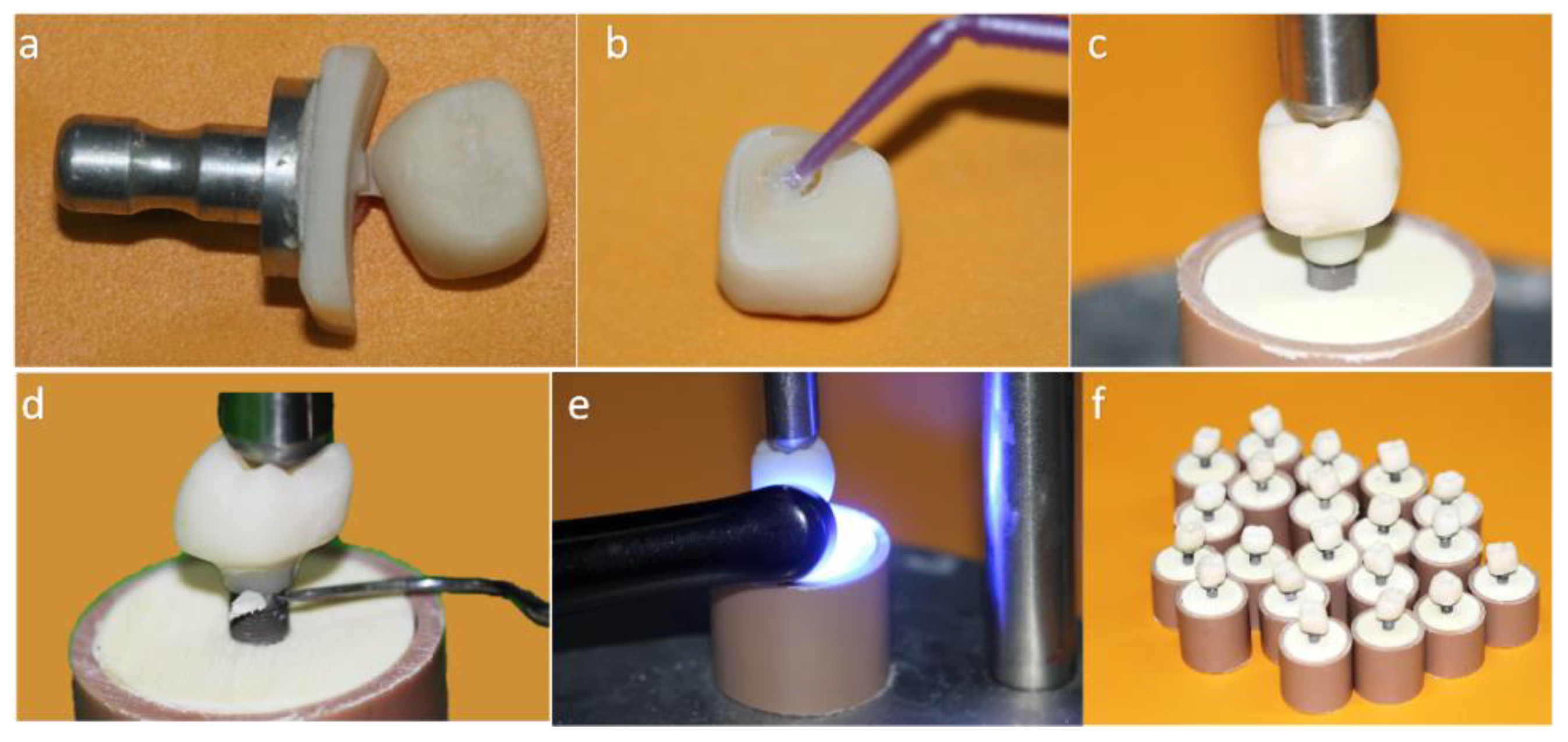
2.1.1. Crown Cemented on a Mesostructure (CME) Prosthesis Design: Two-Piece Prosthetic Solution Composed by a Crown Cemented on the Hybrid Abutment
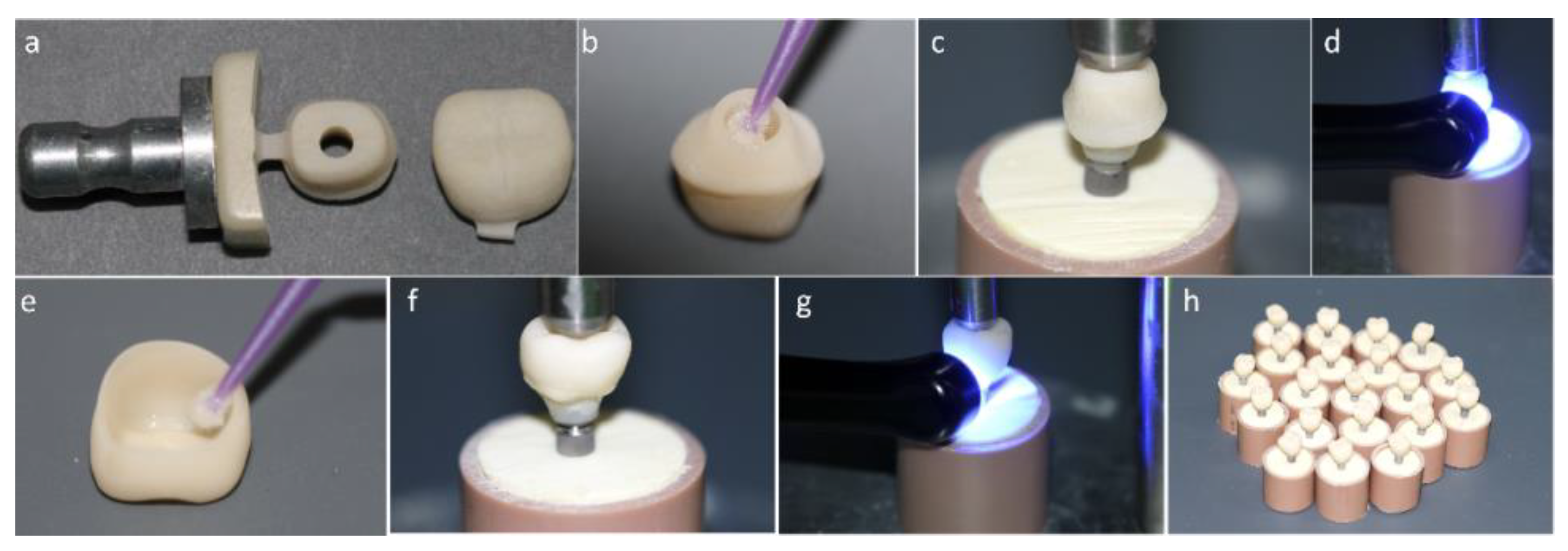
2.1.2. Monolithic Crown (MC) Prosthesis Design: One-Piece Prosthetic Solution Composed by a Crown Direct Cemented on a Titanium Base
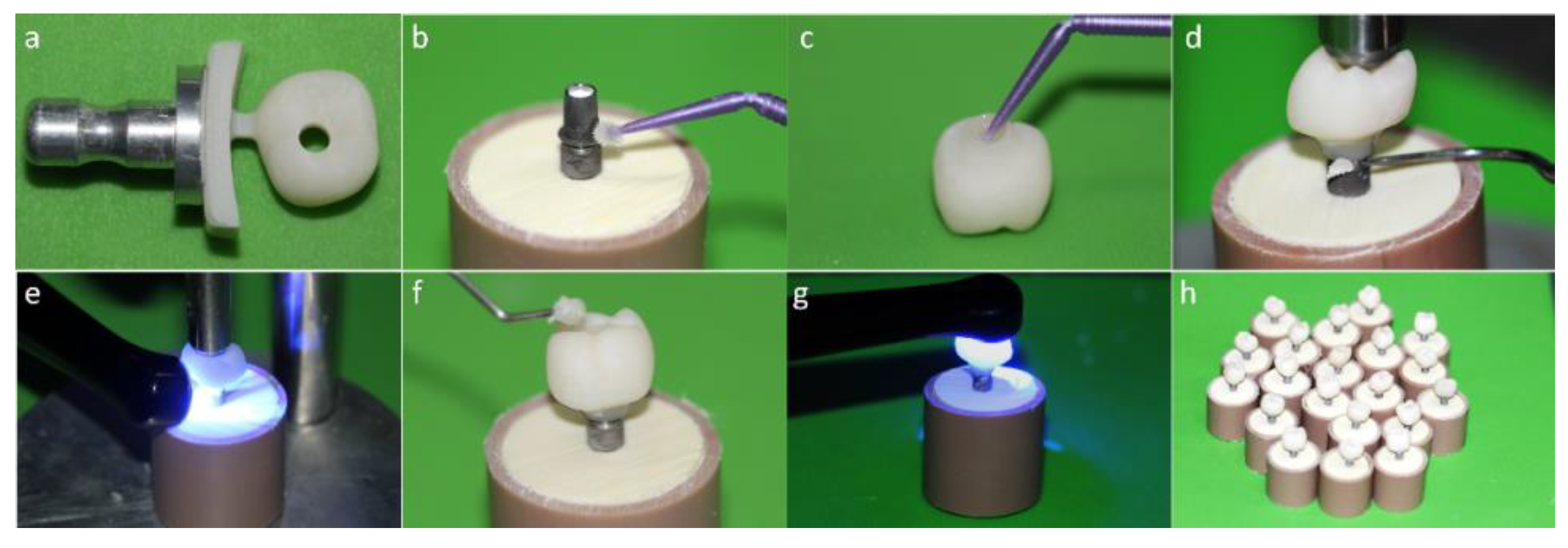
2.1.3. MP Prosthesis Design: One-Piece Prosthetic Solution Composed by a Crown Cemented on a Tibase with Screw Access Hole
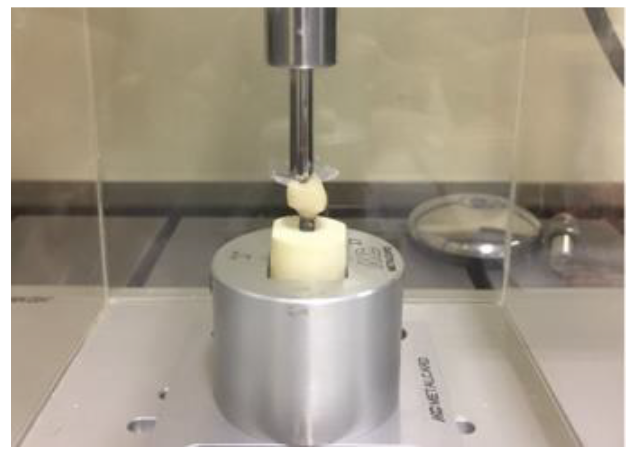
2.2. Fatigue Test
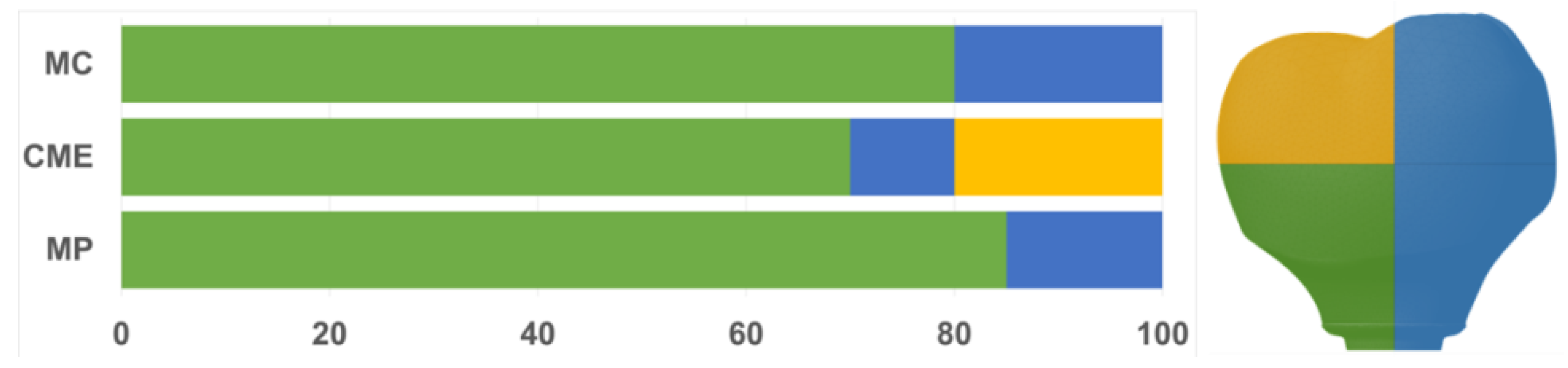
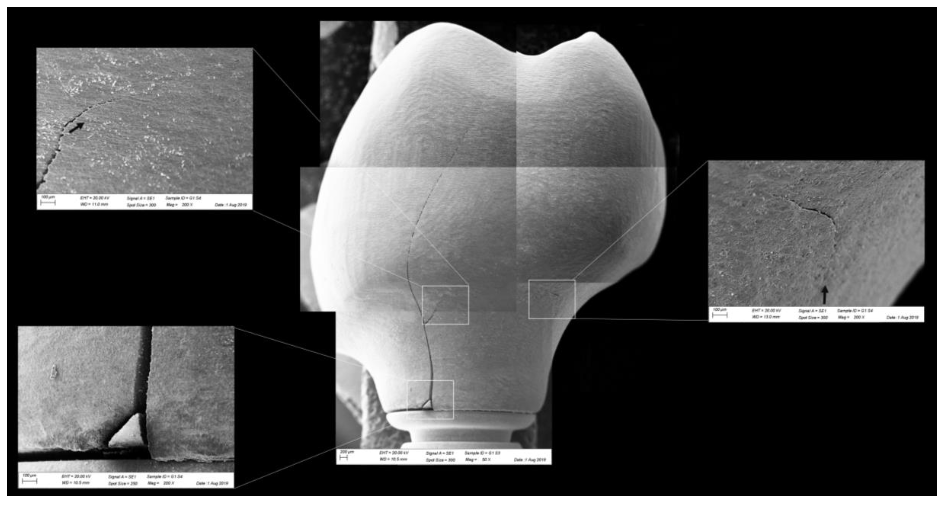
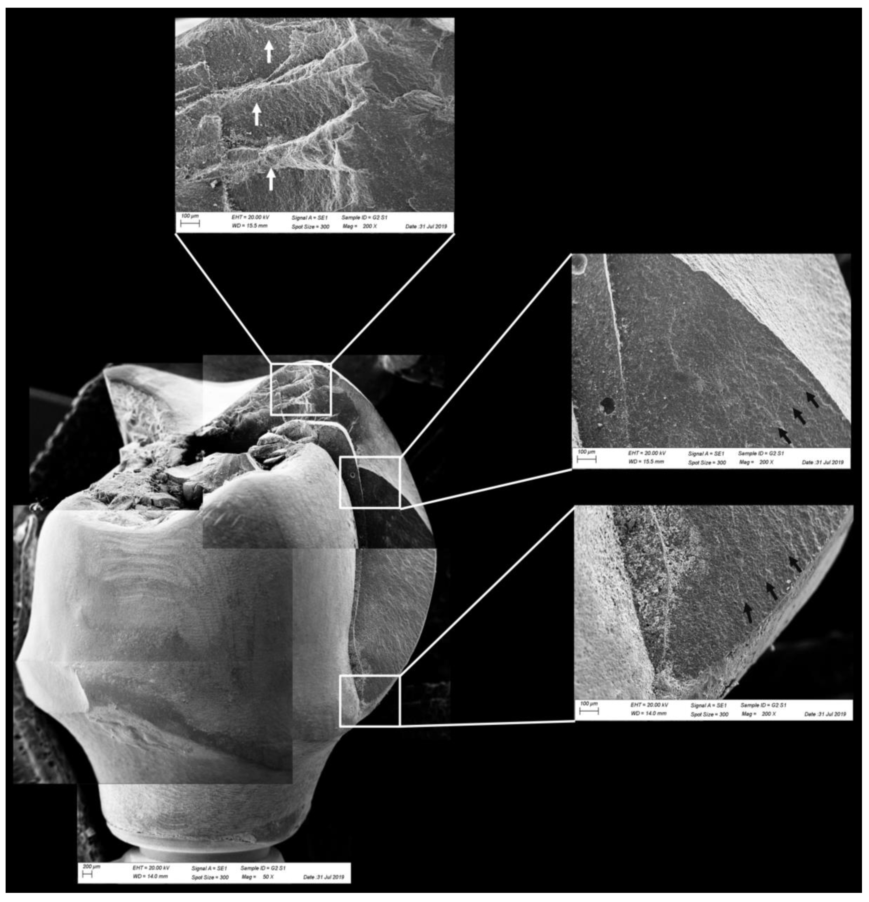
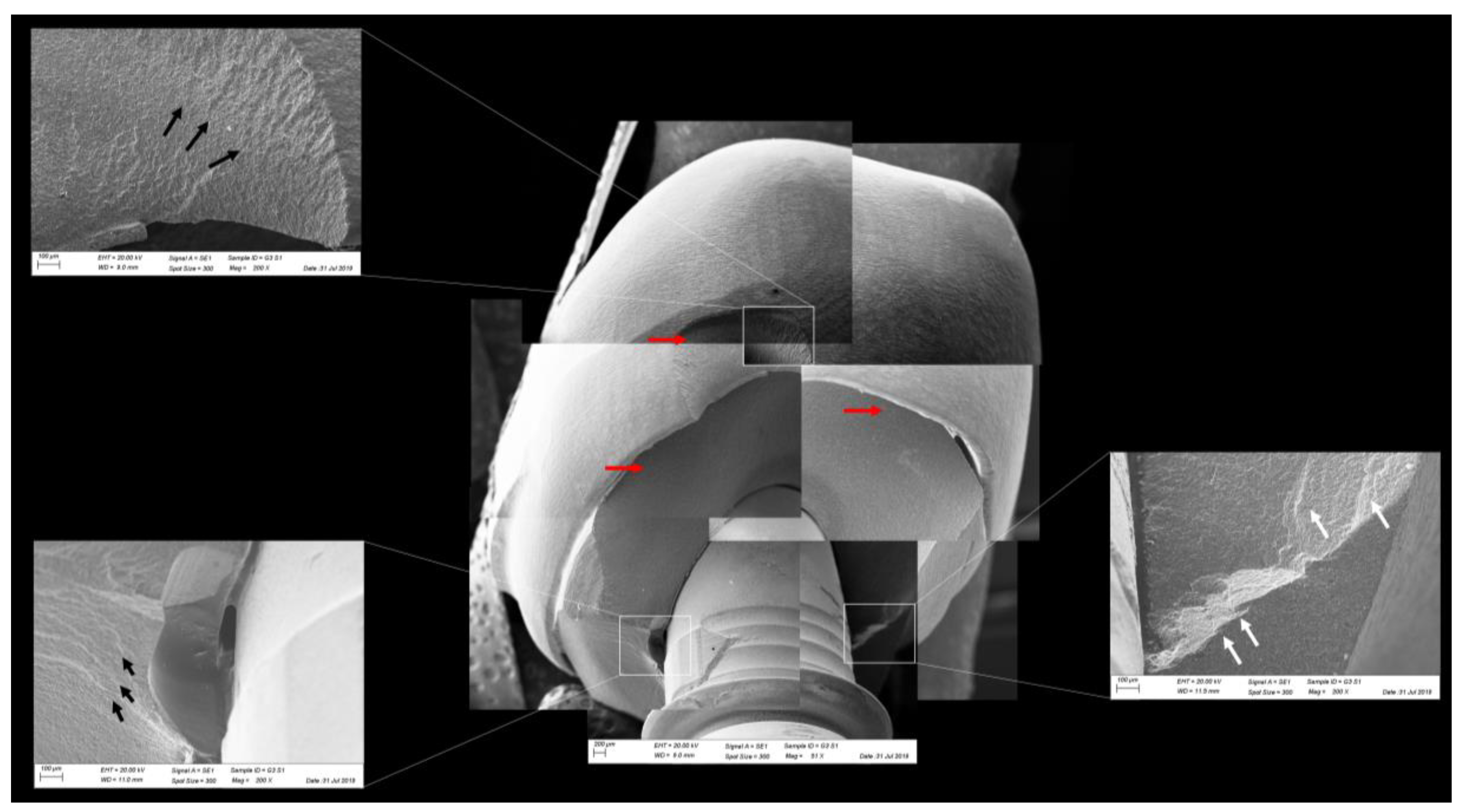
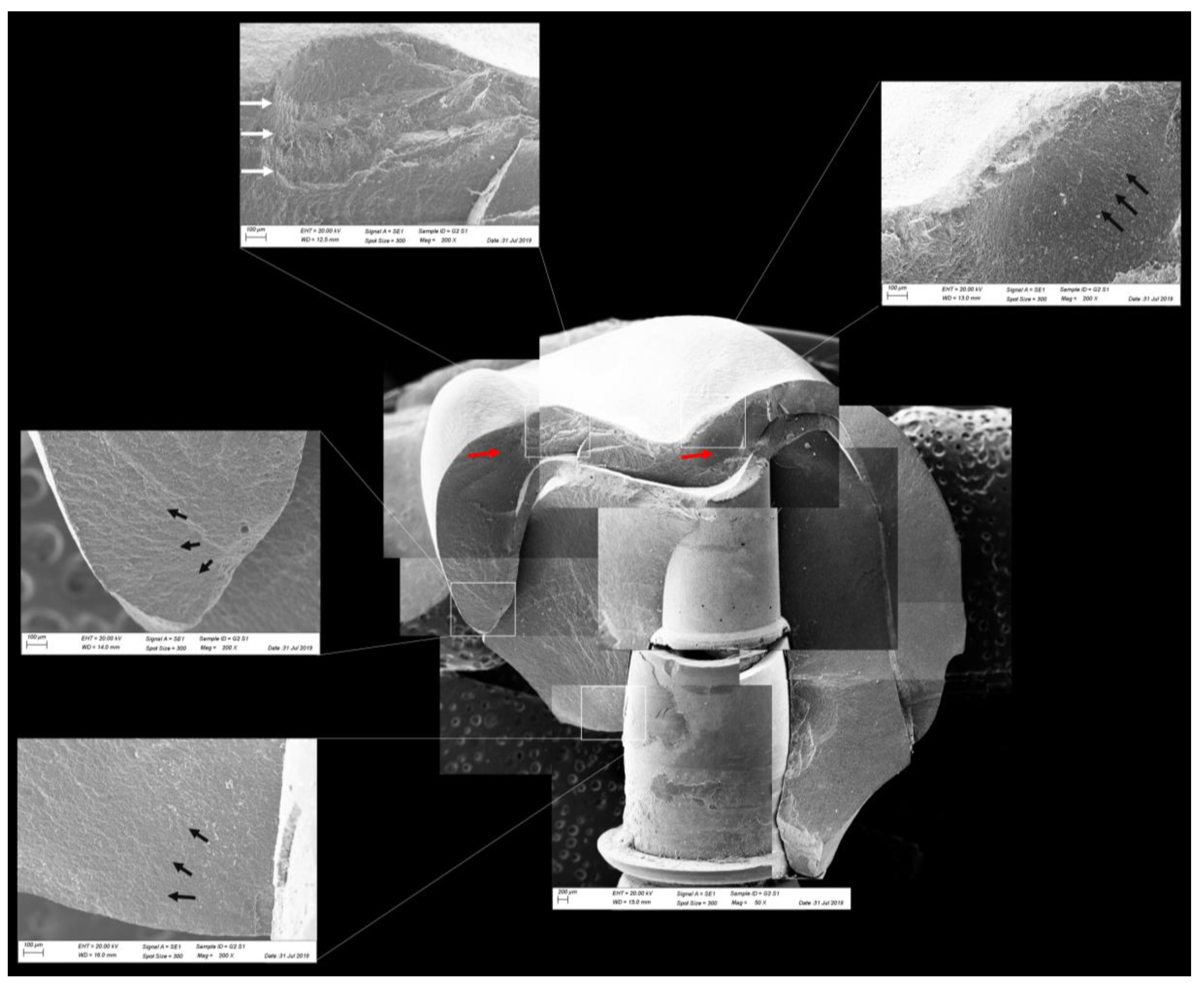
2.3. Fractographic Analysis
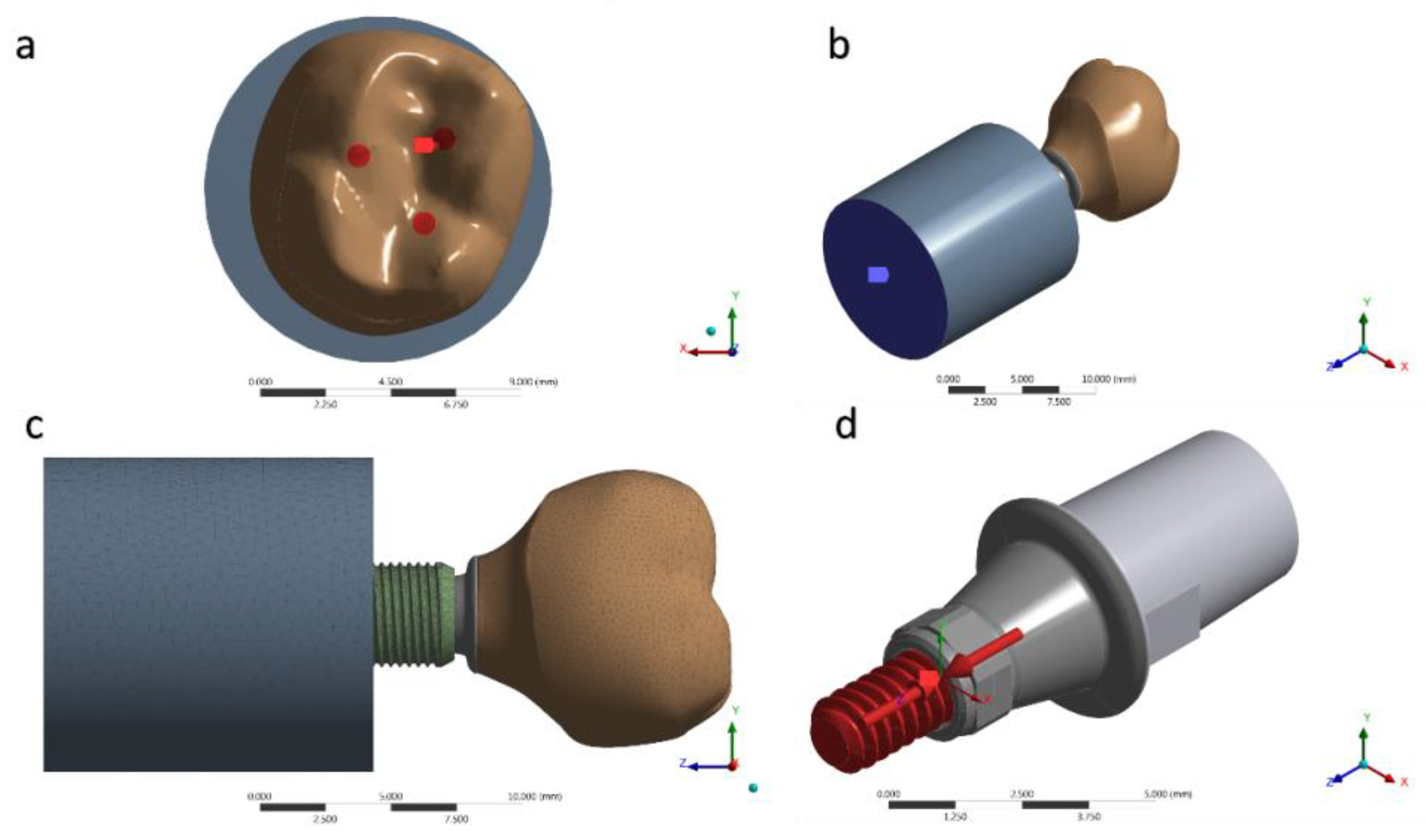
2.4. Nonlinear Finite Element Analysis
2.5. Data Analysis
3. Results
3.1. Fatigue Test
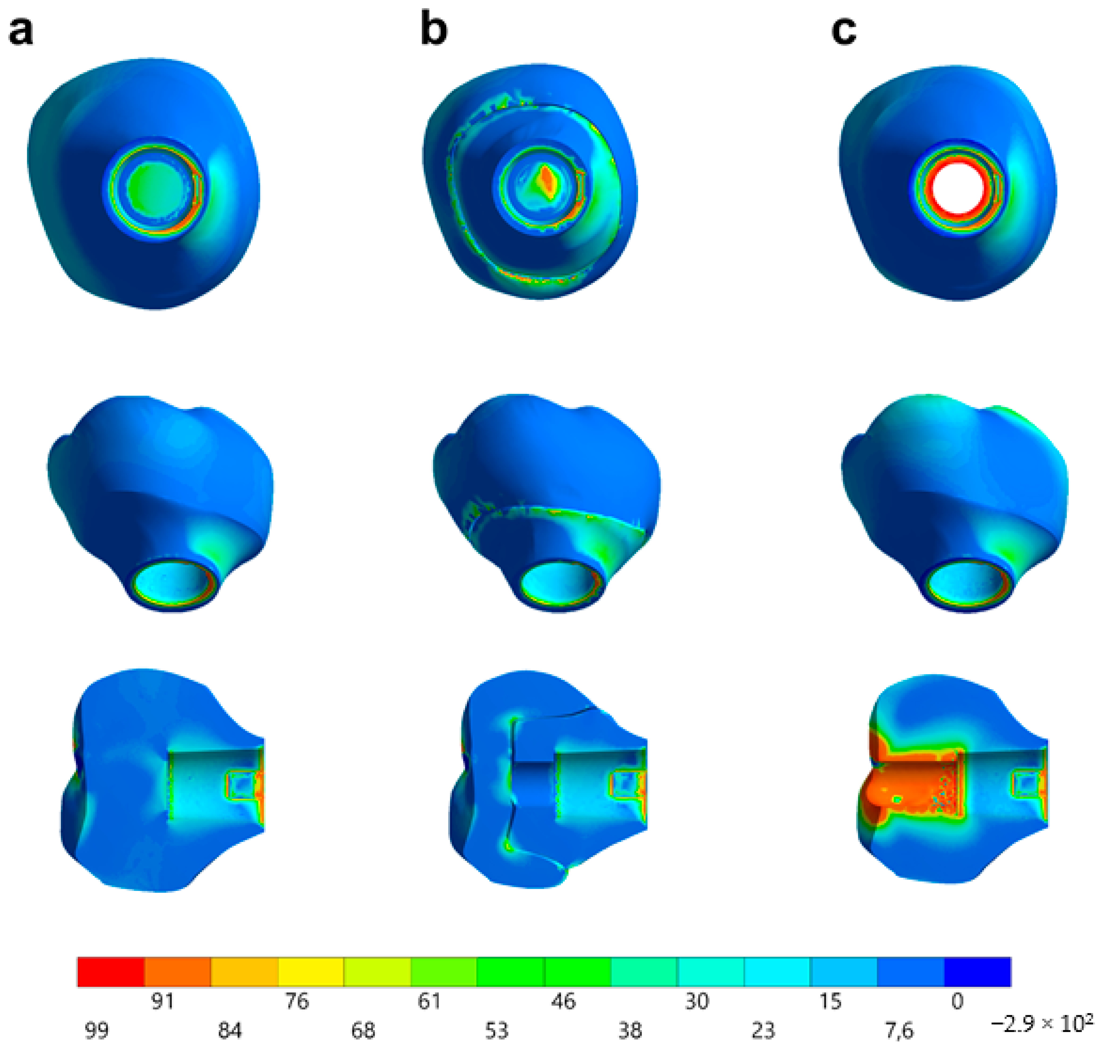
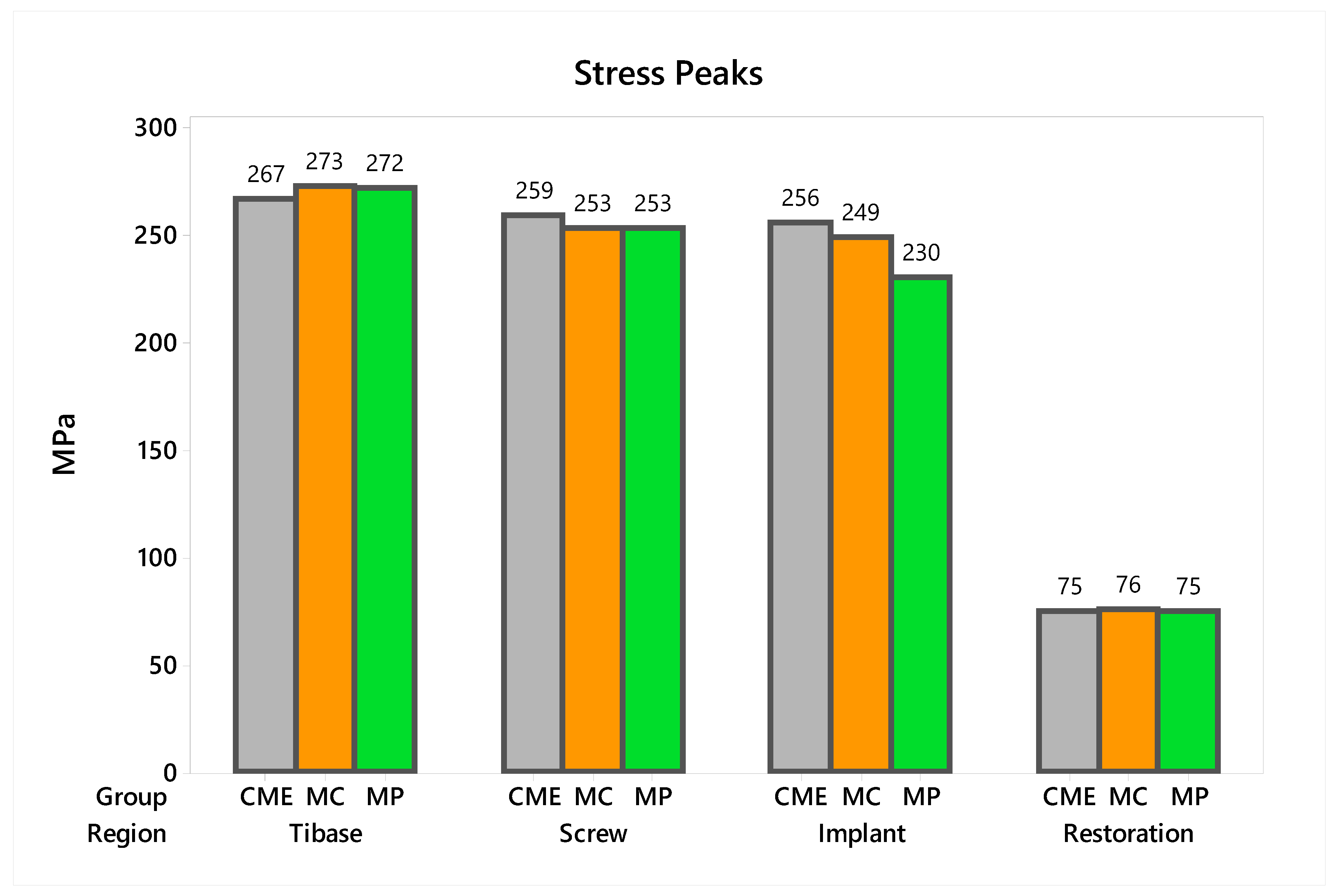
3.2. Nonlinear Finite Element Analysis
4. Discussion
5. Conclusions
Author Contributions
Funding
Acknowledgments
Conflicts of Interest
References
- Sagsoz, O.; Demirci, T.; Demirci, G.; Sagsoz, N.P.; Yildiz, M. The effects of different polishing techniques on the staining resistance of CAD/CAM resin-ceramics. J. Adv. Prosthodont. 2016, 8, 417–422. [Google Scholar] [CrossRef] [PubMed]
- Coldea, A.; Swain, M.V.; Thiel, N. Mechanical properties of polymer-infiltrated-ceramic-network materials. Dent. Mater. 2013, 29, 419–426. [Google Scholar] [CrossRef] [PubMed]
- Conrad, H.J.; Seong, W.-J.; Pesun, I.J. Current ceramic materials and systems with clinical recommendations: A systematic review. J. Prosthet. Dent. 2007, 98, 389–404. [Google Scholar] [CrossRef]
- Denry, I.; Kelly, J. Emerging ceramic-based materials for dentistry. J. Dent. Res. 2014, 93, 1235–1242. [Google Scholar] [CrossRef]
- Ramos, N.D.C.; Campos, T.M.B.; De La Paz, I.S.; Machado, J.P.B.; Bottino, M.A.; Cesar, P.F.; Melo, R. Microstructure characterization and SCG of newly engineered dental ceramics. Dent. Mater. 2016, 32, 870–878. [Google Scholar] [CrossRef]
- Curran, P.; Cattani-Lorente, M.; Wiskott, H.W.A.; Durual, S.; Scherrer, S.S. Grinding damage assessment for CAD-CAM restorative materials. Dent. Mater. 2017, 33, 294–308. [Google Scholar] [CrossRef]
- Goujat, A.; Abouelleil, H.; Colon, P.; Jeannin, C.; Pradelle, N.; Seux, D.; Grosgogeat, B. Mechanical properties and internal fit of 4 CAD-CAM block materials. J. Prosthet. Dent. 2017, 119, 384–389. [Google Scholar] [CrossRef]
- Awada, A.; Nathanson, D. Mechanical properties of resin-ceramic CAD/CAM restorative materials. J. Prosthet. Dent. 2015, 114, 587–593. [Google Scholar] [CrossRef]
- Della Bona, A.; Corazza, P.H.; Zhang, Y. Characterization of a polymer-infiltrated ceramic-network material. Dent. Mater. 2014, 30, 564–569. [Google Scholar] [CrossRef]
- Gracis, S.; Thompson, V.P.; Ferencz, J.L.; Silva, N.R.; Bonfante, E.A. A new classification system for all-ceramic and ceramic-like restorative materials. Int. J. Prosthodont. 2015, 28, 227–235. [Google Scholar] [CrossRef]
- Dirxen, C.; Blunck, U.; Preissner, R. Clinical Performance of a New Biomimetic Double Network Material. Open Dent. J. 2013, 7, 118–122. [Google Scholar] [CrossRef] [PubMed]
- Homaei, E.; Farhangdoost, K.; Tsoi, J.K.-H.; Matinlinna, J.P.; Pow, E.H.N. Static and fatigue mechanical behavior of three dental CAD/CAM ceramics. J. Mech. Behav. Biomed. Mater. 2016, 59, 304–313. [Google Scholar] [CrossRef] [PubMed]
- De Kok, P.; Kleverlaan, C.J.; De Jager, N.; Kuijs, R.; Feilzer, A.J. Mechanical performance of implant-supported posterior crowns. J. Prosthet. Dent. 2015, 114, 59–66. [Google Scholar] [CrossRef] [PubMed]
- Peampring, C. Restorative management using hybrid ceramic of a patient with severe tooth erosion from swimming: A clinical report. J. Adv. Prosthodont. 2014, 6, 423–426. [Google Scholar] [CrossRef] [PubMed]
- Kurbad, A. Final restoration of implants with a hybrid ceramic superstructure. Int. J. Comput. Dent. 2016, 19, 257–279. [Google Scholar]
- Bonfante, E.A.; Suzuki, M.; Lorenzoni, F.C.; Sena, L.A.; Hirata, R.; Bonfante, G.; Coelho, P.G. Probability of survival of implant-supported metal ceramic and CAD/CAM resin nanoceramic crowns. Dent. Mater. 2015, 31, e168–e177. [Google Scholar] [CrossRef]
- Glauser, R.; Sailer, I.; Wohlwend, A.; Studer, S.; Schibli, M.; Schärer, P. Experimental zirconia abutments for implant-supported single-tooth restorations in esthetically demanding regions: 4-year results of a prospective clinical study. Int. J. Prosthodont. 2004, 17, 285–290. [Google Scholar]
- Aboushelib, M.N.; Salameh, Z. Zirconia implant abutment fracture: Clinical case reports and precautions for use. Int. J. Prosthodont. 2009, 22, 616–619. [Google Scholar]
- Prestipino, V.; Ingber, A. All-Ceramic Implant Abutments: Esthetic Indications. J. Esthet. Restor. Dent. 1996, 8, 255–262. [Google Scholar] [CrossRef]
- Elsayed, A.; Wille, S.; Al-Akhali, M.; Kern, M. Comparison of fracture strength and failure mode of different ceramic implant abutments. J. Prosthet. Dent. 2017, 117, 499–506. [Google Scholar] [CrossRef]
- Elsayed, A.; Wille, S.; Al-Akhali, M.; Kern, M. Effect of fatigue loading on the fracture strength and failure mode of lithium disilicate and zirconia implant abutments. Clin. Oral Implant. Res. 2017, 29, 20–27. [Google Scholar] [CrossRef] [PubMed]
- Tribst, J.P.M.; Piva, A.M.D.O.D.; Borges, A.L.S.; Bottino, M.A. Influence of crown and hybrid abutment ceramic materials on the stress distribution of implant-supported prosthesis. Rev. de Odontol. da UNESP 2018, 47, 149–154. [Google Scholar] [CrossRef]
- Tribst, J.P.M.; Piva, A.M.D.O.D.; Borges, A.L.S.; Bottino, M.A. Different combinations of CAD/CAM materials on the biomechanical behavior of a two-piece prosthetic solution. Int. J. Comput. Dent. 2019, 22, 171–176. [Google Scholar] [PubMed]
- Tribst, J.P.M.; Piva, A.M.O.D.; Özcan, M.; Borges, A.L.S.; Bottino, M.A. Influence of Ceramic Materials on Biomechanical Behavior of Implant Supported Fixed Prosthesis with Hybrid Abutment. Eur. J. Prosthodont. Restor. Dent. 2019, 27, 76–82. [Google Scholar] [PubMed]
- Tribst, J.P.M.; Piva, A.M.D.O.D.; Anami, L.C.; Borges, A.L.S.; Bottino, M. A Influence of implant connection on the stress distribution in restorations performed with hybrid abutments. J. Osseointegration 2019, 11, 507–512. [Google Scholar]
- Nouh, I.; Kern, M.; Sabet, A.E.; AboelFadl, A.K.; Hamdy, A.M.; Chaar, M.S. Mechanical behavior of posterior all-ceramic hybrid-abutment-crowns versus hybrid-abutments with separate crowns-A laboratory study. Clin. Oral Implant. Res. 2018, 30, 90–98. [Google Scholar] [CrossRef]
- Roberts, E.E.; Bailey, C.W.; Ashcraft-Olmscheid, D.L.; Vandewalle, K.S. Fracture Resistance of Titanium-Based Lithium Disilicate and Zirconia Implant Restorations. J. Prosthodont. 2018, 27, 644–650. [Google Scholar] [CrossRef]
- Edelhoff, D.; Schweiger, J.; Prandtner, O.; Stimmelmayr, M.; Güth, J.-F. Metal-free implant-supported single-tooth restorations. Part I: Abutments and cemented crowns. Quintessence Int. 2019, 50, 176–184. [Google Scholar]
- Øilo, M.; Arola, D. Fractographic analyses of failed one-piece zirconia implant restorations. Dent. Mater. 2018, 34, 922–931. [Google Scholar] [CrossRef]
- Scherrer, S.S.; Cattani-Lorente, M.; Vittecoq, E.; De Mestral, F.; Griggs, J.A.; Wiskott, H.A. Fatigue behavior in water of Y-TZP zirconia ceramics after abrasion with 30μm silica-coated alumina particles. Dent. Mater. 2010, 27, e28–e42. [Google Scholar] [CrossRef]
- De Melo, R.M.; Pereira, C.; Ramos, N.D.C.; Feitosa, F.; Piva, A.M.D.O.D.; Tribst, J.P.M.; Ozcan, M.; Jorge, A.O.C.; Özcan, M. Effect of pH variation on the subcritical crack growth parameters of glassy matrix ceramics. Int. J. Appl. Ceram. Technol. 2019, 16, 2449–2456. [Google Scholar] [CrossRef]
- Miyashiro, M.; Suedam, V.; Neto, R.T.M.; Ferreira, P.M.; Rubo, J.H. Validation of an experimental polyurethane model for biomechanical studies on implant supported prosthesis - tension tests. J. Appl. Oral Sci. 2011, 19, 244–248. [Google Scholar] [CrossRef] [PubMed]
- Ramos, G.F.; Monteiro, E.; Bottino, M.; Zhang, Y.; De Melo, R.M.; Bottino, M.A. Failure probability of three designs of zirconia crowns. Int. J. Periodontics Restor. Dent. 2015, 35, 843–849. [Google Scholar] [CrossRef] [PubMed]
- Anami, L.C.; Lima, J.; Valandro, L.F.; Kleverlaan, C.; Feilzer, A.; Bottino, M.A. Fatigue Resistance of Y-TZP/Porcelain Crowns is Not Influenced by the Conditioning of the Intaglio Surface. Oper. Dent. 2016, 41, E1–E12. [Google Scholar] [CrossRef]
- Bottino, M.A.; Rocha, R.F.V.; Anami, L.C.; Özcan, M.; Melo, R.M. Fracture of Zirconia Abutment with Metallic Insertion on Anterior Single Titanium Implant with Internal Hexagon: Retrieval Analysis of a Failure. Eur. J. Prosthodont. Restor. Dent. 2016, 24, 164–168. [Google Scholar]
- Idogava, H.T.; Noritomi, P.Y.; Daniel, G.B. Numerical model proposed for a temporomandibular joint prosthesis based on the recovery of the healthy movement. Comput. Methods Biomech. Biomed. Eng. 2018, 21, 1–9. [Google Scholar] [CrossRef]
- Alkan, I.; Sertgöz, A.; Ekici, B. Influence of occlusal forces on stress distribution in preloaded dental implant screws. J. Prosthet. Dent. 2004, 91, 319–325. [Google Scholar] [CrossRef]
- Tribst, J.P.M.; Piva, A.M.D.O.D.; De Melo, R.M.; Borges, A.L.S.; Bottino, M.A.; Ozcan, M. Short communication: Influence of restorative material and cement on the stress distribution of posterior resin-bonded fixed dental prostheses: 3D finite element analysis. J. Mech. Behav. Biomed. Mater. 2019, 96, 279–284. [Google Scholar] [CrossRef]
- Benzing, U.R.; Gall, H.; Weber, H. Biomechanical aspects of two different implant-prosthetic concepts for edentulous maxillae. Int. J. Oral Maxillofac. Implant. 1995, 10, 188–198. [Google Scholar]
- Souza, A.; Xavier, T.; Platt, J.; Borges, A.L.S. Effect of Base and Inlay Restorative Material on the Stress Distribution and Fracture Resistance of Weakened Premolars. Oper. Dent. 2015, 40, 158–166. [Google Scholar] [CrossRef]
- Singh, S.V.; Gupta, S.; Sharma, D.; Pandit, N.; Nangom, A.; Satija, H. Stress distribution of posts on the endodontically treated teeth with and without bone height augmentation: A three-dimensional finite element analysis. J. Conserv. Dent. 2015, 18, 196–199. [Google Scholar] [CrossRef] [PubMed]
- Tribst, J.P.M.; De Melo, R.M.; Borges, A.L.S.; Souza, R.O.D.A.E.; Bottino, M.A. Mechanical Behavior of Different Micro Conical Abutments in Fixed Prosthesis. Int. J. Oral Maxillofac. Implant. 2016, 33, 1199–1205. [Google Scholar] [CrossRef] [PubMed]
- Correia, A.; Tribst, J.P.M.; Matos, F.D.S.; Platt, J.A.; Caneppele, T.M.F.; Borges, A.L.S. Polymerization shrinkage stresses in different restorative techniques for non-carious cervical lesions. J. Dent. 2018, 76, 68–74. [Google Scholar] [CrossRef] [PubMed]
- Bewick, V.; Cheek, L.; Ball, J. Statistics review 12: Survival analysis. Crit. Care 2004, 8, 389–394. [Google Scholar] [CrossRef] [PubMed]
- Kaweewongprasert, P.; Phasuk, K.; Levon, J.A.; Eckert, G.J.; Feitosa, S.; Valandro, L.F.; Bottino, M.C.; Morton, D. Fatigue Failure Load of Lithium Disilicate Restorations Cemented on a Chairside Titanium-Base. J. Prosthodont. 2018, 28, 973. [Google Scholar] [CrossRef] [PubMed]
- Edelhoff, D.; Schweiger, J.; Prandtner, O.; Stimmelmayr, M.; Güth, J.-F. Metal-free implant-supported single-tooth restorations. Part II: Hybrid abutment crowns and material selection. Quintessence Int. 2019, 50, 260–269. [Google Scholar]
- Bidra, A.S.; Rungruanganunt, P. Clinical Outcomes of Implant Abutments in the Anterior Region: A Systematic Review. J. Esthet. Restor. Dent. 2013, 25, 159–176. [Google Scholar] [CrossRef]
- Sailer, I.; Asgeirsson, A.G.; Thoma, D.S.; Fehmer, V.; Aspelund, T.; Ozcan, M.; Pjetursson, B.E. Fracture strength of zirconia implant abutments on narrow diameter implants with internal and external implant abutment connections: A study on the titanium resin base concept. Clin. Oral Implant. Res. 2018, 29, 411–423. [Google Scholar] [CrossRef]
- Mehl, C.; Gaβling, V.; Schultz-Langerhans, S.; Açil, Y.; Bähr, T.; Wiltfang, J.; Kern, M. Influence of Four Different Abutment Materials and the Adhesive Joint of Two-Piece Abutments on Cervical Implant Bone and Soft Tissue. Int. J. Oral Maxillofac. Implant. 2016, 31, 1264–1272. [Google Scholar] [CrossRef]
- Pitta, J.; Fehmer, V.; Sailer, I.; Hicklin, S.P. Monolithic zirconia multiple-unit implant reconstructions on titanium bonding bases. Int. J. Comput. Dent. 2018, 21, 163–171. [Google Scholar]
- Adolfi, D.; Tribst, J.P.M.; Adolfi, M.; Piva, A.M.D.O.D.; Saavedra, G.D.S.F.A.; Bottino, M.A. Lithium Disilicate Crown, Zirconia Hybrid Abutment and Platform Switching to Improve the Esthetics in Anterior Region: A Case Report. Clin. Cosmet. Investig. Dent. 2020, 12, 31–40. [Google Scholar] [CrossRef] [PubMed]
- Hussien, A.N.M.; Rayyan, M.M.; Sayed, N.M.; Segaan, L.G.; Goodacre, C.J.; Kattadiyil, M.T. Effect of screw-access channels on the fracture resistance of 3 types of ceramic implant-supported crowns. J. Prosthet. Dent. 2016, 116, 214–220. [Google Scholar] [CrossRef] [PubMed]
- Steigmann, M.; Monje, A.; Chan, H.; Wang, H.-L. Emergence profile design based on implant position in the esthetic zone. Int. J. Periodontics Restor. Dent. 2014, 34, 559–563. [Google Scholar] [CrossRef] [PubMed]
- Schoenbaum, T.R.; Swift, E.J. Abutment Emergence Contours for Single-Unit Implants. J. Esthet. Restor. Dent. 2015, 27, 1–3. [Google Scholar] [CrossRef] [PubMed]
- Scherrer, S.S.; Lohbauer, U.; Della Bona, A.; Vichi, A.; Tholey, M.; Kelly, J.R.; Van Noort, R.; Cesar, P.F. ADM guidance—Ceramics: Guidance to the use of fractography in failure analysis of brittle materials. Dent. Mater. 2017, 33, 599–620. [Google Scholar] [CrossRef] [PubMed]
- Lohbauer, U.; Belli, R.; Cune, M.S.; Schepke, U. Fractography of clinically fractured, implant-supported dental computer-aided design and computer-aided manufacturing crowns. SAGE Open Med. Case Rep. 2017, 5, 1–9. [Google Scholar] [CrossRef]
- Quinn, J.B.; Quinn, G.D. A practical and systematic review of Weibull statistics for reporting strengths of dental materials. Dent. Mater. 2009, 26, 135–147. [Google Scholar] [CrossRef]


| Material | Elastic Modulus (GPa) | Poisson Ratio | Reference |
|---|---|---|---|
| Titanium | 110 | 0.33 | [39] |
| Polymer infiltrated ceramic | 30 | 0.28 | [5] |
| Polyurethane | 3.6 | 0.3 | [40] |
| Resin cement | 18.3 | 0.3 | [41] |
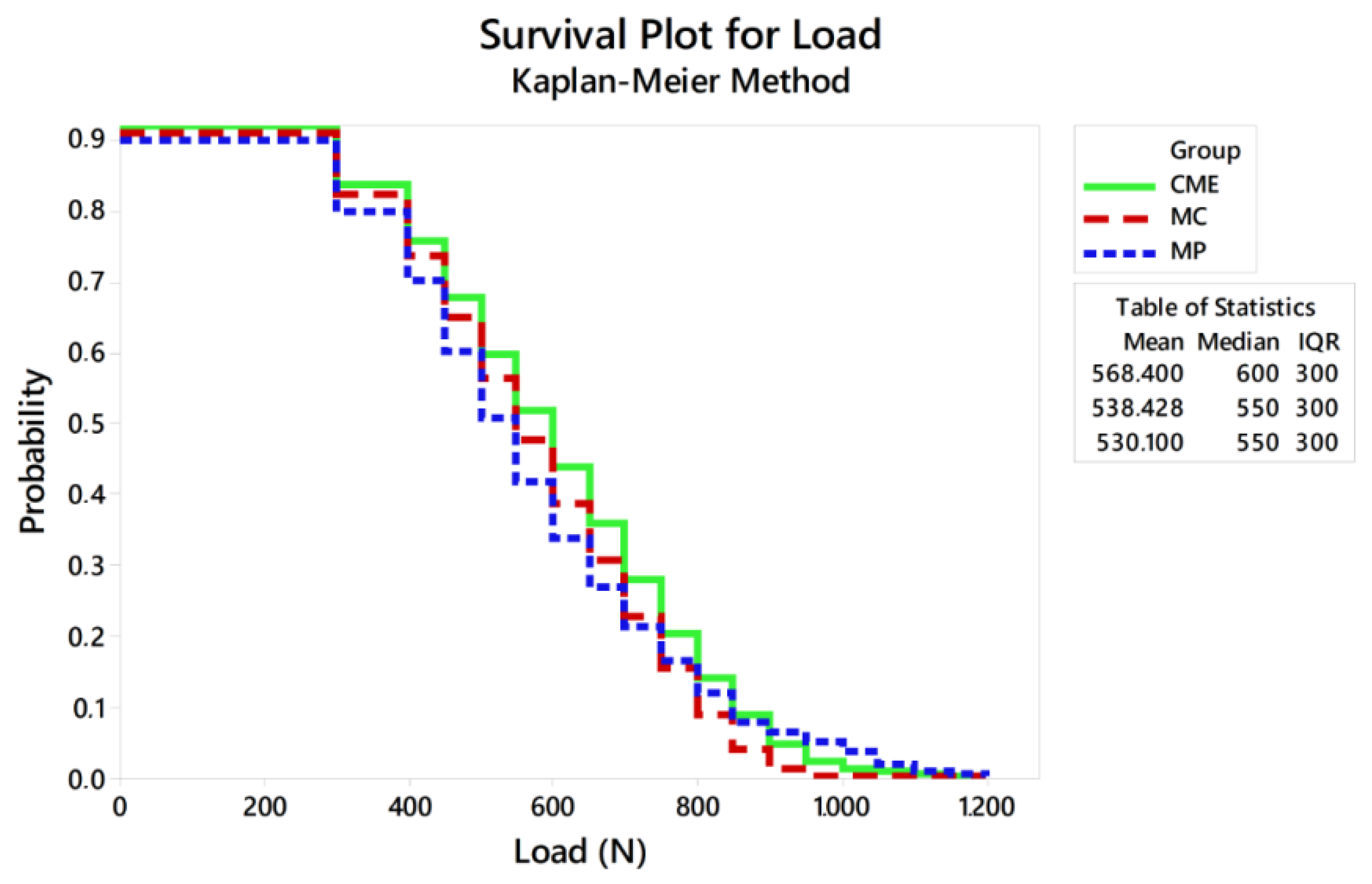
| Survival Probability (%) | MP | MC | CME | |
|---|---|---|---|---|
| 300 N | Upper bound | 88 | 87 | 85 |
| Average | 84 A | 82 A | 80 A | |
| Lower bound | 79 | 77 | 74 | |
| 600 N | Upper bound | 50 | 36 | 40 |
| Average | 44 A | 30 B | 33 AB | |
| Lower bound | 37 | 24 | 27 | |
| 900 N | Upper bound | 7 | 6 | 9 |
| Average | 5 A | 1 A | 6 A | |
| Lower bound | 2 | 0.5 | 3 | |
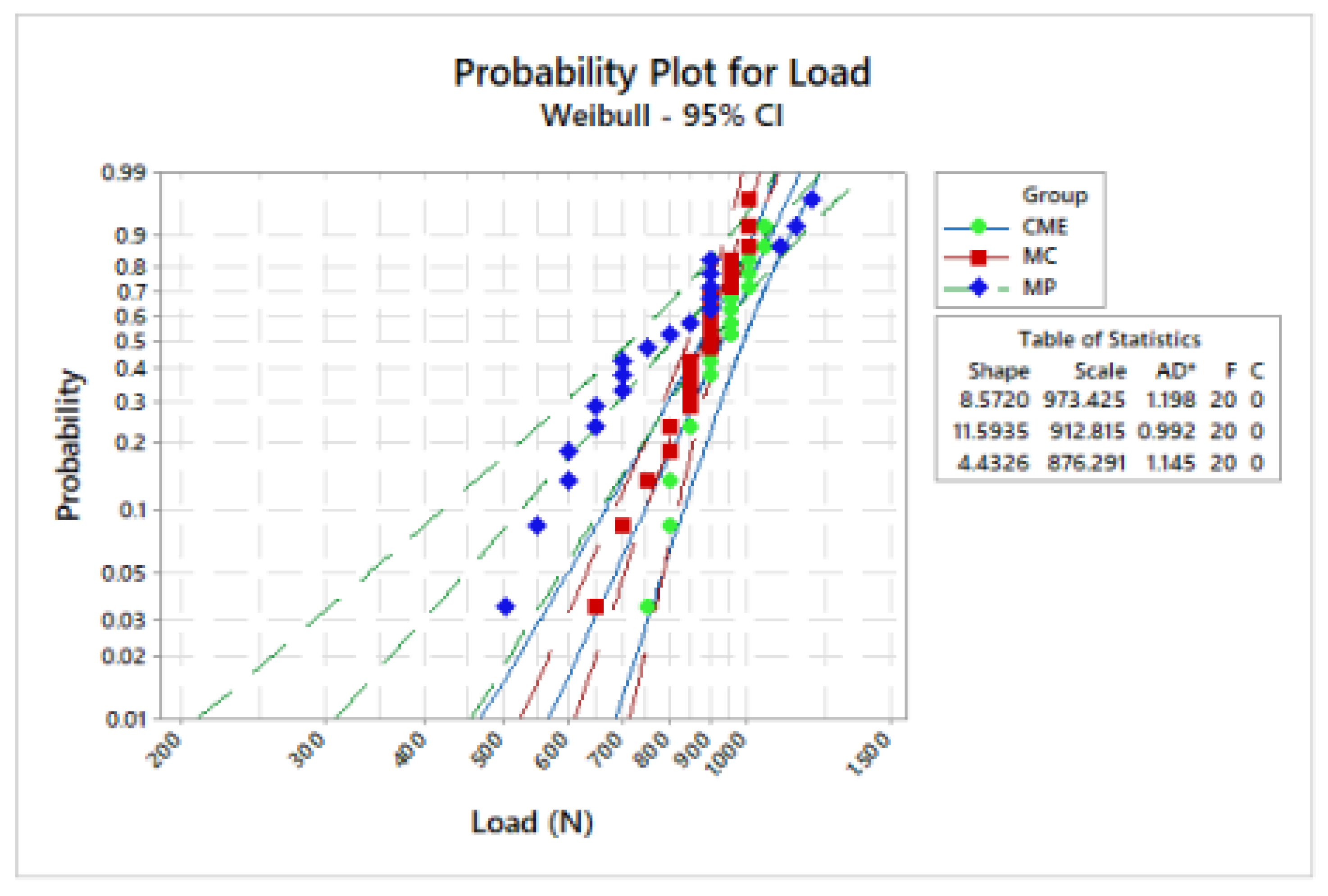
| Groups | m (CI) | σ (CI) |
|---|---|---|
| MP | 8.5 (6.2–1.6) | 973.4 (921.9–1027.7) |
| CME | 4.4 (3.2–6.1) | 912.8 (877.2–949.8) |
| MC | 11.6 (8.1–16.4) | 876.3 (789.1–973.1) |
© 2020 by the authors. Licensee MDPI, Basel, Switzerland. This article is an open access article distributed under the terms and conditions of the Creative Commons Attribution (CC BY) license (http://creativecommons.org/licenses/by/4.0/).
Share and Cite
Tribst, J.P.M.; Dal Piva, A.M.O.; Borges, A.L.S.; Anami, L.C.; Kleverlaan, C.J.; Bottino, M.A. Survival Probability, Weibull Characteristics, Stress Distribution, and Fractographic Analysis of Polymer-Infiltrated Ceramic Network Restorations Cemented on a Chairside Titanium Base: An In Vitro and In Silico Study. Materials 2020, 13, 1879. https://doi.org/10.3390/ma13081879
Tribst JPM, Dal Piva AMO, Borges ALS, Anami LC, Kleverlaan CJ, Bottino MA. Survival Probability, Weibull Characteristics, Stress Distribution, and Fractographic Analysis of Polymer-Infiltrated Ceramic Network Restorations Cemented on a Chairside Titanium Base: An In Vitro and In Silico Study. Materials. 2020; 13(8):1879. https://doi.org/10.3390/ma13081879
Chicago/Turabian StyleTribst, João P. M., Amanda M. O. Dal Piva, Alexandre L. S. Borges, Lilian C. Anami, Cornelis J. Kleverlaan, and Marco A. Bottino. 2020. "Survival Probability, Weibull Characteristics, Stress Distribution, and Fractographic Analysis of Polymer-Infiltrated Ceramic Network Restorations Cemented on a Chairside Titanium Base: An In Vitro and In Silico Study" Materials 13, no. 8: 1879. https://doi.org/10.3390/ma13081879
APA StyleTribst, J. P. M., Dal Piva, A. M. O., Borges, A. L. S., Anami, L. C., Kleverlaan, C. J., & Bottino, M. A. (2020). Survival Probability, Weibull Characteristics, Stress Distribution, and Fractographic Analysis of Polymer-Infiltrated Ceramic Network Restorations Cemented on a Chairside Titanium Base: An In Vitro and In Silico Study. Materials, 13(8), 1879. https://doi.org/10.3390/ma13081879