On the Machinability of an Al-63%SiC Metal Matrix Composite

 ,
,  , ,
, ,  and
and 
Abstract
1. Introduction
2. Machining of Metal Matrix Composites
3. Experimental Procedure
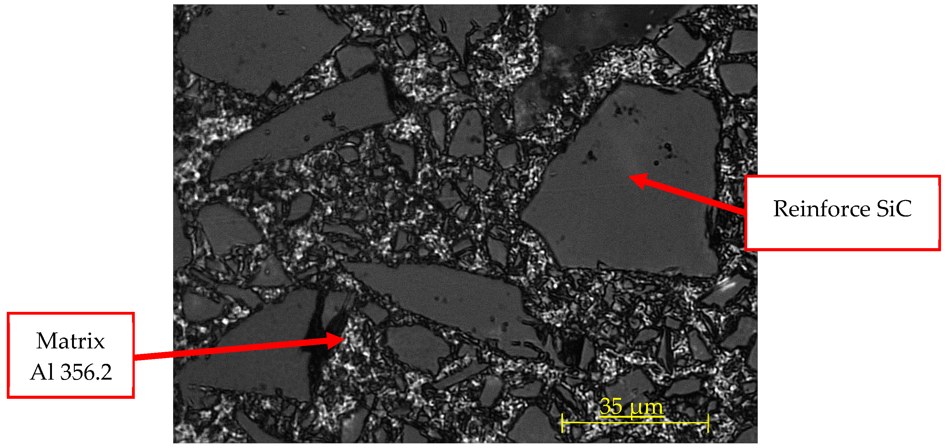
3.1. Material Characterization
3.2. Machining Process
4. Results
4.1. Introduction
4.2. Machining Process
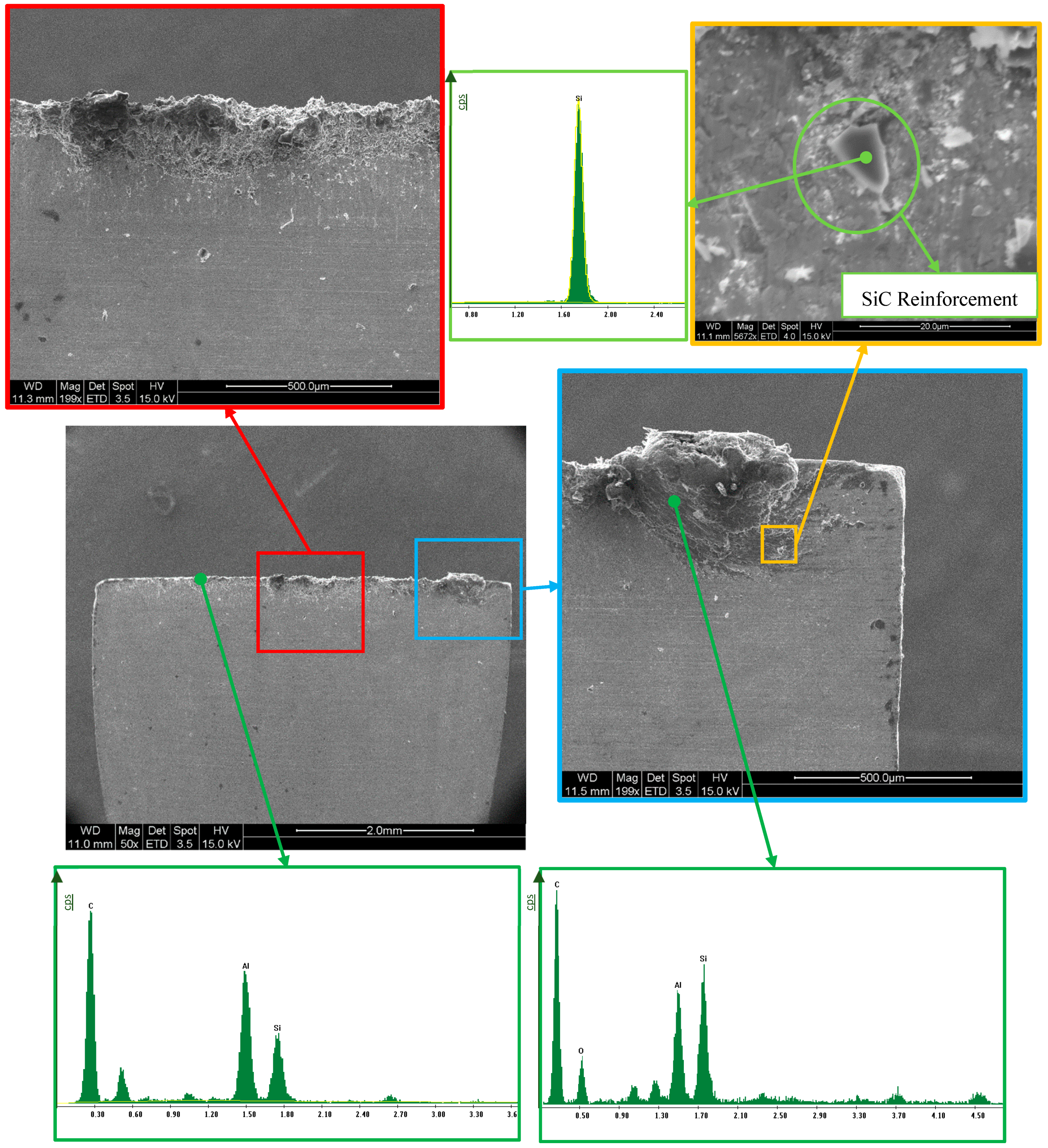
4.3. Chips Characterization
4.4. Tools Characterization
4.5. Cutting Forces
- -
- Microhardness has been studied here. The results show a wide range of values. The highest value belongs to the reinforcement material, whereas the lowest value belongs to the Al matrix. Intermediate values were obtained from matrix or interface areas with matrix reinforcement.
- -
- Sawtooth chips were formed during machining. Some alloys employed in aeronautics, such as the titanium alloy Ti6Al4V or the nickel alloy known as Inconel 718, produce a similar behavior to that observed here, in terms of the chip formation mechanism and the type of chip resulting from the machining.
- -
- Cyclic variation of the shear angle along the machining process can be noticed. Attending to the ISO 3685:1993 standard, the chips formed during the cutting process are of the 6.2 type. The addition of SiC particle reinforcement into the aluminium matrix caused a reduction in its ductility and makes the material ideal for producing semicontinuous chips.
- -
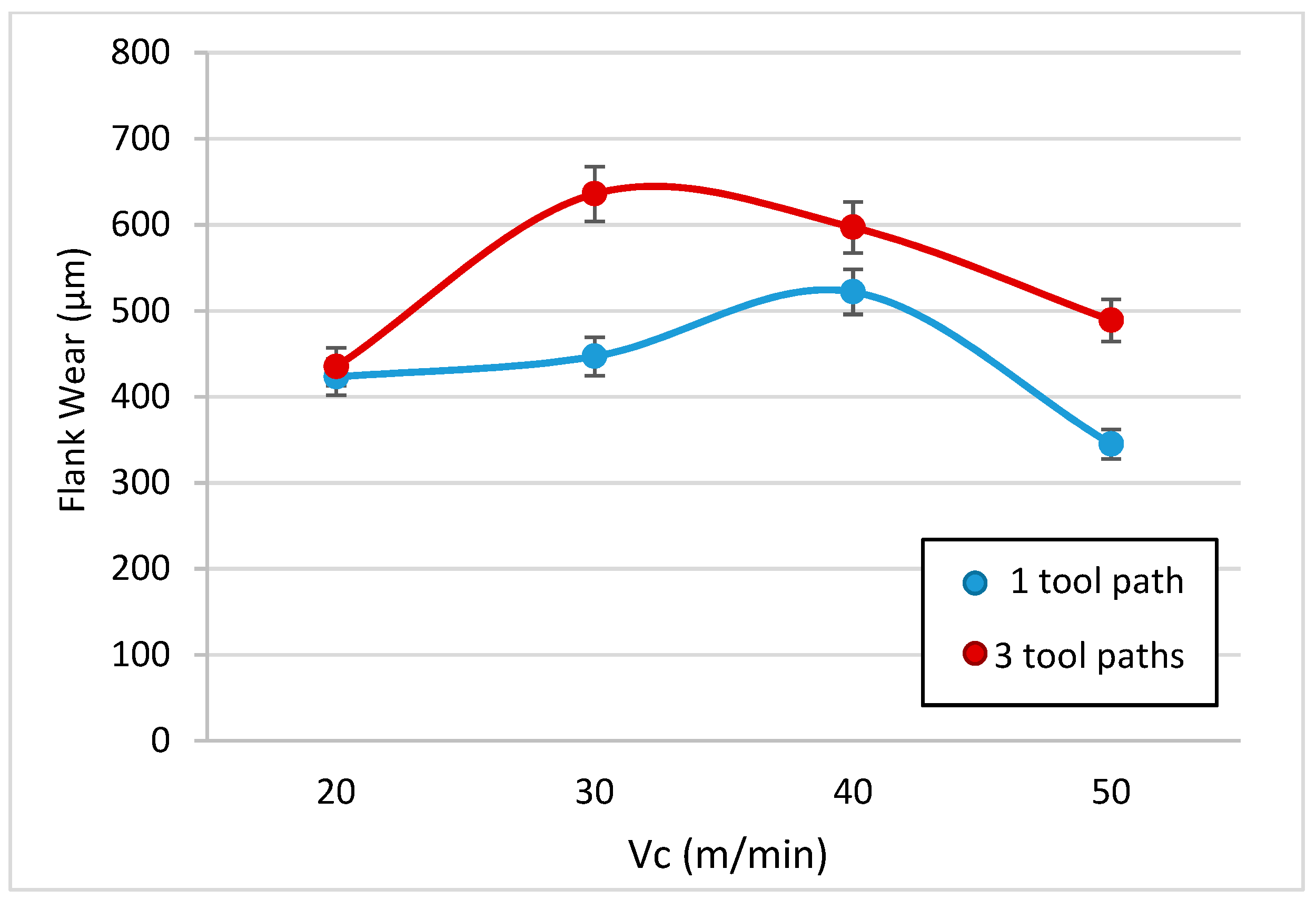
- Tool wear is significant in all cases. Here, secondary adhesion appears (characteristic of Al alloys). The main factor of abrasion wear is the SiC reinforcement, which induces flank wear. A clear relationship with the cutting parameters has not been revealed. The Shaffer model could not be applied to these materials, as the values obtained differ by more than 80% of the calculated value.
- -
- It is possible to appreciate a regrown edge in all tools, where a bigger size is found for those tools produced at higher cutting speeds. Furthermore, it is possible to observe the effect of material loss in the tool, as well as flank wear. This damage is increased with the cutting speed and the time spent machining, and it appears even after short machining times.
- -
- The cutting force Fy showed much higher values than expected, where even after three tool paths it was above the value of Fc. Even though the force Fc is relatively similar between the one and three tool path cases, the values of Fc and M are quite different, where M is always greater than Fc.
5. Conclusions
Author Contributions
Funding
Acknowledgments
Conflicts of Interest
References
- Cardarelli, F. Materials Handbook: A Concise Desktop Reference; Springer: Tucson, AZ, USA, 2008. [Google Scholar]
- Parker, S.P. Dictionary of Scientific & Technical Terms, 6th ed.; McGraw-Hill: New York, NY, USA, 2003. [Google Scholar]
- Wenzelburger, M.; Silber, M.; Gadow, R. Manufacturing of light metal matrix composites by combined thermal spray and semisolid forming processes summary of the current state of technology. Key Eng. Mater. 2010, 425, 217–244. [Google Scholar] [CrossRef]
- Clyne, T.W. An introductory overview of MMC systems, types, and developments. Compr. Compos. Mater. 2000, 3, 1–26. [Google Scholar]
- Cambronero, L.E.G.; Sánchez, E.; Ruiz-Roman, J.M.; Ruiz-Prieto, J.M. Mechanical characterization of AA7015 Aluminium alloy reinforced with ceramics. J. Mater. Process. Technol. 2003, 143–144, 378–383. [Google Scholar] [CrossRef]
- Tosun, G.; Muratoglu, M. The drilling of an Al/SiCp metal-matrix composites. Part I: Microstructure. Compos. Sci. Technol. 2004, 64, 299–308. [Google Scholar] [CrossRef]
- BCC Research. Available online: www.https://www.bccresearch.com/ (accessed on 31 December 2018).
- Evans, A.; San Marchi, C.; Mortensen, A. Metal Matrix Composites in Industry. An Introduction and a Survey; Kluwer Academic Pubs: Berlin, Germany, 2003. [Google Scholar]
- Kainer, K. Metal Matrix Composites—Custom-Made Mtls for Automotive and Aerospace Engineering; Wiley-VCH Verlag GmbH & Co.: Weinheim, Germany, 2006. [Google Scholar]
- Mavhungu, S.T.; Akinlabi, E.T.; Onitiri, M.A.; Varachia, F.M. The processing techniques and behaviour of aluminum. In Aluminium Matrix Composites for Industrial Use: Advances and Trends; Procedia Manufacturing: Amsterdam, The Netherlands, 2017; pp. 178–182. [Google Scholar]
- El-Gallab, M.; Sklad, M. Machining of Al-SiC particulate metal-matrix composites Part I Tool performance. J. Mater. Process. Technol. 1998, 83, 151–158. [Google Scholar] [CrossRef]
- Bodunrin, M.O.; Alaneme, K.K.; Chown, L.H. Aluminium matrix hybrid composites: A review of reinforcement philosophies. J. Mater. Res. Technol. 2015, 4, 434–445. [Google Scholar] [CrossRef]
- Srivyas, P.D.; Charoo, M.S. Role of Reinforcements on the Mechanical and Tribological Behavior of Aluminum Metal Matrix Composites: A Review. Mater. Today 2018, 5, 20041–20053. [Google Scholar] [CrossRef]
- Najem, S.H. Machinability of Al-2024 Reinforced with Al2O3 and or B4C; Repository of College of Material Engineering, University of Babylon: Baghdad, Iraq, 2011. [Google Scholar]
- Kishore, D.S.C.; Rao, K.P.; Mahamani, A. Investigation of cutting force, surface roughness and flank wear in turning of In-situ Al6061-TiC metal matrix composite. Procedia Mater. Sci. 2014, 6, 1040–1050. [Google Scholar] [CrossRef][Green Version]
- Cronjäger, L.; Meister, D. Machining of fibre and particle-reinforced aluminium. Cirp Ann. 1992, 41, 63–66. [Google Scholar] [CrossRef]
- Muthukrishnan, N.; Murugan, M.; Rao, K.P. Machinability issues in turning of Al-SiC (10p) metal matrix composites. Int. J. Adv. Manuf. Technol. 2008, 39, 211–218. [Google Scholar] [CrossRef]
- Tosun, G.; Muratoglu, M. The drilling of AlSiCp metal–matrix composites. Part II: Workpiece surface integrity. Compos. Sci. Technol. 2004, 64, 1413–1418. [Google Scholar] [CrossRef]
- El-Gallab, M.; Sklad, M. Machining of Al-SiC particulate metal matrix composites. Part II: Workpiece surface integrity. J. Mater. Process. Technol. 1998, 83, 277–285. [Google Scholar] [CrossRef]
- Davim, J.P.; Antonio, C.C. Optimisation of cutting conditions in machining of aluminium matrix composites using a numerical and experimental model. J. Mater. Process. Technol. 2001, 112, 78–82. [Google Scholar] [CrossRef]
- Davim, J.P. Design of optimisation of cutting parameters for turning metal matrix composites based on the orthogonal arrays. J. Mater. Process. Technol. 2003, 132, 340–344. [Google Scholar] [CrossRef]
- Ramulu, M.; Rao, P.N.; Kao, H. Drilling of (Al2O3) p6061 metal matrix composites. J. Mater. Process. Technol. 2002, 124, 244–254. [Google Scholar] [CrossRef]
- Kannan, S.; Kishawy, H.A.; Deiab, I. Cutting forces and TEM analysis of the generated surface during machining metal matrix composites. J. Mater. Process. Technol. 2009, 209, 2260–2269. [Google Scholar] [CrossRef]
- El-Kady, O.; Fathy, A. Effect of SiC particle size on the physical and mechanical properties of extruded Al matrix nanocomposites. Mater. Des. 2014, 54, 348–353. [Google Scholar] [CrossRef]
- Wang, T.; Xie, L.J.; Wang, X.B.; Jiao, L.; Shen, J.W.; Xu, H.; Nie, F.M. Surface integrity of high speed milling of AlSiC65p aluminum matrix composites. Procedia CIRP 2013, 8, 475–480. [Google Scholar] [CrossRef]
- Kannan, S.; Kishawy, H.A. Tribological aspects of machining aluminium metal matrix composites. J. Mater. Process. Technol. 2008, 198, 399–406. [Google Scholar] [CrossRef]
- Quigley, O.; Monaghan, J.; O’Reilly, P. Factors affecting the machinability of an AlSiC metal-matrix composite. J. Mater. Process. Technol. 1994, 43, 21–36. [Google Scholar] [CrossRef]
- Monaghan, J.M. The use of a quick-stop test to study the chip formation of an Si:Al metal matrix composite material and its matrix alloy. J. Process. Adv. Mater. 1994, 4, 170–179. [Google Scholar]
- Manna, A.; Bhattacharayya, B. A study on machinability of AlSiC-MMC. J. Mater. Process. Technol. 2003, 140, 711–716. [Google Scholar] [CrossRef]
- Davim, J.P.; Silva, J.; Baptista, A.M. Experimental cutting model of metal matrix composites (MMCs). J. Mater. Process. Technol. 2007, 183, 358–362. [Google Scholar] [CrossRef]
- Dabade, U.A.; Joshi, S.S. Analysis of Chip Formation Mechanism in Machining of AlSicp Metal Matrix Composites. J. Mater. Process. Technol. 2009, 209, 4704–4710. [Google Scholar] [CrossRef]
- Coelho, R.T.; Yamada, S.; Le Roux, T.; Aspinwall, D.K.; Wise, M.L.H. Conventional machining of an Aluminium based SiC Reinforced Metal Matrix Composite (MMC) alloy. In Proceedings of the 13th International Matador Conference, Manchester, UK, 31 March–1 April 1993; p. 125. [Google Scholar]
- Chaudhary, G.; Kumar, M.; Verma, S.; Srivastav, A. Optimization of drilling parameters of hybrid metal matrix composites using response surface methodology. Procedia Mater. Sci. 2014, 6, 229–237. [Google Scholar] [CrossRef][Green Version]
- Vanarotti, M.; Shrishail, P.; Sridhar, B.R.; Venkateswarlu, K.; Kori, S.A. Study of Mechanical Properties & Residual Stresses on Post Wear Samples of A356-SiC Metal Matrix Composites. Procedia Mater. Sci. 2014, 5, 873–882. [Google Scholar]
- Gomez-Parra, A.; Alvarez-Alcon, M.; Salguero, J.; Batista, M.; Marcos, M. Analysis of the evolution of the Built-Up Edge and Built-Up Layer formation mechanisms in the dry turning of aeronautical Aluminium alloys. Wear 2013, 302, 1209–1218. [Google Scholar] [CrossRef]
- Ramnath, B.V.; Elanchezhian, C.; Annamalai, R.M.; Aravind, S.; Atreya, T.S.A.; Vignesh, V.; Subramanian, C. Aluminium Metal Matrix Composites: A Review. Rev. Adv. Mater. Sci. 2014, 38, 55–60. [Google Scholar]
- Basavarajappa, S.; Chandramohan, G.; Davim, J.P.; Prabu, M.; Mukund, K.; Ashwin, M.; Prasannakumar, M. Drilling of hybrid Aluminium matrix composites. Int. J. Adv. Manuf. Technol. 2008, 35, 1244–1250. [Google Scholar] [CrossRef]
- Available online: http://www.matweb.com/search/DataSheet.aspx?MatGUID=f38ba0e663a14183927155e5cc5d21a1&ckck=1 (accessed on 20 December 2019).
- CPS Technologies Corp. Available online: http://www.alsic.com/data-sheets (accessed on 31 December 2018).
- Metallic Materials. Vickers Hardness Test. Part 1: Test Method; AENOR: Madrid, Spain, 2006.
- List, G.; Nouari, M.; Géhin, D.; Gomez, S.; Manaud, J.P.; Le Petitcorps, Y.; Girot, F. Wear behaviour of cemented carbide tools in dry machining of Aluminium alloy. Wear 2005, 259, 1177–1189. [Google Scholar] [CrossRef]
- Gururaja, S.; Ramulu, M.; Pedersen, W. Machining of MMCs: A review. Mach. Sci. Technol. 2013, 17, 41–73. [Google Scholar] [CrossRef]
- Brandes, E.A.; Brook, G.B. Light Metals Handbook; Elsevier Butterworth Heinemann: Oxford, UK, 1998. [Google Scholar]
- Nakayama, K.; Arai, M.; Kanda, T. Machining Characteristics of Hard Materials. Ann. CIRP 1988, 37, 89–92. [Google Scholar] [CrossRef]
- Pedersen, W.; Ramulu, M. Facing SiCp/Mg metal matrix composites with carbide tools. J. Mater. Process. Technol. 2006, 172, 417–423. [Google Scholar] [CrossRef]
- Ozcatalbas, Y. Chip and built-up edge formation in the machining of in situ Al4C3-Al composite. Mater. Des. 2003, 24, 215–221. [Google Scholar] [CrossRef]
- Komanduri, R.; Von Turkovich, B.F. New observations on the mechanism of chip formation when machining titanium alloys. Wear 1981, 69, 179–188. [Google Scholar] [CrossRef]
- Zhang, S.; Li, J.; Zhu, X.; Lv, H. Saw-Tooth chip formation and its effect on cutting force fluctuation in turning of Inconel 718. Int. J. Precis. Eng. Manuf. 2013, 14, 957–963. [Google Scholar] [CrossRef]
- Lin, J.T.; Bhattacharyya, D.; Ferguson, W.G. Chip formation in the machining of SiC-particle-reinforced Aluminium-matrix composites. Compos. Sci. Technol. 1998, 58, 285–291. [Google Scholar] [CrossRef]
- Batista, M. Characterization of Secondary Adhesión Mechanisms and Influence in Tools Wear. Lightweight Alloys Dry Machining Application. Ph.D. Thesis, Cadiz University, Cadiz, Spain, 2013. [Google Scholar]
- Álvarez, M.; Salguero, J.; Sánchez, J.A.; Huerta, M.; Marcos, M. SEM and EDS Characterisation of Layering TiOx Growth onto the Cutting Tool Surface in Hard Drilling Processes of Ti-Al-V Alloys. Adv. Mater. Sci. Eng. 2011. [Google Scholar] [CrossRef]
- Batista, M.; Calamaz, M.; Girot, F.; Salguero, J.; Marcos, M. Using Image Analysis Techniques for Single Evaluation of the Chip Shrinkage Factor in Orthogonal Cutting Process. Key Eng. Mater. 2012, 504–506, 1329–1334. [Google Scholar] [CrossRef]
- Salguero, J.; Batista, M.; Calamaz, M.; Girot, F.; Marcos, M. Cutting Forces Parametric Model for the Dry High Speed Contour Milling of Aerospace Aluminium Alloys. Procedia Eng. 2013, 63, 735–742. [Google Scholar] [CrossRef]


| Alloy | Al | Cu | Fe | Mg | Mn | Si | Ti | Zn | Others |
|---|---|---|---|---|---|---|---|---|---|
| UNS Al356.2 | 91.30–93.20 | 0.10 | 0.12 | 0.30–0.45 | 0.05 | 6.5–7.5 | 0.20 | 0.05 | 0.15 |
| A356.2 | 91.10–93.30 | ≤0.20 | ≤0.20 | 0.25–0.45 | ≤0.10 | 6.5–7.5 | ≤0.20 | ≤0.10 | 0.15 |
| Composition and Properties | AlSiC-9 |
|---|---|
| Matrix: Aluminium alloy A 356.2 | 37 vol % |
| Reinforcement: SiC | 63 vol % |
| Density (g/cm3) | 3.01 |
| Thermal conductivity (W/K∙m) at 298.15 K | 190 |
| Specific heat (J/g∙K) at 298.15 K | 0.741 |
| Young’s modulus (GPa) | 188 |
| Coulomb, shear modulus (GPa) | 76 |
| Cutting Speed (Vc) | 20, 30, 40, 50 m/min |
| Depth of Cut (DoC) | 0.10, 0.20 mm |
| Sample | Force (N) | Time (seconds) | HV (kg/mm2) | Notes |
|---|---|---|---|---|
| 1 | 0.98 | 15 | 1786 | Measured in reinforcement |
| 2 | 1.96 | 15 | 262 | Measured in matrix |
| 3 | 1.96 | 15 | 600 | Measured in interface |
| 4 | 1.96 | 15 | 186 | Measured in matrix |
| Machined Length | 20 m/min | 30 m/min | 40 m/min | 50 m/min | |
|---|---|---|---|---|---|
| Angle wear (°) | one tool path | 7.85 | 7.72 | 13.94 | 5.28 |
| three tool paths | 2.56 | 12.12 | 3.95 | 14.39 | |
| Flank wear (μm) | one tool path | 423.01 | 447.00 | 522.01 | 345.01 |
| three tool paths | 435.00 | 636.00 | 597.01 | 489.00 |
| Vc | Machined Length | Fc (N) | M (N) |
|---|---|---|---|
| 20 m/min | one tool path | 720,000 | 887,010 |
| three tool paths | 832,007 | 1,118,255 | |
| 30 m/min | one tool path | 900,277 | 1,295,552 |
| three tool paths | 879,159 | 1,351,942 | |
| 40 m/min | one tool path | 837,356 | 1,068,034 |
| three tool paths | 859,668 | 1,308,143 | |
| 50 m/min | one tool path | 811,942 | 1,085,266 |
| three tool paths | 931,908 | 1,434,406 |
© 2020 by the authors. Licensee MDPI, Basel, Switzerland. This article is an open access article distributed under the terms and conditions of the Creative Commons Attribution (CC BY) license (http://creativecommons.org/licenses/by/4.0/).
Share and Cite
Repeto, D.; Fernández-Vidal, S.R.; Mayuet, P.F.; Salguero, J.; Batista, M. On the Machinability of an Al-63%SiC Metal Matrix Composite. Materials 2020, 13, 1186. https://doi.org/10.3390/ma13051186
Repeto D, Fernández-Vidal SR, Mayuet PF, Salguero J, Batista M. On the Machinability of an Al-63%SiC Metal Matrix Composite. Materials. 2020; 13(5):1186. https://doi.org/10.3390/ma13051186
Chicago/Turabian StyleRepeto, David, Severo Raul Fernández-Vidal, Pedro F. Mayuet, Jorge Salguero, and Moisés Batista. 2020. "On the Machinability of an Al-63%SiC Metal Matrix Composite" Materials 13, no. 5: 1186. https://doi.org/10.3390/ma13051186
APA StyleRepeto, D., Fernández-Vidal, S. R., Mayuet, P. F., Salguero, J., & Batista, M. (2020). On the Machinability of an Al-63%SiC Metal Matrix Composite. Materials, 13(5), 1186. https://doi.org/10.3390/ma13051186