Article

Methodology for Controlling the Technological Process of Executing Floors Made of Cement-Based Materials

Department of Building Engineering, Wroclaw University of Science and Technology, Wroclaw, Wybrzeże Wyspiańskiego 27, 50-370 Wroclaw, Poland
*
Author to whom correspondence should be addressed.
Materials 2020, 13(4), 948; https://doi.org/10.3390/ma13040948
Submission received: 22 January 2020 / Revised: 13 February 2020 / Accepted: 17 February 2020 / Published: 20 February 2020
(This article belongs to the Special Issue Non-Destructive Testing of Structures)

Abstract

:
The article presents original complex methodology for the effective control of the entire process of executing floors made of cement-based materials. This methodology has been lacking in literature so far. The methodology was developed on the basis of many years of the authors’ experience, which was acquired when diagnosing the technical condition of such floors. The methodology was preceded by a synthetic summary of the most important technological and technical requirements for floors made of cement-based materials. It was also enriched with a discussion of the problem documented by sample research results showing the state that may be the result of disregarding and not performing the necessary control activities.

1. Introduction

Currently, floors are commonly made of cement-based materials. They are used in civil engineering for various purposes, e.g., as the top layer of the floor in residential and industrial buildings, in public buildings, and in multi-car garages [1]. Floors made of cement-based materials can also be a substrate for the finishing layer of other materials, such as epoxy resin coatings, ceramic tiles, parquet, etc. [2,3,4]. The substrate for floors is usually concrete or a reinforced concrete ceiling, but can also often be foamed polystyrene, which is a layer of thermal or sound insulation, which was presented in Figure 1.
In order to make floors made of cement-based materials without faults, it is necessary to comply with the technological and technical requirements that are contained in the standards and set by the designer [5,6,7,8,9,10]. However, this is not the only condition that needs to be met. It is first necessary to ensure by the technical supervision that the conditions necessary to make a decision about the commencement of flooring are met, and then to monitor the entire implementation process on an ongoing basis. In the final phase, strength requirements should be checked before the floor is commissioned. It should be stated that in the case of strength parameters, not only the flexural and compressive strength should be monitored. It should also test the compressive strength along the thickness of the floor. The non-destructive ultrasonic method with the use of exponential heads is irreplaceable for this purpose. Ultrasounds are still very popular in civil engineering (for example for damage detection, as presented in [11]). The problem of lower compressive strength in the upper zone of floors, which is related to the horizontal direction of their concreting, is described, among others, in [12,13]. The subsurface tensile strength and abrasion resistance should also be controlled, which depends on the compressive strength in the upper zone of the floor. This upper zone of the floor is, after all, subjected to direct operational effects, and therefore maintaining an adequate compressive strength and subsurface tensile strength in this particular zone is very important for durability and safety of use [14,15,16,17]. This is very important when the floor is the final finishing layer. If the floor is laid directly on a concrete substrate or a reinforced concrete ceiling, the pull-off adhesion between the floor and the substrate also requires control, which is due to the fact that the durability of the exploited floor is dependent on this parameter [18,19,20].
In order for the entire flooring process to be correct, its control should be effective. Comprehensive control can guarantee this. This control should be complex and methodological. However, such a methodology is missing in the literature. According to the authors, the consequence of this can be seen in the very frequent cases of cement floors being executed badly, regardless of whether they are made of ready-mix cement mortars or prepared directly at the construction site [21,22,23,24]. In construction practice, there are known cases of removing defective floors and then re-executing them again [25,26,27,28,29].
Considering the above, the main goal assumed in this article is to develop—based on many years of experience acquired by the authors when testing the technical condition of floors, the quality of which has been questioned by users—an original and complex methodology for the effective control of the entire process of executing floors made of cement-based materials. The developed methodology is preceded in the article by a list of more important requirements for such floors. These are not only the result of a failure to comply with the relevant requirements, but above all the incorrect control of this technological process, which can be seen to be unmethodical, ineffective and not random. The article has been enriched with a discussion comparing and contrasting the current state and standards of quality control of floor performance with comprehensive control of the developed methodology. Its purpose is to show that the practical application of the proposed methodology will effectively eliminate many implementation problems and thus improve the quality of floors made of cement-based materials.

2. A Synthetic Summary of the Major Requirements for Floors Made of Cement-Based Materials

In the case of floors made of cement-based materials, they can be made of ready-mix cement mortars, or prepared directly at the construction site. Usually, fine aggregate with a grain size of up to 2 mm (e.g., quartz sand) is used to make them. In order to improve their workability, the admixtures in the form of plasticizers are used. The use of plasticizers depends on whether the mixture is laid by hand or by pumping. Table 1 presents a synthetic summary of the major technological and technical requirements for the execution of floors made of cement-based materials. These requirements are the same, regardless of whether the floors are made of ready-mix cement mortars or prepared directly on site.

3. Methodology of Controlling the Technological Process of Executing Floors made of Cement-Based Materials

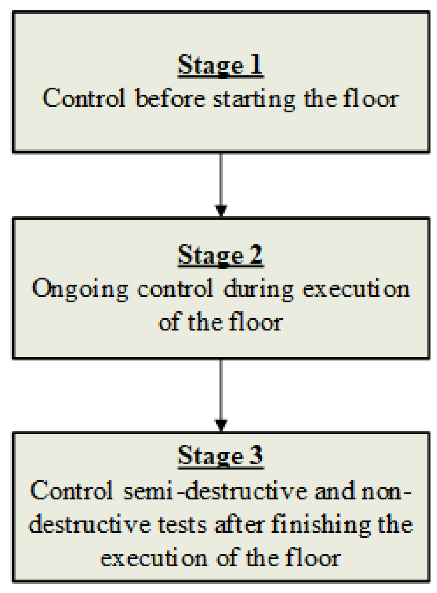
The developed methodology for controlling the technological process of executing floors made of cement-based materials is described below and graphically presented in Figure 2, Figure 3, Figure 4 and Figure 5. Figure 2 presents the general, and Figure 3, Figure 4 and Figure 5 the detailed scheme of this methodology.
In Stage 1, which was presented in Figure 3, the conditions that need to be met must be checked in order to make the decision to start executing the floor.
Stage 1 begins from checking whether the window and door joinery has been built into the building. After ensuring this condition, the relative humidity of the air in the building and the air and substrate temperature on which the floor will be laid are in the required ranges [7]. The next step is to check the evenness of the upper surface of the concrete base. Unevenness of the upper surface of the concrete base is permissible, but the upper and lower deviations need to be maintained according to [30,31,32,33,34,35]. If these conditions are met, insulating foil can be laid on the substrate. The 2nd stage then begins, in which the ongoing process of floor control takes place (Figure 4).
As it can be seen from Figure 4 the first step of Stage 2 is to check the evenness of the insulation foil on the surface of the concrete substrate, reinforced concrete ceiling or foamed polystyrene. In this step, it should be borne in mind that corrugation of the insulation foil laid under the floor is not allowed. The next step is to control the mixing and homogenization of the cement mix according to the mix manufacturer’s requirements. When laying the cement mix, the thickness of the mortar layer and the evenness of the top surface of the floor and its deviation from the horizontal plane should be checked. Peripheral expansion joints are then checked, which should be made of non-absorbent flexible foam, usually with a minimum thickness of 7 mm for the full thickness of the floors. Unevenness of the upper floor surface is only permissible if the upper and lower deviations are maintained, according to [30,31,32,33,34,35]. The next step is to make sure that expansion joints are cut in the first 24 h after executing the floor. Ongoing floor care, consisting of moisturizing it, should then be carried out. Then proceed to the control strength tests after the floor (stage 3).
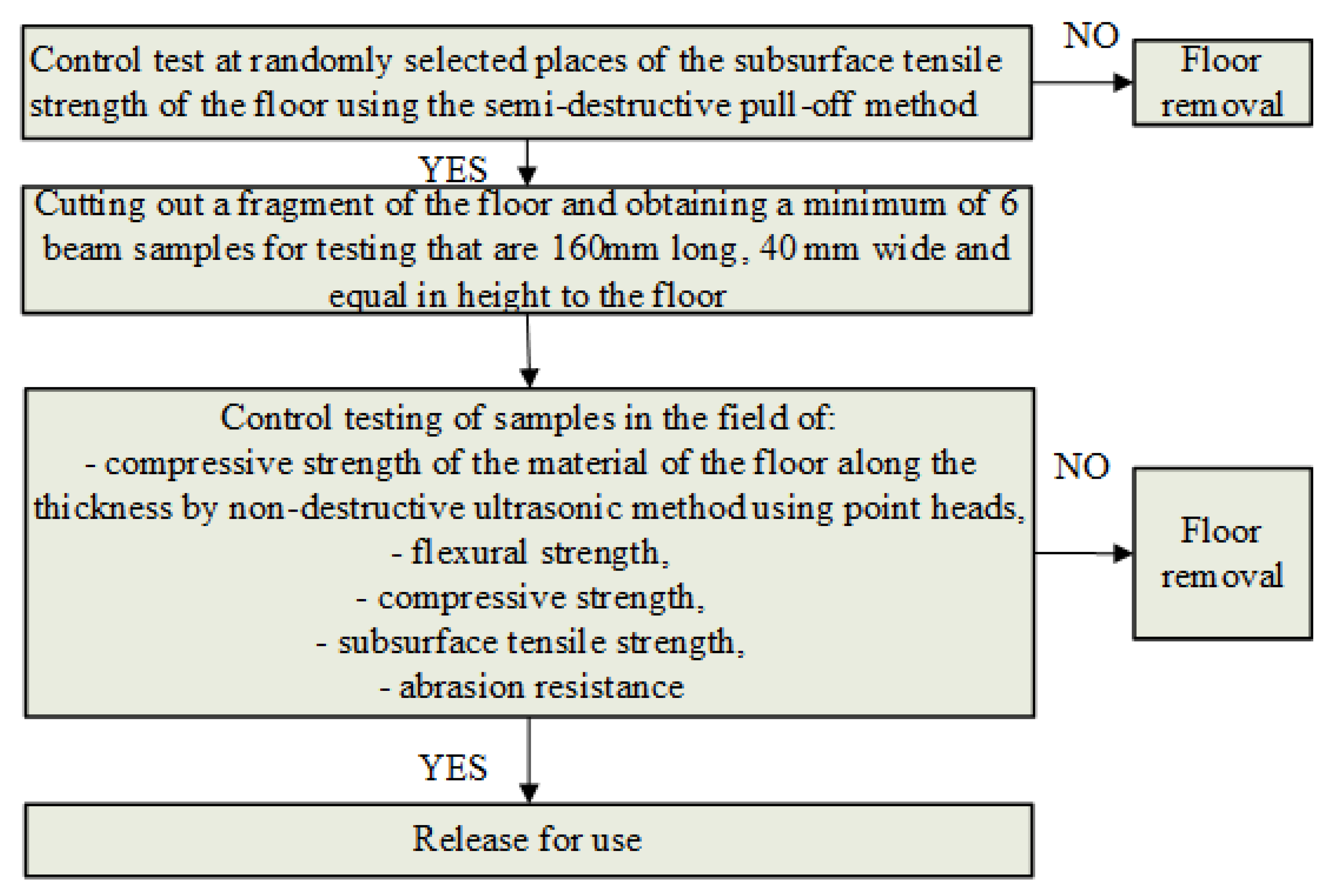
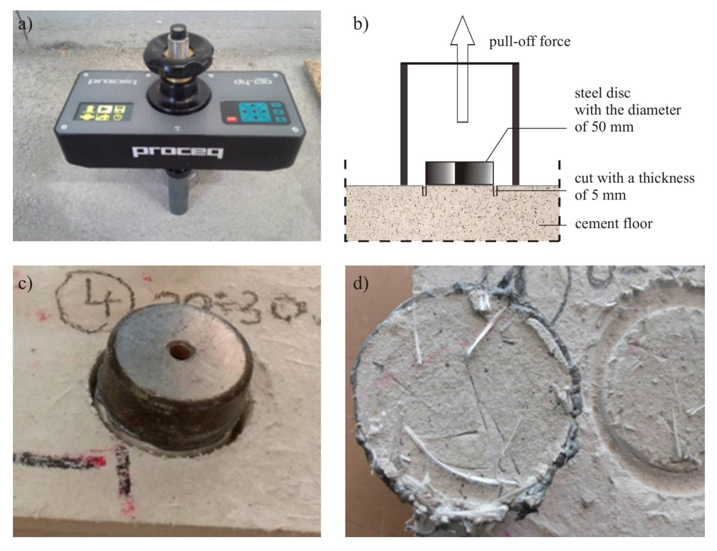
Stage 3 consists of carrying out control strength tests of the floor, without which there should be no final acceptance and commissioning (Figure 5). This stage requires a slightly broader and more detailed explanation. As illustrated in Figure 5, the first step in Stage 3 is to check the subsurface tensile strength of the floor using the semi-destructive pull-off method in randomly made places, 28 days after concreting, and in accordance with EN 1542 [36]. The pull-off tests should begin with selecting representative measuring places and preparing the surface. Then, in these places, an incision should be made in the floor at least 15 mm deep where a steel measuring disc with a diameter of 50 mm is then attached with glue. This disc should then be pulled-off from the floor (Figure 6) and the value of the subsurface tensile strength should be determined in accordance with EN 1542 [36].
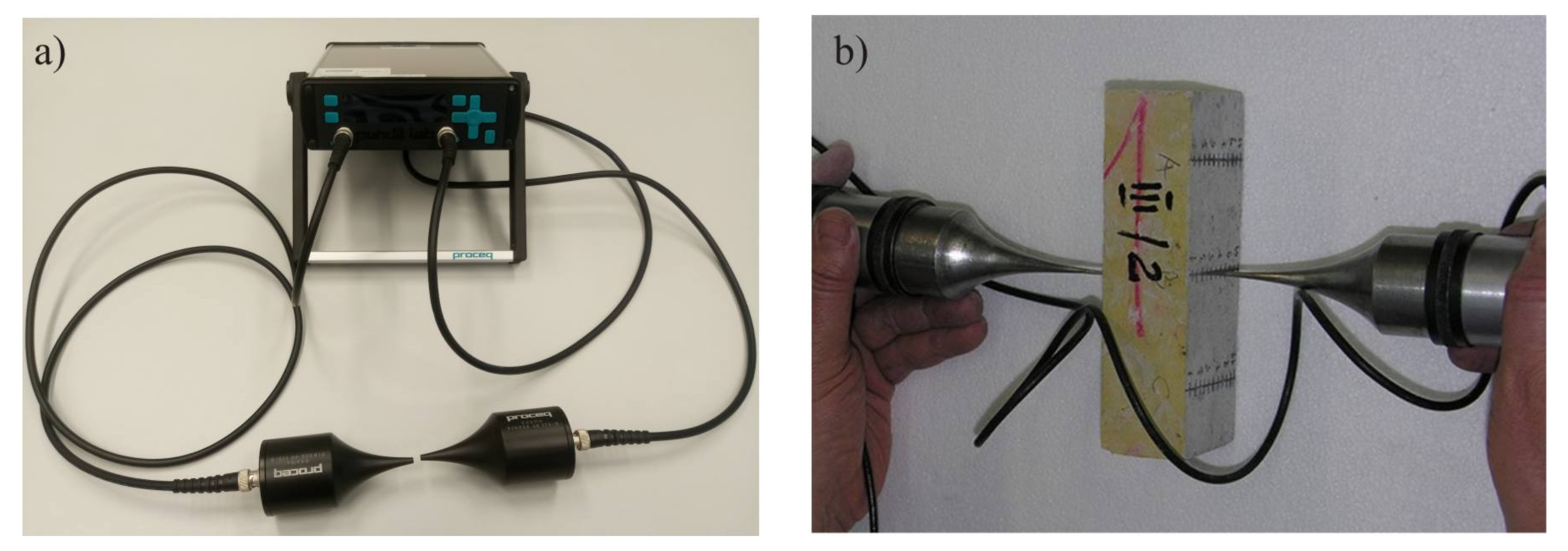
A fragment of the floor, with such a size that at least six beam samples with a length of 160 mm, a width of 40 mm and a height equal to the floor thickness can be obtained, should then be cut off in order to check both the compressive strength of the cement mortar along the thickness and the flexural and compressive strength of the floor. The test samples should first be subjected to ultrasonic testing along the direction of concreting the floor. For ultrasonic testing, it is proposed to use an ultrasonic probe that has special exponential heads with a frequency of 40 kHz and point contact with the tested surface. According to [37] this frequency is optimum for testing cement floor samples with a dimension of 40 × 40 × 160 mm3. The measuring points should be applied to the lateral surfaces of the samples at a spacing of 5 mm in three rows (Figure 7).
After performing the ultrasonic tests, the lower zone of the beam samples should be cut so that their thickness is 40 mm, and then subjected to flexural and compressive strength tests. On the basis of the conducted ultrasonic tests, a correlation relationship (or possibly a hypothetical relationship from the literature) between the velocity of the longitudinal ultrasonic wave and the compressive strength of cement mortar should be developed for the tested floors. This relationship will be used to identify the course of compressive strength along the thickness of the tested floor. The compressive strength in the upper zone should not be less than 10% when compared to the strength in the middle zone. However, the flexural and compressive strength should not be less than the values for the floor that were specified by the designer. After meeting the above strength conditions, the floor can be approved for use. In the event of non-compliance with strength conditions, the floor, after consulting the designer, should be either allowed to be used, or removed.

4. Discussion of the Problem

As already emphasized in the introduction, the literature lacks a comprehensive methodology for controlling the process of making cement floors, which step by step would enforce subsequent control activities. This section only draws attention to those control activities, which, if neglected or omitted, result in serious flooring problems that significantly affect their final quality.
It should be started that the importance of control measures to be taken before flooring process is being started. These activities, included in Stage 1 of the developed methodology, are key to achieving a good final result.
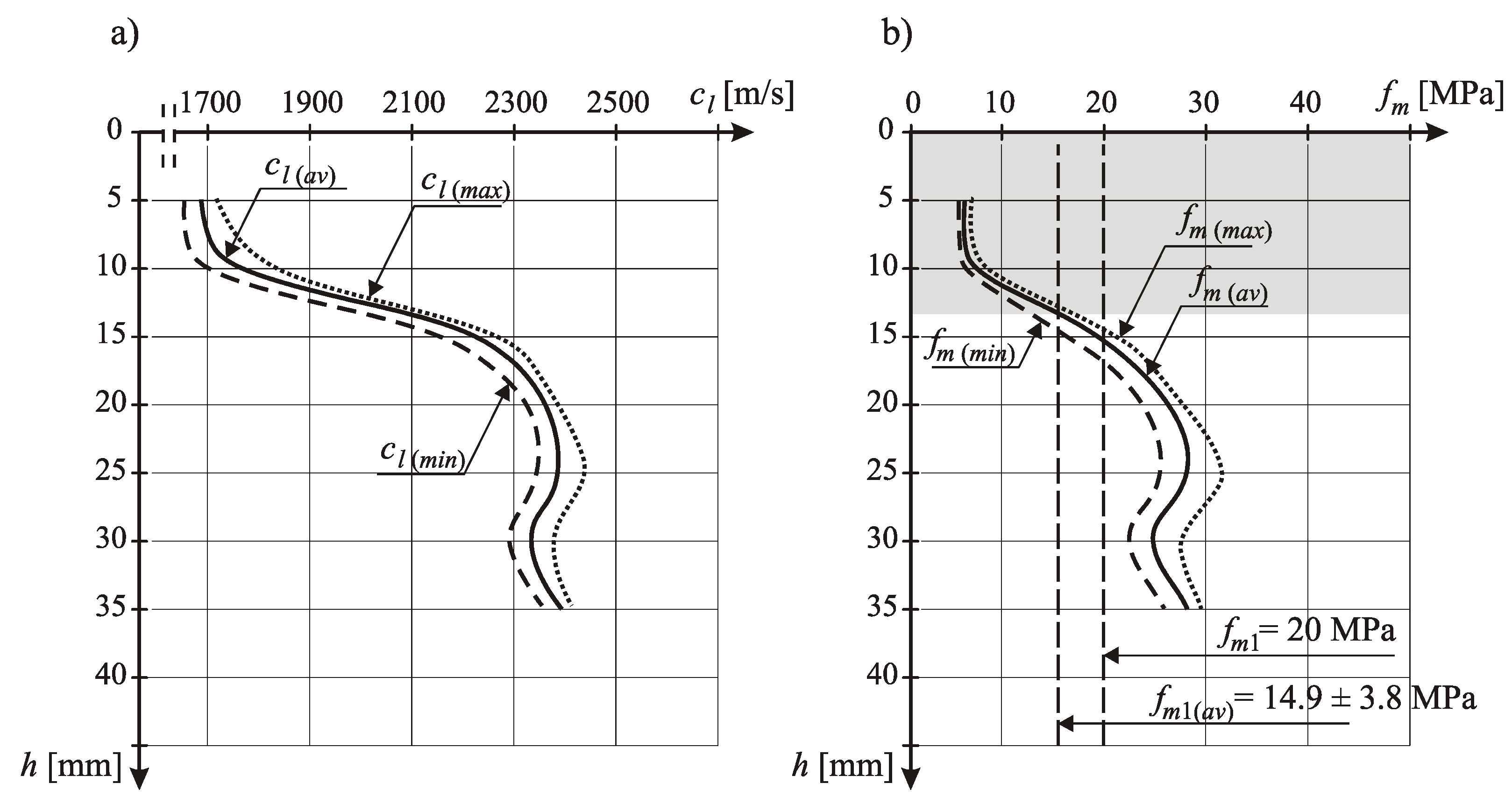
So, currently the important problem is that it is allowed to make floors in buildings without built-in window and door joinery. This promotes the formation of drafts and intense sunlight drying of freshly laid cement mortar [38]. Due consideration is not given to the thermal and humidity conditions that should be provided in the facility, namely the required air and substrate temperature in the range from +10 to +25 °C and relative humidity in the range from 65% to 95%. Cement mortar built into the floor is not cared for by moistening it with water. These are the main reasons for the low surface compressive strength of the upper floor zone and large differences in this strength along the thickness, which is very often demonstrated on the basis of samples taken from the floors tested by the ultrasonic method. An example illustrating the above is Figure 5, which presents examples of the authors’ results of the course of the longitudinal velocity of the ultrasonic wave cl along the thickness h of the cement mortar, and the course of compressive strength fm of the cement mortar along the thickness h of the cement floor determined on this basis. These tests were performed by a non-destructive ultrasonic method with exponential heads with a frequency of 40 kHz.
Figure 8b indicates the mean compressive strength fm1 of 20 MPa, which is required by the designer and declared by the cement mortar manufacturer, and also the average strength fm obtained from the tests and shown with a vertical line. Figure 8 shows that within the subsurface zone of the floor up to a depth of about 15 mm from the upper floor surface, the compressive strength fm was much lower than the strength fm1 required by the designer and declared by the manufacturer, which disqualified this floor. The occurrence of such large differences in strength along the floor thickness could not be seen in aggregate segregation, which is known and described in the literature [39,40,41,42,43,44,45].
An example is also Table 2, which shows how significantly the strength parameters of floors might differ, for which the control activities preceding its execution were neglected in relation to the requirements contained in Table 1.
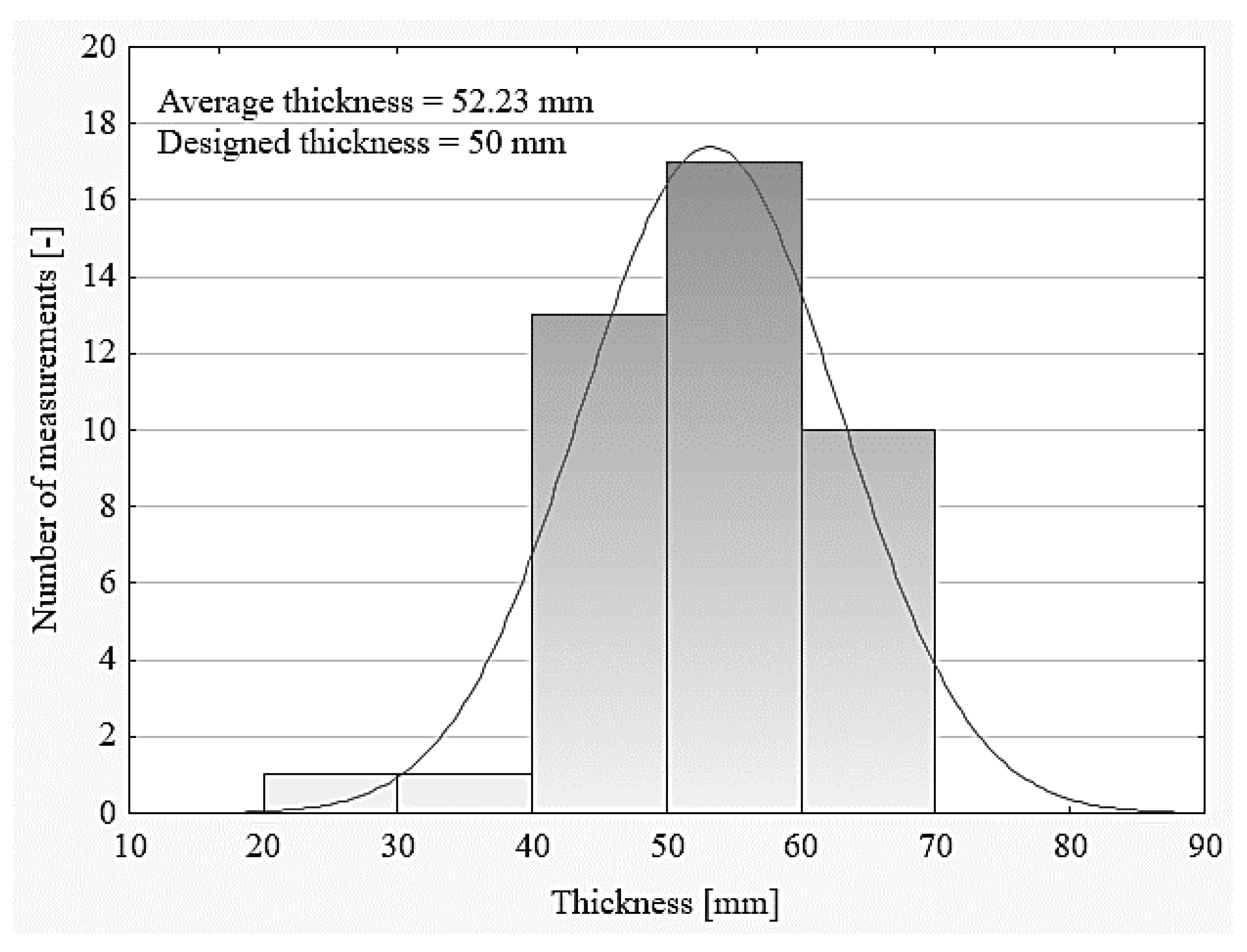
The evenness of the upper surface of the concrete base was not checked, including the occurrence of so-called local “humps”, especially interfering with the leveling of the polystyrene arrangement, which, combined with the lack of ongoing control of the thickness of the mixture being laid, resulted in obtaining a floor thickness that was not in accordance with the design. Numerous studies of the authors show that the thickness of floors is either smaller or larger in relation to the design, which is illustrated in Figure 9. Too low a thickness promotes cracking of the floor during use, whereas too large a thickness limits the floor’s load-bearing capacity.
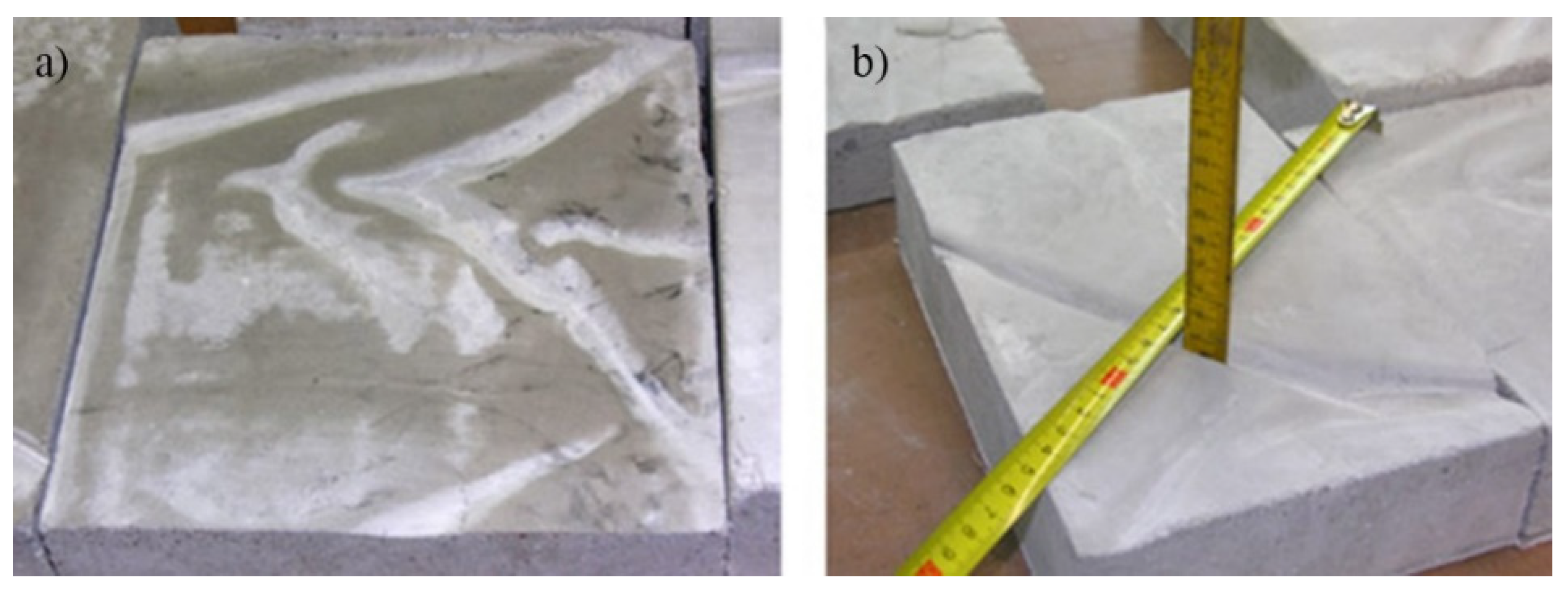
The problem of controlling the evenness of the insulation foil laying on the surface of a concrete substrate or polystyrene was underestimated. As a result of the corrugation of insulation foil laid under the floor on a foamed polystyrene surface, there were irregular grooved recesses on the bottom surface of the floor. As shown in Figure 10, these grooves locally reduced the thickness of the floor by a few, or even several millimeters, which promoted cracking of the floor during use.
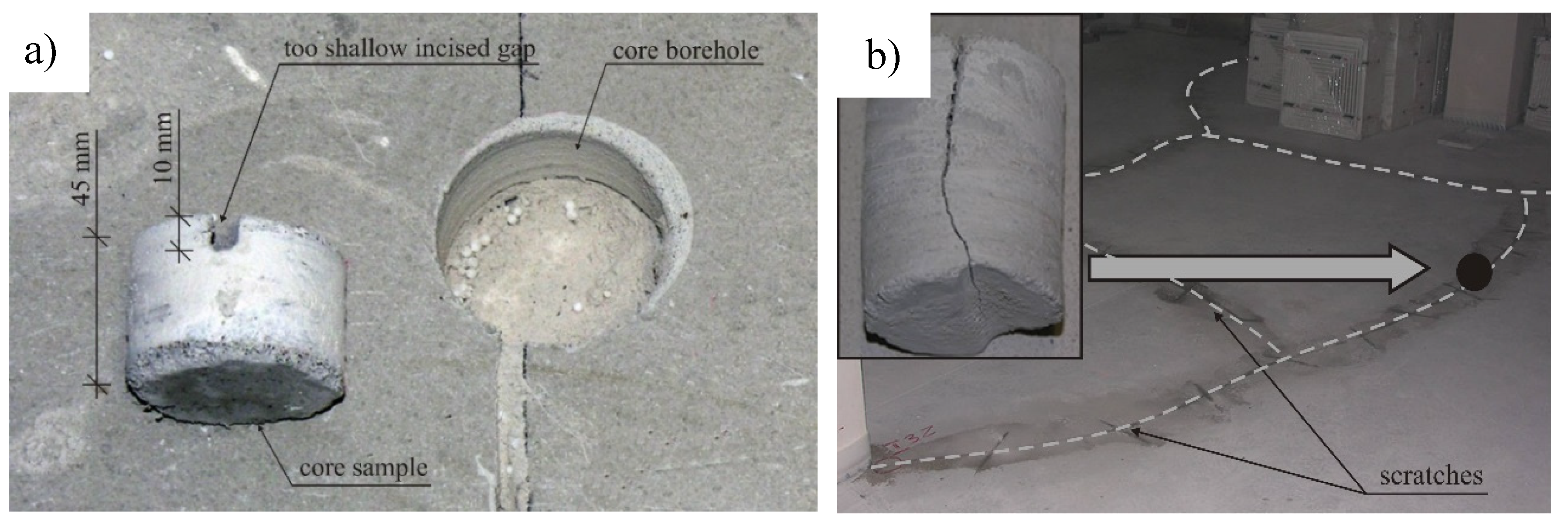
In the developed methodology for controlling the process of making cement floors, in Stage 2, very much attention was paid to checking the expansion joints. Lack of such control, or sporadic controls, contribute to the incorrect execution of expansion joints, or their lack and consequent cracking of floors (for example Figure 11). Incorrect circumferential separating of floors from load-bearing walls results in a lack of continuity of expansion joints, floors being too small in width, joints being too shallow or the filling of joints with a material other than the non-absorbent flexible foam used for this purpose, e.g., multilayer cardboard.
Whereas a common disadvantage are expansion joints that are incorrectly cut, or cut at the wrong time, in cement floors. Such errors cause the dimensions of the dilated fields to be too large, the cuts to be too shallow, or the gaps to be cut too late (Figure 11). The developed methodology clearly indicates the necessary scope of control, which should exclude the problem of incorrectly made expansion joints.
In the methodology developed to control the process of making cement floors, in Stage 3, a lot of attention was paid to control strength tests after flooring. Currently, the compressive and flexural strength is being tested. At present, subsurface tensile strength, abrasion resistance and compressive strength of a cement mortar along the thickness are very rarely tested. Lack of these tests results in less durability or loosening of the applied overlay.

5. Conclusions

The article presents the original and effective methodology of controlling the technological process of executing floors made of cement-based materials, which there is a lack of in the literature. This methodology was developed for the entire process of the cement floor technology, which is also missing in the literature. The methodology also indicated the need to use necessary semi-destructive and non-destructive methods for such control.
The methodology was developed on the basis of many years of experience of the authors, which was acquired during the examination of the technical condition of floors in various construction objects. This methodology has three control stages. Both the individual stages and the methodology as a whole indicate or even force, step by step, consecutive control activities to be carried out during flooring. In the discussion of the problem, attention was drawn to those selected control activities, which are currently being neglected and which result in serious implementation problems. This was documented by sample research results, clearly showing the negative effects of such omissions on the quality of the floors made.
The use in construction practice of the proposed comprehensive methodology for controlling the process of flooring made of cement-based materials should have a positive effect on the current state. It should contribute to the effective elimination of many serious implementation problems and, as a consequence, significantly improve the quality and durability of floors.

Author Contributions

Conceptualization, Ł.S. and J.H.; methodology L.S., J.H.; validation, L.S. and A.H.; writing—original draft preparation, Ł.S. and A.H.; writing—review and editing, J.H.; visualization, Ł.S. and A.H.; supervision, J.H. All authors have read and agreed to the published version of the manuscript.

Funding

This research received funding from the subsidy no. 82010003902 intended for the Departament of Building Engineering at Wrocław University of Science and Technology and funded by the Ministry of Science and Higher Education of Poland (MNiSW).

Conflicts of Interest

The authors declare no conflict of interest.

References

  1. Williamson, N.I.H. Concrete floors for warehousing and distribution facilities: Fit for purpose? Proc. Inst. Civ. Eng. Struct. Build. 1996, 116, 235–243. [Google Scholar] [CrossRef]
  2. Tarr, S.M.; Farny, J.A. Concrete Floors on Ground; Portland Cement Association: Skokie, IL, USA, 2008. [Google Scholar]
  3. Marais, L.R.; Perrie, B.D. Concrete Industrial Floors on the Ground; Portland Cement Institute: Skokie, IL, USA, 1993. [Google Scholar]
  4. Pye, P.; Harrison, H.W. Floors & Flooring: Performance, Diagnosis, Maintenance, Repair and the Avoidance of Defects; BRE Building Elements Series: London, UK, 1997. [Google Scholar]
  5. Deshpande, H.; Joshi, R.; Bangar, P. Design Considerations for Reinforced Concrete Flat Slab Floor System. Int. J. Sci. Eng. Res. 2014, 2229, 5518. [Google Scholar]
  6. Ransom, W.H. Building Failures: Diagnosis and Avoidance; Routledge: London, UK, 2002. [Google Scholar]
  7. Hajduk, P. Projektowanie Podłóg Przemysłowych; Wydawnictwo Naukowe PWNL: Warszawa, Poland, 2013. [Google Scholar]
  8. Czarnecki, L.; Emmons, P. Naprawa i Ochrona Konstrukcji Betonowych; Polski Cement: Kraków, Poland, 2007. [Google Scholar]
  9. Bissonnette, B.; Courard, L.; Garbacz, A. Concrete Surface Engineering; CRC Press: Boca Raton, FL, USA, 2015. [Google Scholar]
  10. Garber, G. Design and Construction of Concrete Floors; Elsevier: London, UK, 2006. [Google Scholar]
  11. Rucka, M.; Wilde, K. Experimental Study on Ultrasonic Monitoring of Splitting Failure in Reinforced Concrete. J. Nondestruct. Eval. 2013, 32, 372–383. [Google Scholar] [CrossRef] [Green Version]
  12. Canbaz, M.; Topçu, I.B.; Ateşin, Ö. Effect of admixture ratio and aggregate type on self-leveling screed properties. Constr. Build. Mater. 2016, 116, 321–325. [Google Scholar] [CrossRef]
  13. Stawiski, B. Ultradźwiękowe Badania Betonów i Zapraw Głowicami Punktowymi; Oficyna Wydawnicza Politechniki Wrocławskiej: Wrocław, Poland, 2009. [Google Scholar]
  14. Chaplin, R. Abrasion resistant concrete floors. In Advances in Concrete Slab Technology; Elsevier: Pergamon, Turkey, 1980; pp. 532–543. [Google Scholar]
  15. Szymanowski, J. Evaluation of the Adhesion between Overlays and Substrates in Concrete Floors: Literature Survey, Recent Non-Destructive and Semi-Destructive Testing Methods, and Research Gaps. Buildings 2019, 9, 203. [Google Scholar] [CrossRef] [Green Version]
  16. Cattell, D. Specialist Floor Finishes: Design and Installation; Routledge: London, UK, 2003. [Google Scholar]
  17. Collepardi, M.; Troli, R.; Bressan, M.; Liberatore, F.; Sforza, G. Crack-free concrete for outside industrial floors in the absence of wet curing and contraction joints. Cem. Concr. Compos. 2008, 30, 887–891. [Google Scholar] [CrossRef]
  18. Sadowski, Ł. Adhesion in Layered Cement Composites; Springer: Cham, Switzerland, 2019. [Google Scholar]
  19. Sadowski, Ł.; Żak, A.; Hoła, J. Multi-sensor evaluation of the concrete within the interlayer bond with regard to pull-off adhesion. Arch. Civ. Mech. Eng. 2018, 18, 573–582. [Google Scholar] [CrossRef]
  20. Sadowski, Ł.; Hoła, J.; Czarnecki, S.; Wang, D. Pull-off adhesion prediction of variable thick overlay to the substrate. Autom. Constr. 2018, 85, 10–23. [Google Scholar] [CrossRef]
  21. Nowobilski, T.; Hoła, B. Flooring in housing building—An overview of material solutions (in Polish). Builder 2017, 21, 84–87. [Google Scholar]
  22. Hoła, J.; Sadowski, Ł.; Nowacki, A. Analysis of the causes of cracks in marble slabs in a large-surface floor of a representative commercial facility. Eng. Fail. Anal. 2019, 97, 1–9. [Google Scholar] [CrossRef]
  23. Gajzler, M. Supporting of repairs processes of concrete industrial floors. Eng. Struct. Technol. 2016, 8, 8–14. [Google Scholar] [CrossRef] [Green Version]
  24. Bissonnette, B.; Attiogbe, E.K.; Miltenberger, M.; Fortin, C. Drying Shrinkage, Curling and Joint Opening of Slabs on Ground. ACI Mater. J. 2007, 104, 259–266. [Google Scholar]
  25. Hoła, J.; Sadowski, Ł.; Hoła, A. The effect of failure to comply with technological and technical requirements on the condition of newly built cement mortar floors. J. Mater. Des. Appl. 2019, 233, 268–275. [Google Scholar] [CrossRef]
  26. Delatte, N. Using Failure Case Studies in Civil Engineering Education. Forensic Eng. 2000, 430–440. [Google Scholar]
  27. Tang, P.; Huber, D.; Akinci, B. Characterization of Laser Scanners and Algorithms for Detecting Flatness Defects on Concrete Surfaces. J. Comput. Civ. Eng. 2011, 25, 31–42. [Google Scholar] [CrossRef]
  28. Bissonnette, B.; Courard, L.; Beushausen, H.; Fowler, D.; Trevino, M.; Vaysburd, A. Recommendations for the repair, the lining or the strengthening of concrete slabs or pavements with bonded cement-based material overlays. Mater. Struct. 2013, 46, 481–494. [Google Scholar] [CrossRef] [Green Version]
  29. Douglas, J.; McEwen, I. Defects diagnosis—A case study involving chemical analysis. Constr. Build. Mater. 1998, 12, 259–267. [Google Scholar] [CrossRef]
  30. Toleranzen im Hochbau Bauwerke; DIN 18202: Berlin Germany, 2013.
  31. Loprencipe, G.; Cantisani, G. Evaluation methods for improving surface geometry of concrete floors: A case study. Case Stud. Struct. Eng. 2015, 4, 14–25. [Google Scholar] [CrossRef] [Green Version]
  32. Walsh, K.D.; Bashford, H.H.; Mason, B.C.A. State of Practice of Residential Floor Slab Flatness. J. Perform. Constr. Facil. 2001, 15, 127–134. [Google Scholar] [CrossRef]
  33. Face, A. Floor flatness and levelness: The F-number system. Constr. Specif. 1987, 40, 124–132. [Google Scholar]
  34. Posadzki z Betonu i Zaprawy Cementowej. Wymagania i Badania Techniczne przy Odbiorze; PN-62/B-10145: Warszawa, Poland, 1962.
  35. Standard Test Method for Determining FF Floor Flatness and FL Floor Levelness Numbers; ASTM 1155M-96: West Conshohocken, PA, USA, 2001.
  36. Wyroby i Systemy do Ochrony i Napraw Konstrukcji Betonowych-Metody Badań-Pomiar Przyczepności Przez Odrywanie; PN-EN 1542: Warszawa, Poland, 2004.
  37. Gudra, T.; Stawiski, B. Non-destructive strength characterization of concrete using surface waves. Ndt E Int. 2000, 33, 1–6. [Google Scholar] [CrossRef]
  38. Anderberg, A.; Wadsö, L. Drying and Hydration of Cement Based Self-Leveling Flooring Compounds. Dry. Technol. 2007, 25, 1995–2003. [Google Scholar] [CrossRef]
  39. Navarrete, I.; Lopez, M. Understanding the relationship between the segregation of concrete and coarse aggregate density and size. Constr. Build. Mater. 2017, 149, 741–748. [Google Scholar] [CrossRef]
  40. Gao, X.; Zhang, J.; Su, Y. Influence of vibration-induced segregation on mechanical property and chloride ion permeability of concrete with variable rheological performance. Constr. Build. Mater. 2019, 194, 32–41. [Google Scholar] [CrossRef]
  41. Safawi, M.I.; Iwaki, I.; Miura, T. The segregation tendency in the vibration of high fluidity concrete. Cem. Concr. Res. 2004, 34, 219–226. [Google Scholar] [CrossRef]
  42. Navarrete, I.; Lopez, M. Estimating the segregation of concrete based on mixture design and vibratory energy. Constr. Build. Mater. 2016, 122, 384–390. [Google Scholar] [CrossRef]
  43. Josserand, L.; Coussy, O.; De Larrard, F. Bleeding of concrete as an ageing consolidation process. Cem. Concr. Res. 2006, 36, 1603–1608. [Google Scholar] [CrossRef]
  44. Topçu, I.B.; Elgün, V.B. Influence of concrete properties on bleeding and evaporation. Cem. Concr. Res. 2004, 34, 275–281. [Google Scholar] [CrossRef]
  45. Hoshino, M. Relation between bleeding, coarse aggregate, and specimen height of concrete. Mater. J. 1989, 86, 185–190. [Google Scholar]
  46. Metody Badania Materiałów na Podkłady Podłogowe-Część 2: Oznaczanie Wytrzymałości na Zginanie i ściskanie; EN 13892-2: Warszawa, Poland, 2004.
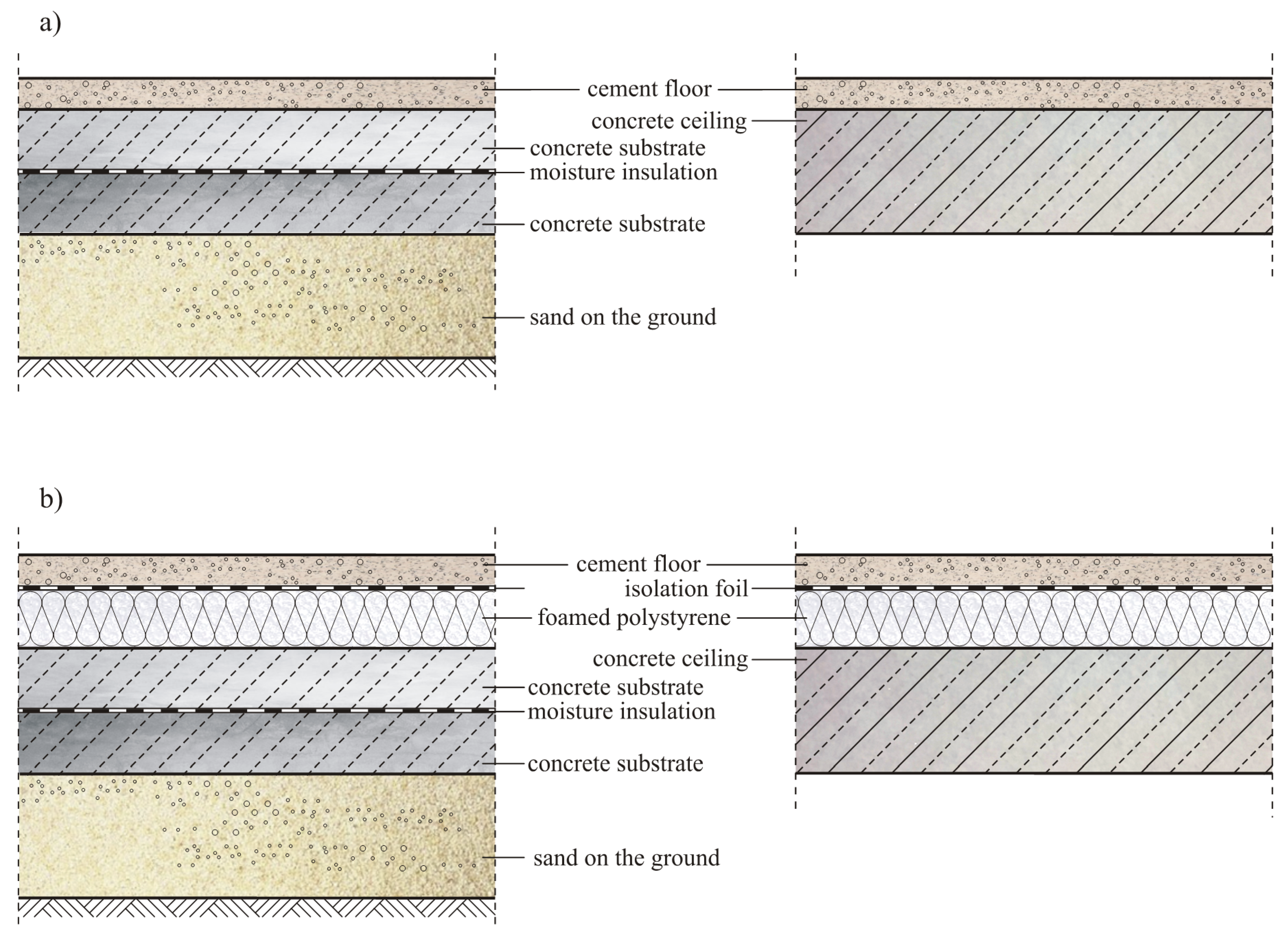
Figure 1. Applied variants of various floor systems made on: (a) a concrete substrate or a reinforced concrete ceiling: (b) a foamed polystyrene laid on a concrete substrate or reinforced concrete ceiling.
Materials 13 00948 g001
Figure 2. General diagram illustrating the developed methodology.
Materials 13 00948 g002
Figure 3. Methodology of controlling the technological process of executing floors made of cement-based materials—Stage 1 (control before starting the floor).
Materials 13 00948 g003
Figure 4. Methodology of controlling the technological process of executing floors made of cement-based materials—Stage 2 (ongoing control during execution of the floor).
Materials 13 00948 g004
Figure 5. Methodology of controlling the technological process of executing floors made of cement-based materials—Stage 3 (control strength tests after finishing the execution of the floor).
Materials 13 00948 g005
Figure 6. Control of the subsurface tensile strength of the floor using the pull-off method: (a) pull-off apparatus; (b) scheme of the method; (c) view of the glued steel disc; (d) view of the floor surface after the pull-off tests.
Materials 13 00948 g006
Figure 7. Example view: (a) head and probe for ultrasonic testing; (b) floor sample tested using the ultrasonic method.
Materials 13 00948 g007
Figure 8. An example of the course: (a) the longitudinal velocity of the ultrasonic wave cl along the thickness h and (b) the compressive strength fm of the cement mortar along thickness h.
Materials 13 00948 g008
Figure 9. The thickness of the floors in comparison with the designed thickness (based on the data presented in [25]).
Materials 13 00948 g009
Figure 10. Example view: (a) the bottom surface of the floor, with grooved recesses constituting the “imprint” of the corrugated foil and (b) measuring the depth of the grooved cavities.
Materials 13 00948 g010
Figure 11. An exemplary view: (a) of a core borehole made in the floor, and also a core sample showing an expansion joint that is cut too shallow and (b) cracks on the surface of floors, along with an approximation of the cut core sample documenting the depth of one of the cracks.
Materials 13 00948 g011
Table 1. A synthetic summary of the major technological and technical requirements for the execution of floors made of cement-based materials.
Important Technological and Technical Requirements
Floor thickness - Compliant with the design, usually 40–60 mm.
Beginning of the execution of the floor
-
After building windows and doors in the building,
-
In the absence of so-called drafts that overdry the cement-based material,
-
Without the possibility of intense sunlight or heating of the cement-based material,
-
At ambient and substrate temperatures between +10 and +25 °C,
-
At a relative humidity of 65%–95%.
Preparation of the mixtureMechanical mixing:
-
without homogenizing the mixture,
-
with homogenizing the mixture according to standards in the mix manufacturer’s requirements.
Unevenness of the surface of a concrete substrate or reinforced concrete ceiling - It is required not to exceed the upper and lower deviations, recorded in [30,31,32,33,34,35].
Corrugation of insulation foil laid under the floor -  It is not allowed.
The deviation of the surface from the horizontal plane - It is required not to exceed the upper and lower deviations, recorded in [30,31,32,33,34,35].
Execution of peripheral expansion joints
-
For full thickness of floors, made of non-absorbent elastic foam,
-
Minimum joint width 7 mm.
Execution of cut expansion joints
-
Maximum field size should be 36 m2,
-
Maximum length of dilated field should be 6 m,
-
The maximum proportions of the sides of the dilated field 1:1.5,
-
The minimum depth of cut expansion joints from 1/3 to 1/2 of the floor thickness, at right angles,
-
Joint widths from 3 to 5 mm.
Deadline for making cut-in expansion joints - In the first 24 h after execution of the floor.
Compressive strength - According to the project; usually at least 20 MPa.
Flexural strength - According to the project; usually at least 5 MPa.
Subsurface tensile strength - According to the project; usually at least 1.5 MPa [15].
Abrasion resistance - According to the project, usually a maximum of 22 cm3
Cracks - They are not allowed [7].
Unevenness of the surface of a floor - It is required not to exceed the upper and lower deviations, recorded in [30,31,32,33,34,35].
Table 2. Sample results of strength tests carried out for one of the cement floors tested in accordance with [46] (own study based on the data provided [25]).
Summary of Average Strength Values
Subsurface tensile strength fh (MPa):
-
Obtained on the basis of research
-
Required according to Table 1
0.55 ± 0.21
1.5
Compressive strength (MPa):
-
Obtained on the basis of research
-
Required according to Table 1
15.1 ± 4.5
20.0
Flexural strength (MPa):
-
Obtained on the basis of research
-
Required according to Table 1
2.3 ± 1.0
5.0