Selective Laser Melting of Patient Individualized Osteosynthesis Plates—Digital to Physical Process Chain


Abstract
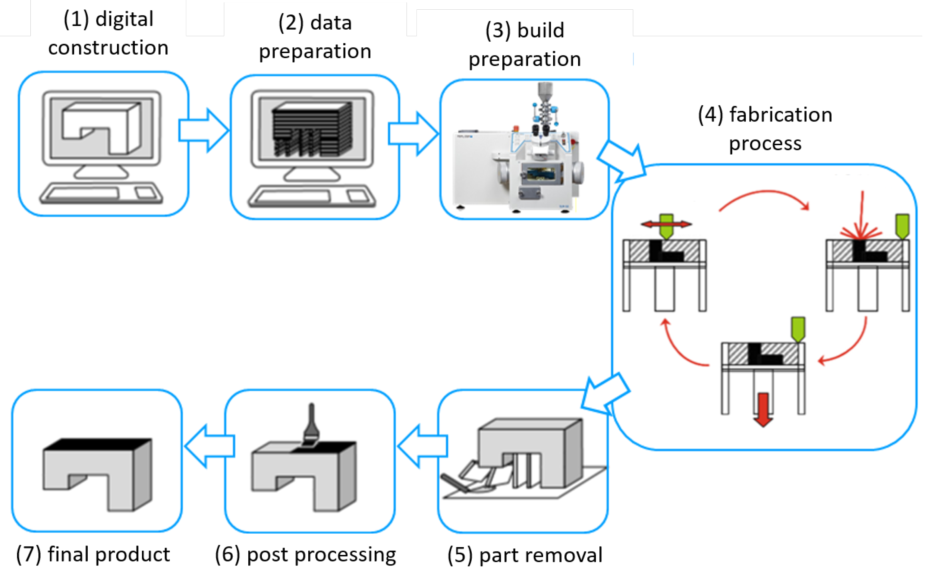
1. Introduction
2. Material and Methods
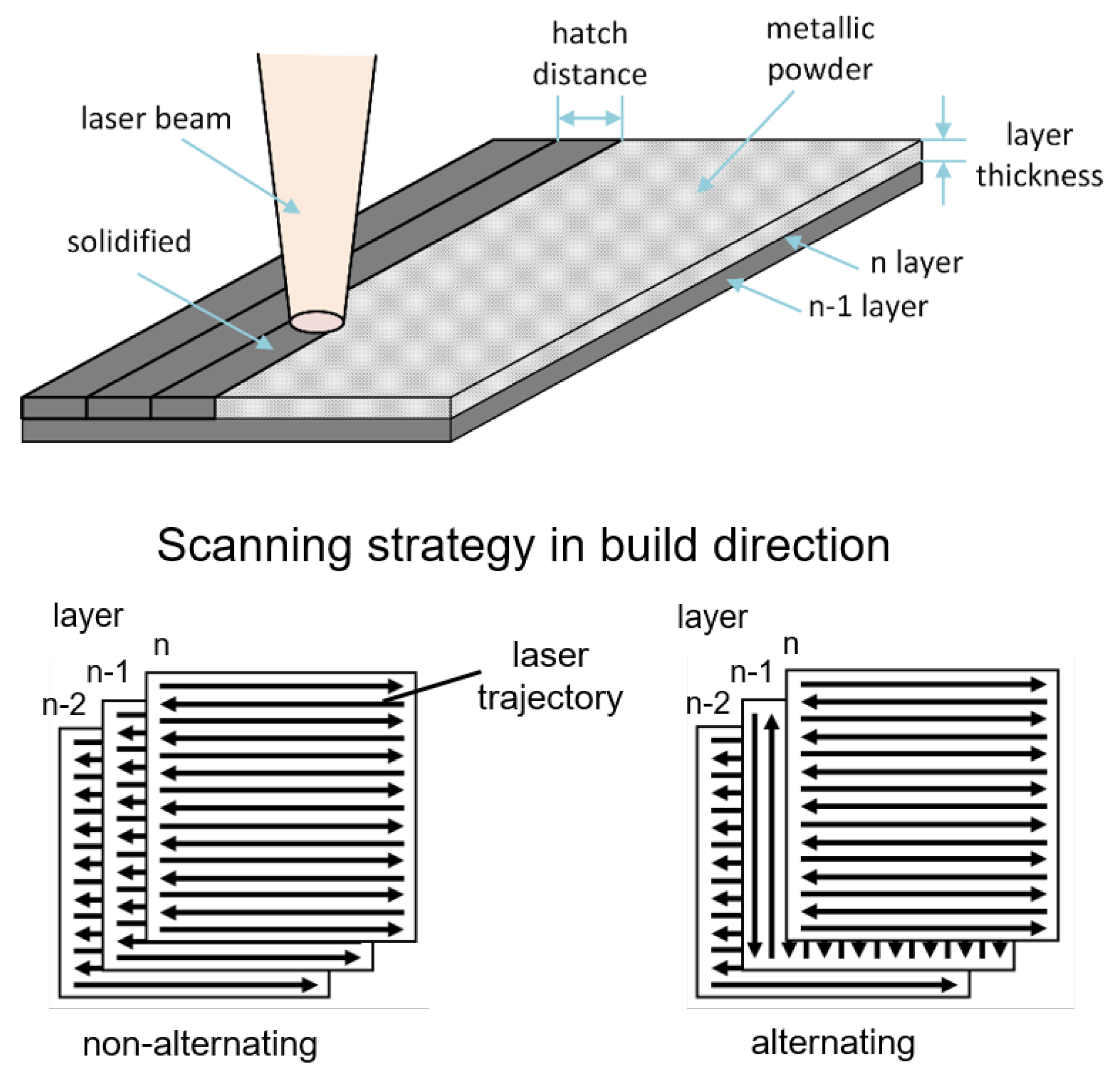
2.1. Selective Laser Melting Conditions
2.2. Powder Characteristics and Mechanical Properties
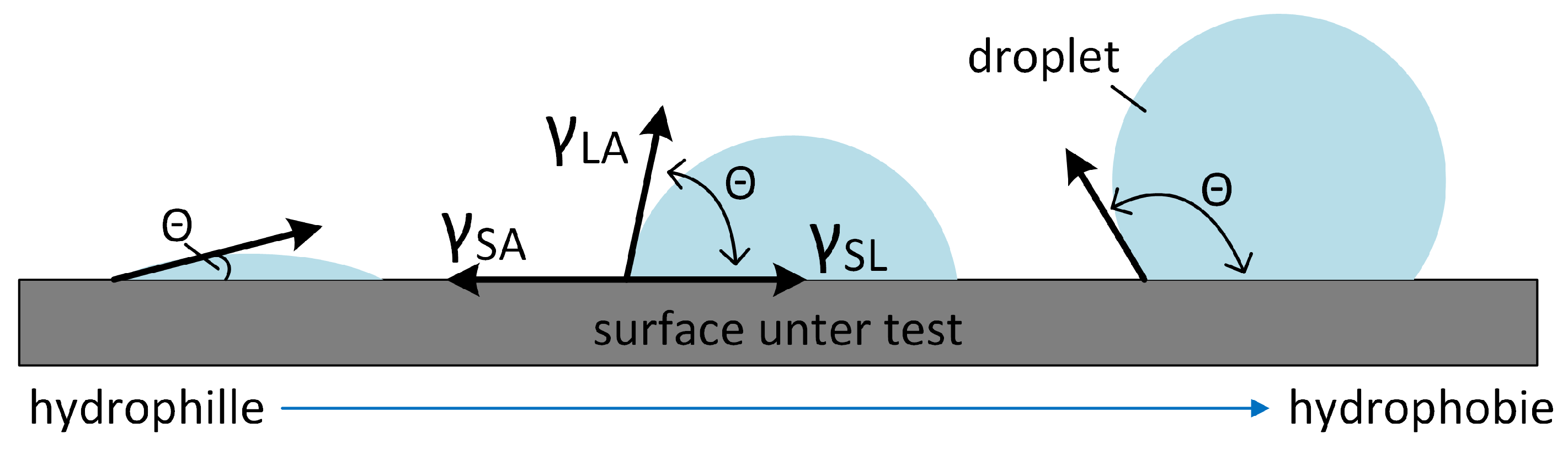
2.3. Wetting Characteristics
2.4. Optical Characterization Tools
3. Results and Discussion
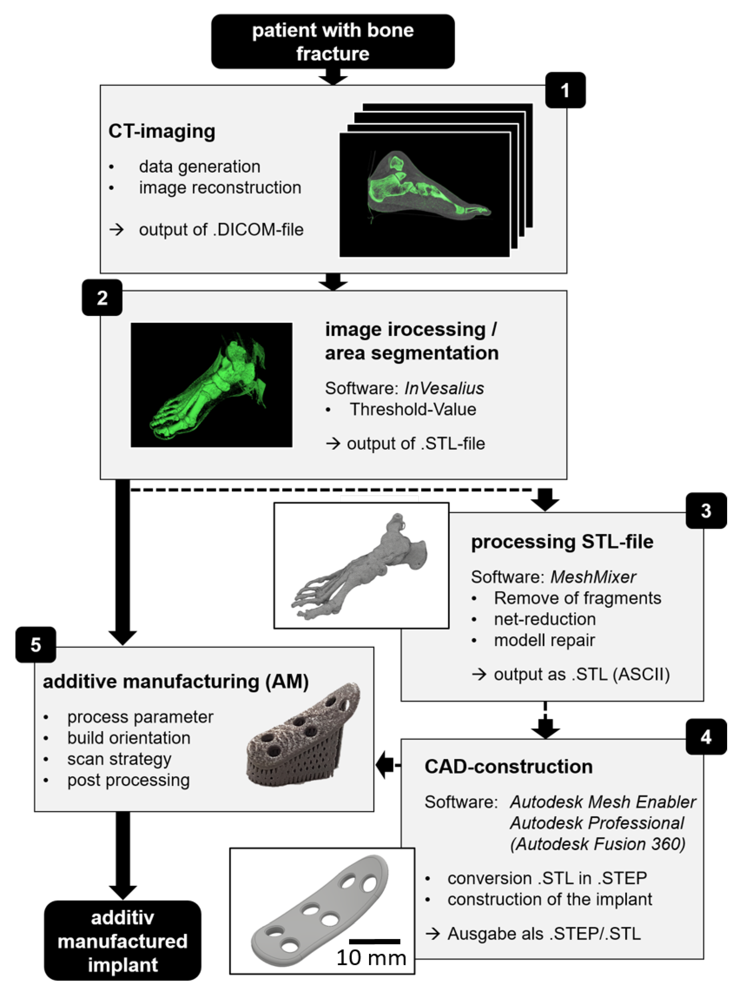
3.1. Digital Process Chain
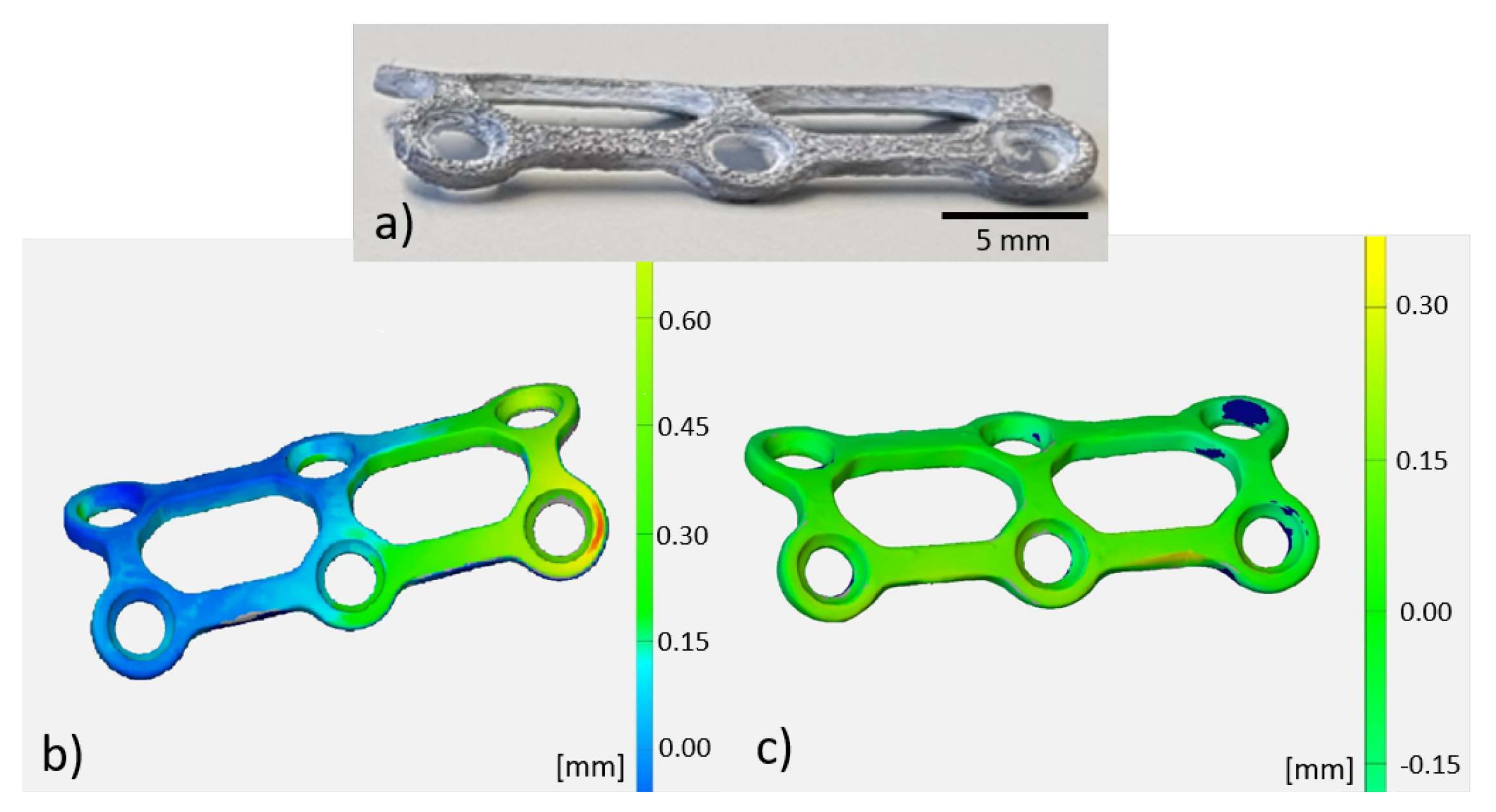
3.2. Fabrication Accuracy and Thermal Treatment
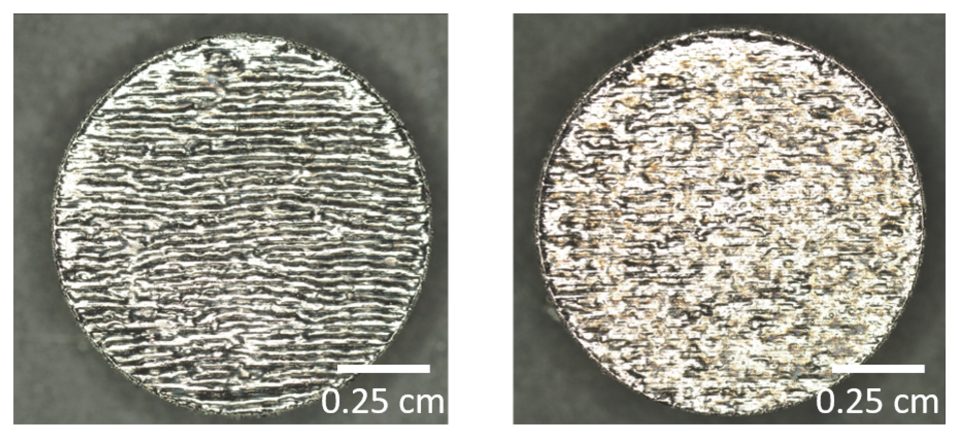
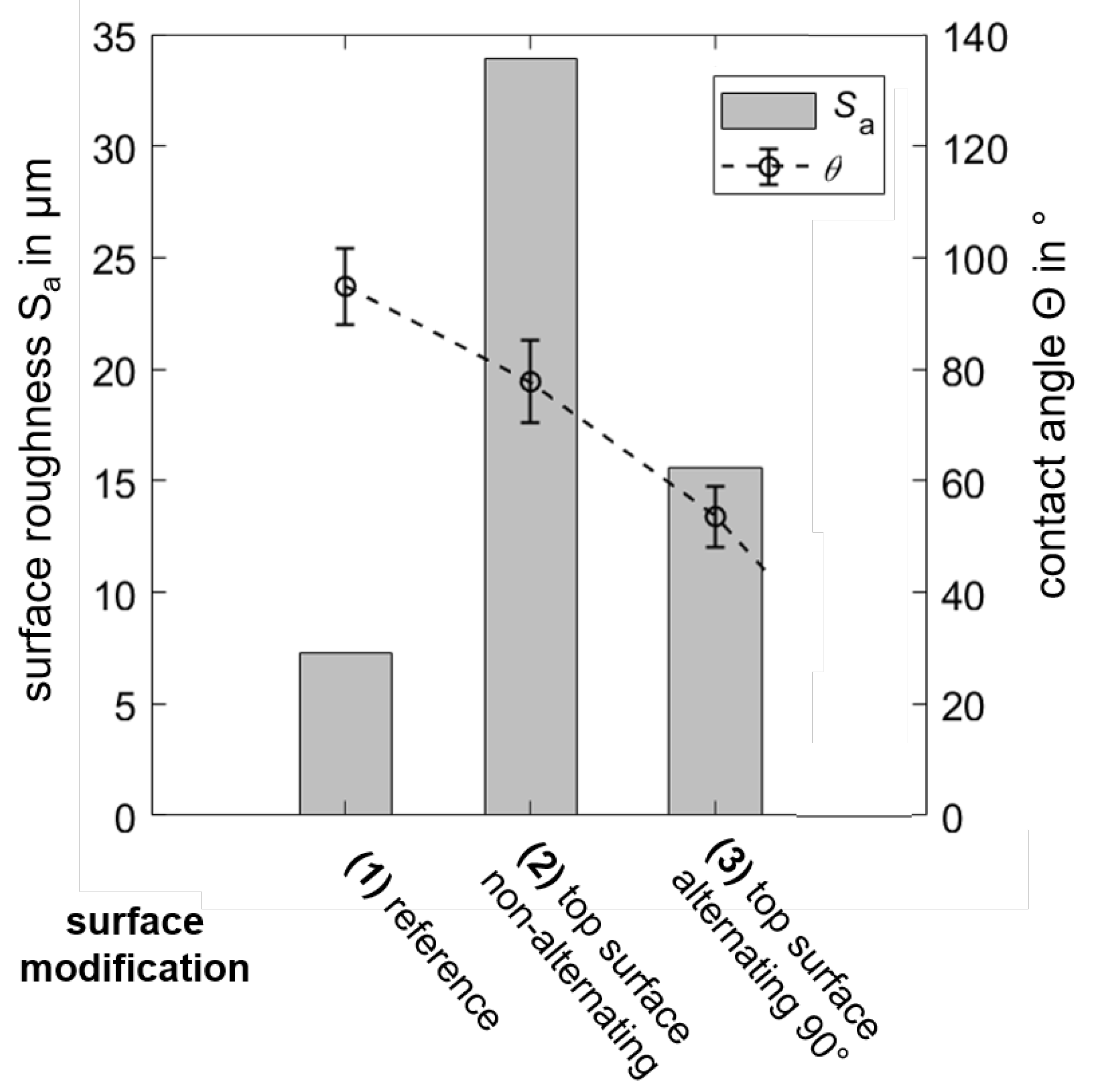
3.3. Surface Structuring and Wetting Characteristics
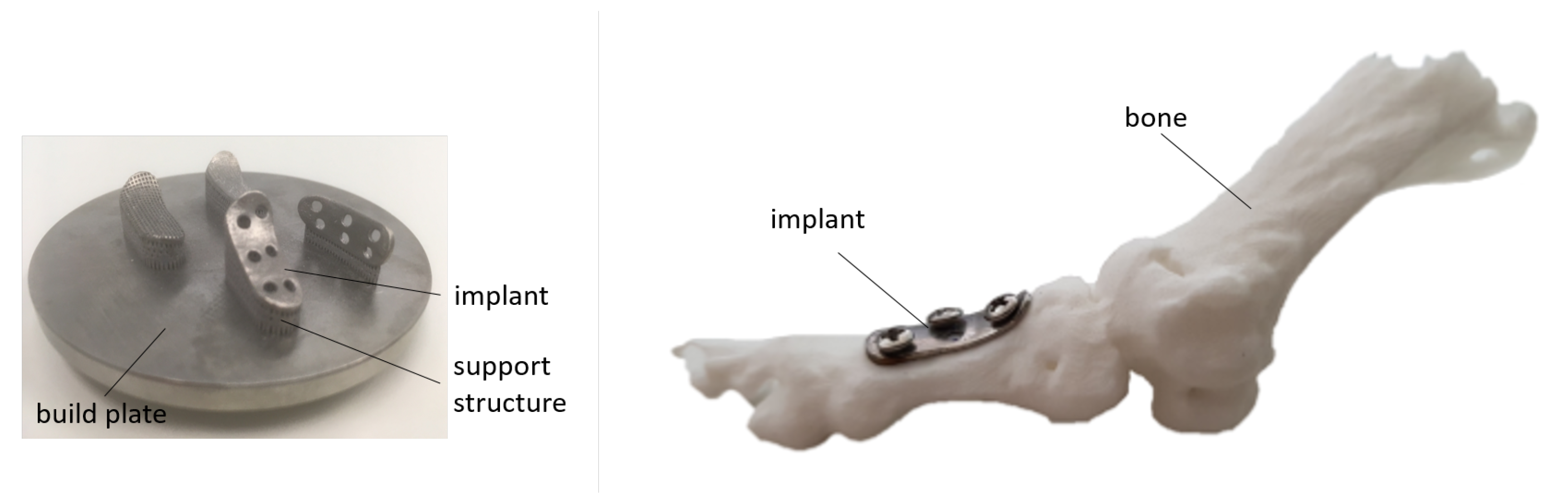
3.4. Implant Fabrication
4. Conclusions
Author Contributions
Funding
Conflicts of Interest
References
- Bedo, T.; Munteanu, S.; Popescu, I.; Chiriac, A.; Po, M.-A.; Milosan, I. Method for translating 3D bone defects into personalized implants made by additive manufacturing. Mater. Today Proc. 2019, 19, 1032–1040. [Google Scholar] [CrossRef]
- Rose, A.S.; Webster, C.E.; Harryson, O.L.; Formeister, E.J.; Rawal, R.B.; Iseli, C.E. Pre-operative simulation of pediatric mastoid surgery with 3D-printed temporal bone models. Int. J. Pediatr. Otorhinolaryngol. 2015, 79, 740–744. [Google Scholar] [CrossRef]
- Morrison, R.J.; Kashlan, K.N.; Flanangan, C.L.; Wright, J.K.; Green, G.E.; Hollister, S.J.; Weatherwax, K.J. Regulatory Considerations in the design and manufacturing of implantable 3D-printed medical devices. Clin. Transl. Sci. 2015, 8, 594–600. [Google Scholar] [CrossRef]
- Roger, A.; Shafiee, J. 3D Printing in the Biomedical Field. Encycl. Biomed. Eng. 2019, 275–280. [Google Scholar]
- Jovaid, M.; Haleem, A. Additive manufacturing applications in medical cases, a literature review. Alex. J. Med. 2017, 54, 411–422. [Google Scholar] [CrossRef]
- Negi, S.; Dhiman, S.; Sharma, R.K. Basics and applications of rapid prototyping medical models. Rapid Prototyp. J. 2014, 20, 256–267. [Google Scholar] [CrossRef]
- Haleem, A.; Jovaid, M. Role of CT and MRI in the design and development of orthopedic model using additive manufacturing. J. Clin. Orthop. Trauma. 2018, 9, 213–217. [Google Scholar] [CrossRef] [PubMed]
- Vaishya, R.; Patralekh, M.K.; Vaish, A.; Agarval, A.K.; Vijay, V. Publication trends and knowledge mapping in3D printing in orthopedics. J. Clin. Orthop. Trauma. 2018, 9, 194–201. [Google Scholar] [CrossRef] [PubMed]
- Vosniakos, G.-C.; Michael, S.; Vasileiou, A. Digital Manufacturing Process Chain for One-Off Replacement Parts: A Precision Casting Case Study. J. Manuf. Mater. Process. 2017, 1, 17. [Google Scholar] [CrossRef]
- Trombetta, R.; Inzana, J.A.; Schwarz, E.M.; Kates, S.L.; Awad, H.A. 3D printing of calcium phosphate ceramics for bone tissue engineering and drug delivery. Ann. Biomed. Eng. 2017, 45, 23–44. [Google Scholar]
- Trautmann, A.; Rüth, M.; Lemke, H.D.; Walther, T.; Hellmann, R. Two-photon polymerization based large scaffolds for adhesion and proliferation studies of human primary fibroblasts. Opt. Laser Technol. 2018, 106, 474–480. [Google Scholar] [CrossRef]
- Zamborsky, R.; Kilian, M.; Jacko, P.; Bernadic, M.; Hudak, R. Perspectives of 3D prnting technology in orthopedic surgery. Bratisl. Lek. Listy. 2019, 120, 498–504. [Google Scholar] [PubMed]
- Bartolomeu, F.; Dourado, N.; Pereira, F.; Alves, N.; Miranda, G.; Silva, F.S. Additive manufactured porous biomaterials targeting orthopedic implants: A suitable combination of mechanical, physical and topological properties. Mater. Sci. Eng. C 2020, 107, 110342. [Google Scholar] [CrossRef] [PubMed]
- Wong, T.M.; Jin, J.; Lau, T.W.; Fang, C.; Yan, C.H.; Yeung, K. The use of three-dimensional printing technology in orthopaedic surgery: A review. J. Orthop. Surg. 2017, 25, 498–504. [Google Scholar] [CrossRef]
- Wong, K.C.; Scheinemann, P. Additive manufactured metallic implants for orthopaedic applications. Sci. China Mater. 2018, 61, 440–454. [Google Scholar] [CrossRef]
- Weihu, Q.R.; Hu, Y.Y.; Yonglin, X.S.; Yang, Y.; Cai, X.K. Osteogenesis of 3D printed porous Ti6Al4V implants with different pore sizes. J. Mech. Behav. Biomed. Mater. 2018, 84, 1–11. [Google Scholar]
- Weihong, J.; Chu, P.K. Orthopedic Implants. Encycl. Biomed. Eng. 2019, 425–439. [Google Scholar]
- Zhang, B.; Pei, X.; Zhou, C.; Fan, Y.; Jiang, Q.; Ronca, A.; D’Amora, U.; Chen, Y.; Li, H.; Song, Y.; et al. The biometric design and 3D printing of customized mechanical properties porous Ti6Al4V scaffold for load-bearing bone reconstruction. Mater. Des. 2018, 152, 30–39. [Google Scholar] [CrossRef]
- Li, J.; Cui, X.; Hooper, G.J.; Lim, K.S.; Woodfield, T.B.F. Rational design, bio-functionalization and biological performance of hybrid additive manufactured titanium implants for orthopaedic applications: A review. Mater. Des. 2020, 105, 103671. [Google Scholar] [CrossRef]
- Guo, Y.; Xie, K.; Jiang, W.; Wang, L.; Li, G.; Zhao, S.; Wu, W.; Hao, Y. In vitro and in vivo study of 3D-printed porous tantalum scaffolds fir repairing bone defects. ACS Biomater. Sci. Eng. 2018, 5, 1123–1133. [Google Scholar] [CrossRef]
- Yan, X.; Li, Q.; Yin, S.; Chen, Z.; Jenkins, R.; Chen, C.; Wang, J.; Ma, W.; Bolot, R.; Lupoi, R.; et al. Mechanical and in vitro study of an isotropic Ti6Al4V lattice structure fabricated using selective laser melting. J. Alloys Compd. 2019, 782, 209–223. [Google Scholar] [CrossRef]
- Trevisan, F.; Calignano, F.; Aversa, A.; Marchese, G.; Lombardi, M.; Biamino, S.; Ugues, D.; Manfredi, D. Additive manufacturing of titanium alloys in the biomedical field: Processes, properties and applications. J. Appl. Biomater. Funct. Mater. 2018, 16, 57–67. [Google Scholar] [CrossRef] [PubMed]
- Wintermantel, E.; Ha, S.-W. Medizintechnik Life Science Engineering; Springer Science and Business Media: Berlin, Germany, 2009. [Google Scholar]
- Li, Y.; Ding, Y.; Munir, K.; Lin, J.; Brandt, M.; Atrens, A.; Xiao, Y.; Rakesh, J.; Wen, C. Novel β-Ti35Zr28Nb alloy scaffolds manufactured using selective laser melting for bone implant applications. Acta Biomater. 2019, 87, 273–284. [Google Scholar] [CrossRef]
- Schulze, C.; Weinmann, M.; Schweigel, C.; Keßler, O.; Bader, R. Mechanical properties of a newly additive manufactured implant material based on Ti-42Nb. Materials 2018, 11, 124. [Google Scholar] [CrossRef] [PubMed]
- Edelmann, A.; Riedel, L.; Hellmann, R. Realization of a dental framework by 3D printing of cobalt-chromium with superior precision and fitting accuracy. Materials 2020, 13, 5390. [Google Scholar] [CrossRef]
- Cheng, X.; Liu, S.; Chen, C.; Chen, W.; Liu, M.; Li, R.; Zhang, X.; Zhou, K. Microstructure and mechanical properties of additive manufactured porous Ti-33Nb-4Sn scaffold for orthopaedic applications. J. Mater. Sci. 2009, 30, 91. [Google Scholar] [CrossRef]
- Singare, S.; Lian, Q.; Wang, W.-P. Rapid prototyping assisted surgery planning and custom implant design. Rapid Prototyp. J. 2009, 15, 19–23. [Google Scholar] [CrossRef]
- Gubin, A.V.; Kuznetsov, V.P.; Borzunov, D.Y.; Koryukov, A.A.; Reznik, A.V.; Chevardin, A.Y. Challenges and perspectives in the use of additive technologies for making customized implants traumatology and orthopedics. Biomed. Eng. 2016, 50, 52–55. [Google Scholar] [CrossRef]
- Salmi, M.; Tuomi, J.; Paloheimo, K.-S.; Björkstrand, R.; Paloheimo, M. Patient-specific reconstruction with 3D modeling and DMLS additive manufacturing. Rapid Prototyp. J. 2012, 18, 209–214. [Google Scholar] [CrossRef]
- Poukens, J.; Laeven, P.; Beerens, M.; Nijenhuis, G.; Sloten, J.V.; Stoelinga, P.; Kessler, P. A classification of cranial implants based on the degree of difficulty in computer design and manufacture. J. Med. Robot. Comput. Assist. Surg. 2008, 4, 46–50. [Google Scholar] [CrossRef]
- Probst, F.A.; Hutmacher, D.W.; Müller, D.F.; Machens, H.G.; Schantz, J.-T. Calvarial reconstruction by customized bioactive implant. Handchir. Mikrochir. Plast. Chir. 2010, 42, 369–373. [Google Scholar] [CrossRef] [PubMed]
- Rouse, S. At the speed of light-additive manufacturing of custom medical implants. TCT Mag. 2009, 17, 47–50. [Google Scholar]
- Brecher, C. Advances in Production Technology; Springer: Heidelberg, Germany, 2015. [Google Scholar]
- Thijs, L.; Verhaeghe, F.; Craeghs, T.; van Humbeeck, J.; Kruth, J.-P. A study of microstructural evolution during selective laser melting of Ti-6Al-4V. Acta Mater. 2010, 58, 3303–3312. [Google Scholar] [CrossRef]
- Attar, H.; Calin, M.; Zhang, L.C.; Scudino, S.; Eckert, J. Manufacture by selective laser melting and mechanical behavior of commercially pure titanium. Mater. Sci. Eng. A 2014, 593, 170–177. [Google Scholar] [CrossRef]
- Nguyen, Q.B.; Nai, M.L.S.; Zhu, Z.; Sun, C.N.; Wei, J.; Zhou, W. Characteristics of Inconel Powders for Powder-Bed Additive Manufacturing. Engineering 2017, 3, 695–700. [Google Scholar] [CrossRef]
- Clayton, J. Optimising metal powders for additive manufacturing. Metal Powder Rep. 2014, 69, 14–17. [Google Scholar] [CrossRef]
- Lee, Y.S.; Zhang, W. Mesoscopic simulation of heat transfer and fluid flow in laser powder bed additive manufacturing. In Proceedings of the International Solid Free Form Fabrication Symposium, Austin, TX, USA, 10–12 August 2015. [Google Scholar]
- Karapatis, N.P.; Egger, G.; Gygax, P.E.; Glardon, R. Optimization of powder layer density in selective laser sintering. In Proceedings of the International Solid Free Form Fabrication Symposium, Austin, TX, USA, 9–11 August 1999. [Google Scholar]
- Spierings, A.B.; Levy, G. Comparision of density of stainless steel 316L parts produced with selective laser melting using different powder grades. In Proceedings of the Annual International Solid Freeform Fabrication Symposium, Austin, TX, USA, 3–5 August 2009. [Google Scholar]
- Gopalan, P.; Kandlikar, S.G. Contact line characteristics of liquid-gas interfaces over grooved surfaces. Microfluid. Nanofluidics 2014, 16, 999–1008. [Google Scholar] [CrossRef]
- Young, T. An essay on the cohesion of fluids. Philos. Trans. R. Soc. Lond. 1805, 95, 65–87. [Google Scholar]
- Camilo, A.A.; Amorim, P.H.; de Moraes, T.F.; Azevedo, F.D.S.; da Silva, J.V. InVesalius: Medical image edition. In Proceedings of the 1st International Conference on Design and Processes for Medical Devices, Brescia, Italy, 2–4 May 2012; pp. 279–282. [Google Scholar]
- Wysocki, B.; Maj, P.; Krawczynska, A.; Rozniatowski, K.; Zduneka, J.; Kurzydłowski, K.J.; Swieszkowski, W. Microstructure and mechanical properties investigation of CP titanium processed by selective laser melting (SLM). J. Mater. Process. Technol. 2017, 241, 13–23. [Google Scholar] [CrossRef]
- van Ta, D.; Dunn, A.; Wasley, T.J.; Li, J.; Kay, R.W.; Stringer, J.; Smith, P.J.; Esenturk, E.; Connaughton, C.; Shephard, J.D. Laser textured surface gradients. Appl. Surf. Sci. 2016, 371, 583–589. [Google Scholar]
- van Ta, D.; Dunn, A.; Wasley, T.J.; Li, J.; Kay, R.W.; Stringer, J.; Smith, P.J.; Esenturk, E.; Connaughton, C.; Shephard, J.D. Laser textured superhydrophobic surfaces and their applications for homogeneous spot deposition. Appl. Surf. Sci. 2016, 365, 153–159. [Google Scholar]


| Energy Density (J/) | Laser Power (W) | Hatch Distance (μm) | |
|---|---|---|---|
| area | 171 | 85.6 | 0.08 |
| contour | 96 | 30.2 | 0.05 |
| support | 6 | 35.8 | — |
| DIN 5832-2 | ||||
|---|---|---|---|---|
| tensile strength [N/mm2] | 550 | |||
| failure strain [%] | 15 |
Publisher’s Note: MDPI stays neutral with regard to jurisdictional claims in published maps and institutional affiliations. |
© 2020 by the authors. Licensee MDPI, Basel, Switzerland. This article is an open access article distributed under the terms and conditions of the Creative Commons Attribution (CC BY) license (http://creativecommons.org/licenses/by/4.0/).
Share and Cite
Edelmann, A.; Dubis, M.; Hellmann, R. Selective Laser Melting of Patient Individualized Osteosynthesis Plates—Digital to Physical Process Chain. Materials 2020, 13, 5786. https://doi.org/10.3390/ma13245786
Edelmann A, Dubis M, Hellmann R. Selective Laser Melting of Patient Individualized Osteosynthesis Plates—Digital to Physical Process Chain. Materials. 2020; 13(24):5786. https://doi.org/10.3390/ma13245786
Chicago/Turabian StyleEdelmann, André, Monique Dubis, and Ralf Hellmann. 2020. "Selective Laser Melting of Patient Individualized Osteosynthesis Plates—Digital to Physical Process Chain" Materials 13, no. 24: 5786. https://doi.org/10.3390/ma13245786
APA StyleEdelmann, A., Dubis, M., & Hellmann, R. (2020). Selective Laser Melting of Patient Individualized Osteosynthesis Plates—Digital to Physical Process Chain. Materials, 13(24), 5786. https://doi.org/10.3390/ma13245786