Ultrasound-Assisted Through-Mask Electrochemical Machining of Hole Arrays in ODS Superalloy

Abstract
1. Introduction
2. Numerical Analysis of Ultrasound-Assisted TMECM
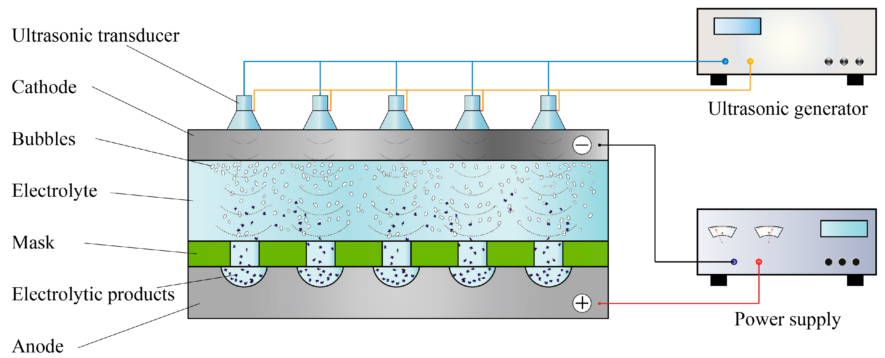
2.1. Principles of Ultrasound-Assisted TMECM
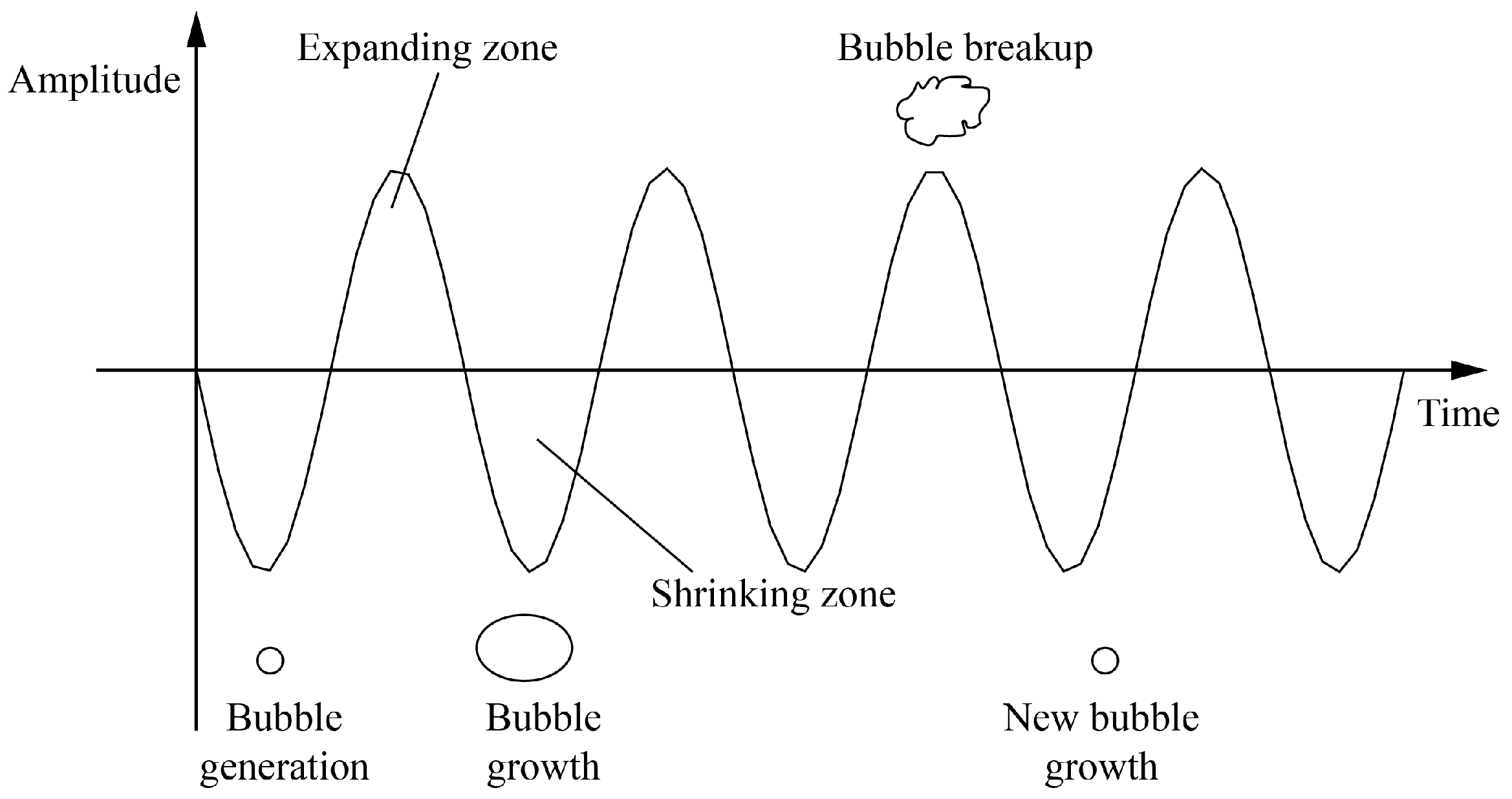
2.2. Principle of Ultrasonic Cavitation
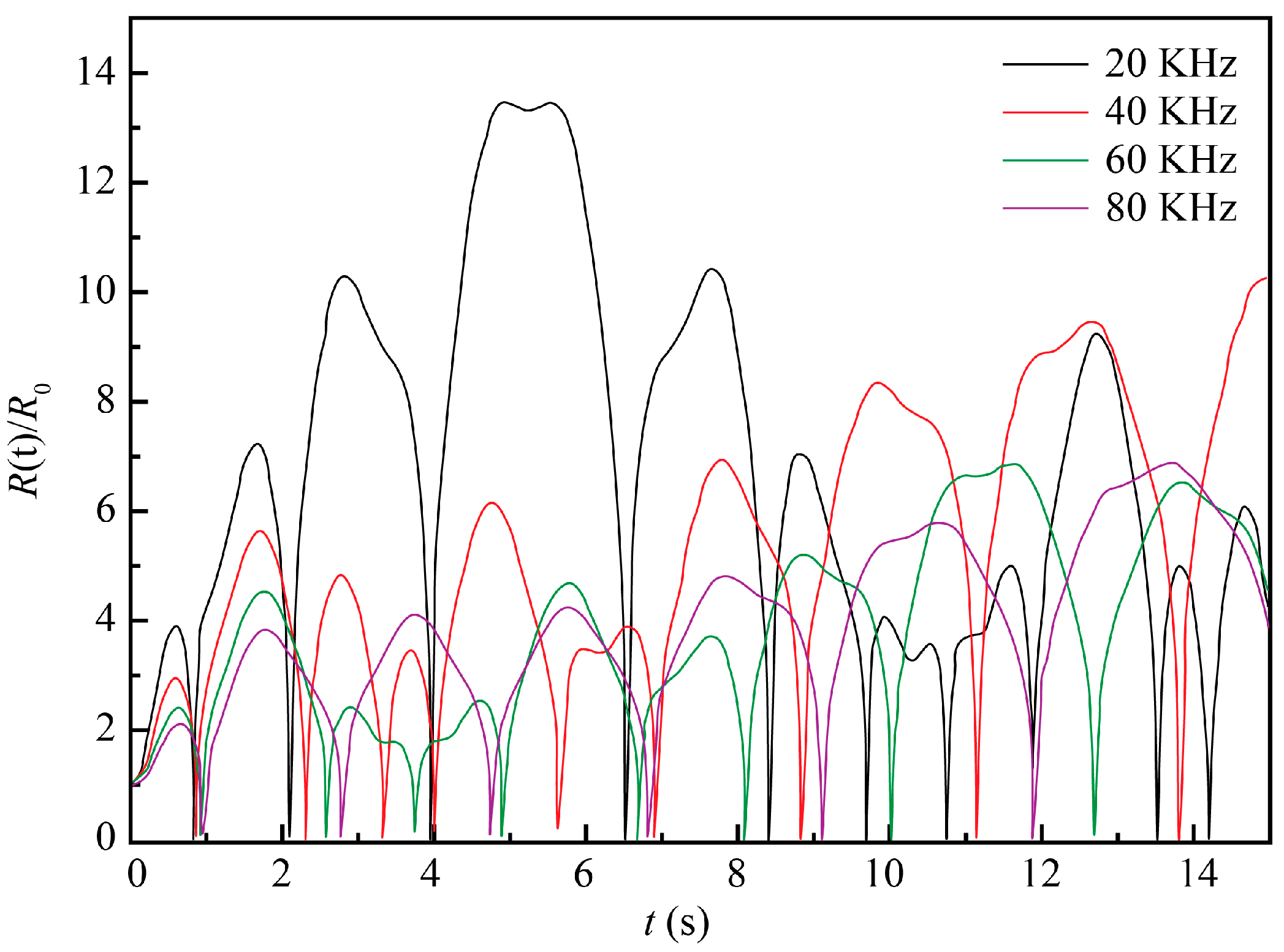
2.2.1. Influence of Ultrasound Parameters
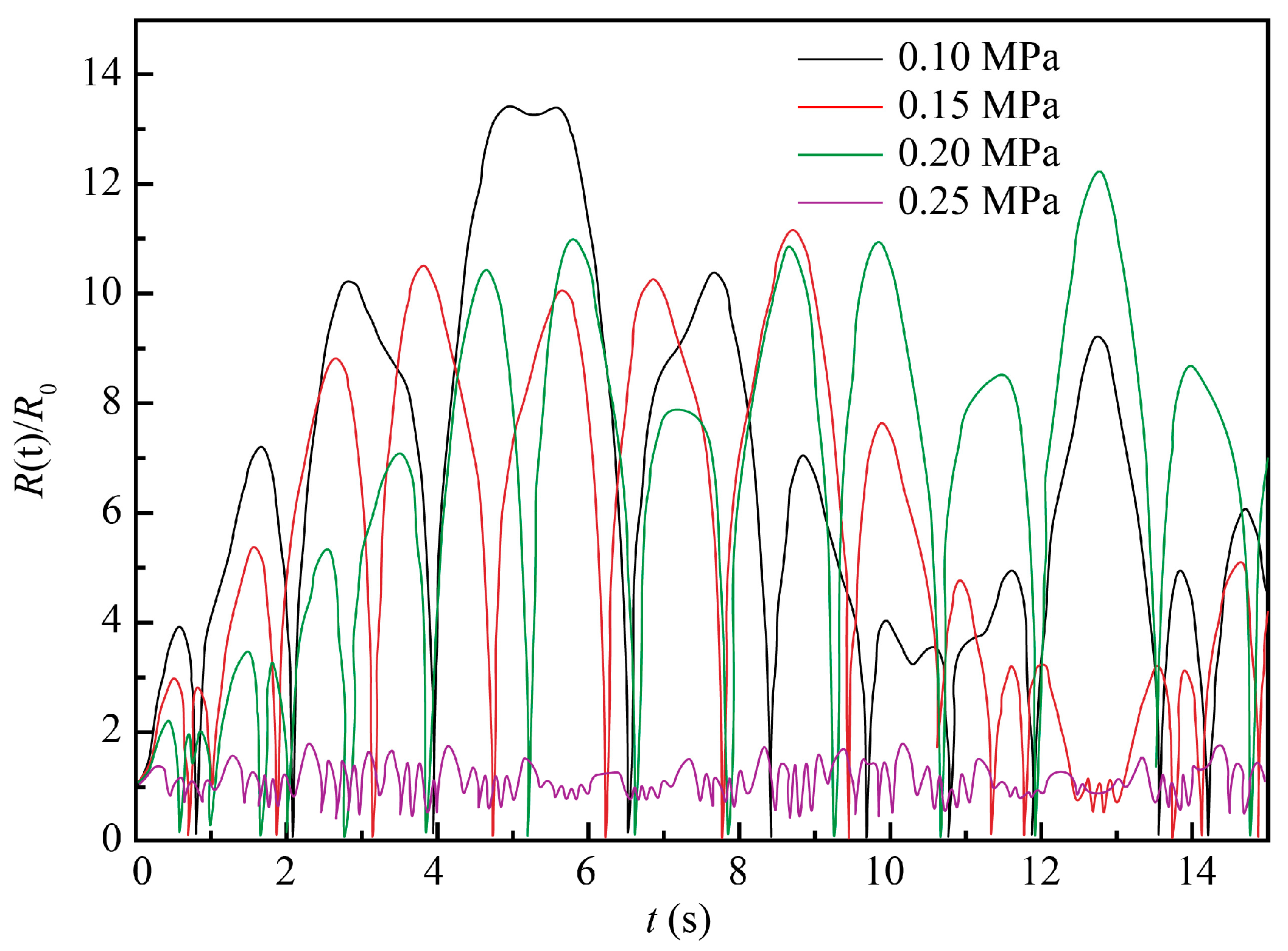
2.2.2. Influence of Pressure of Electrolyte Solution
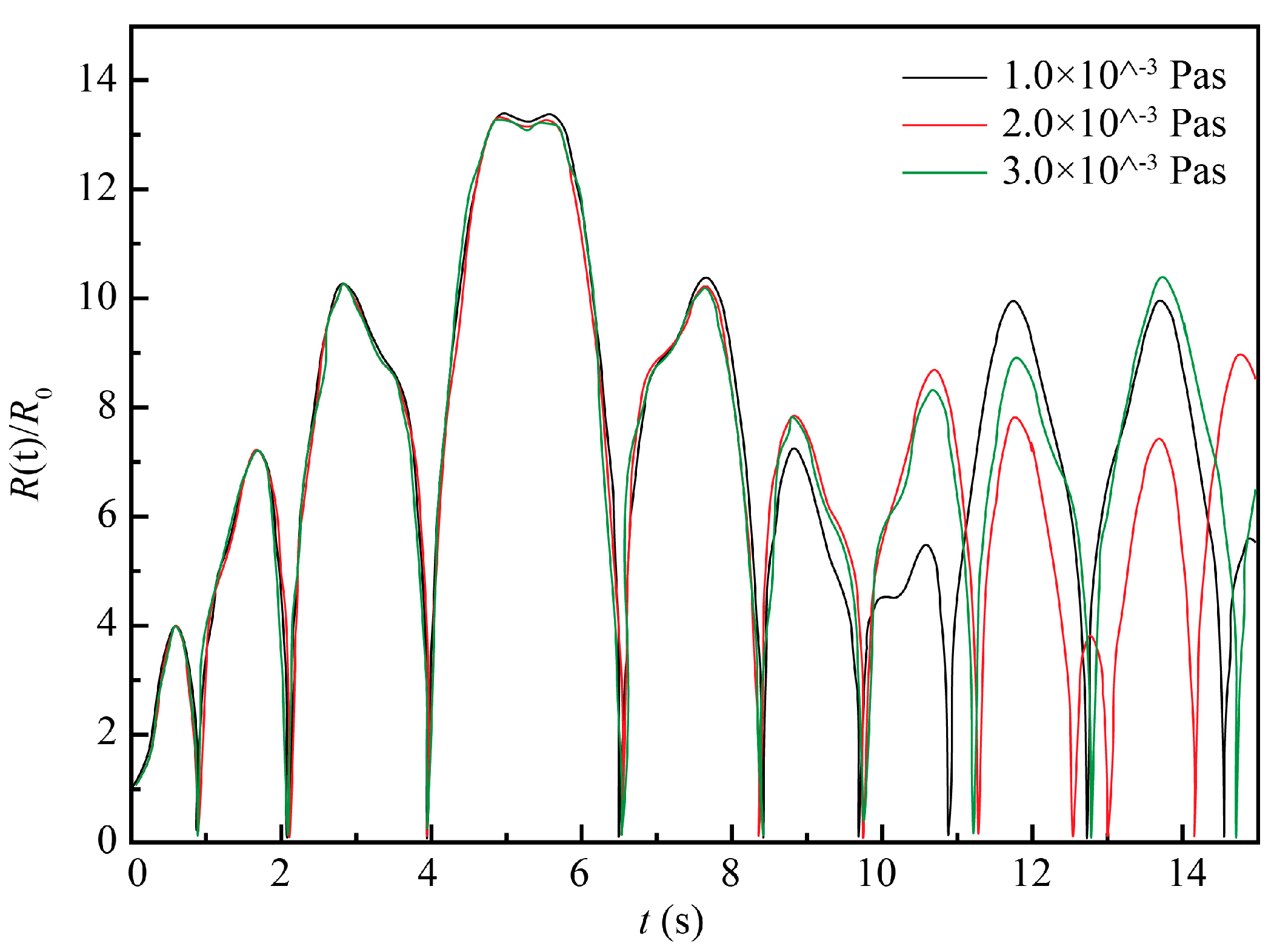
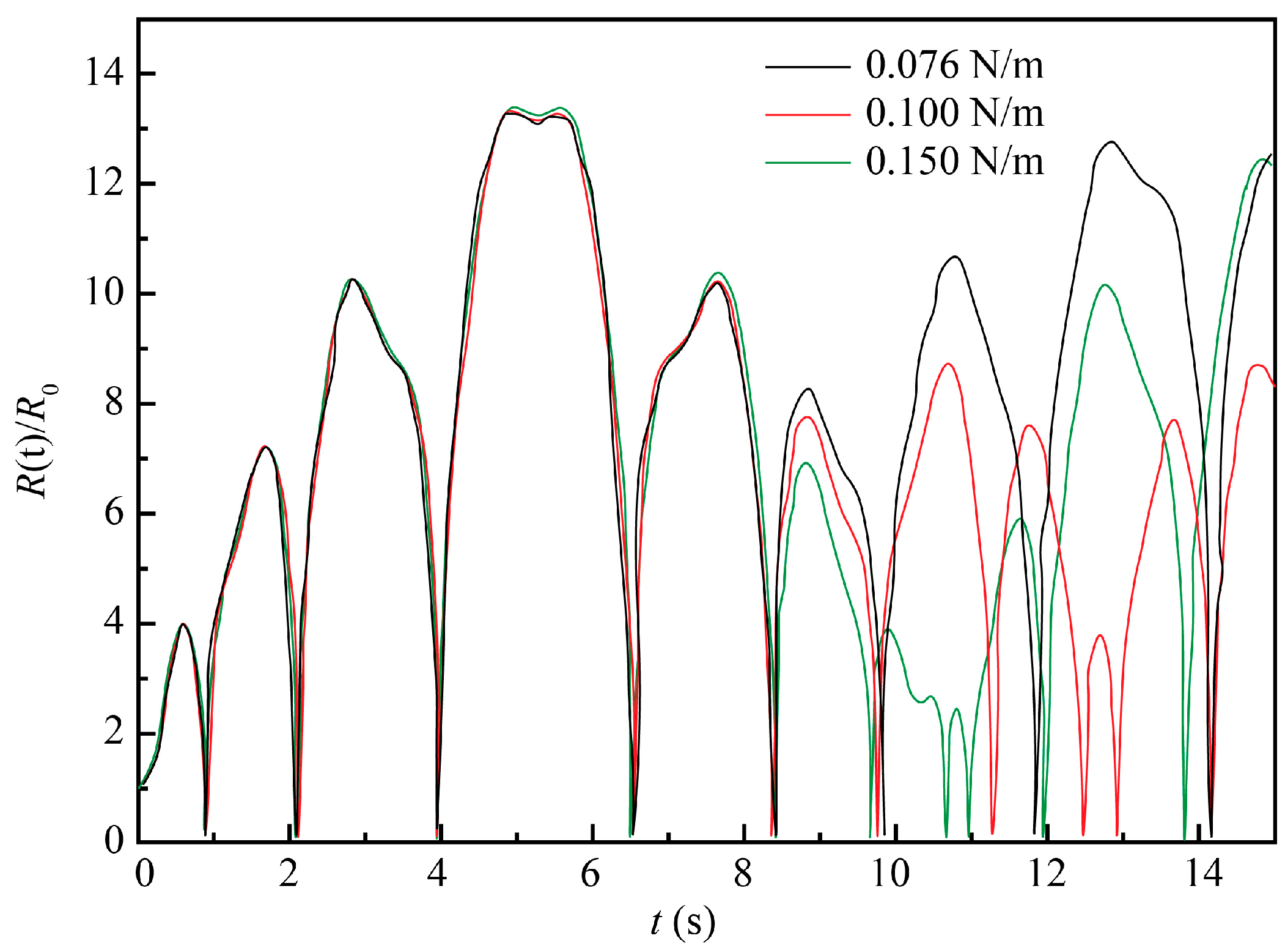
2.2.3. Influence of Viscosity and Surface Tension Coefficients
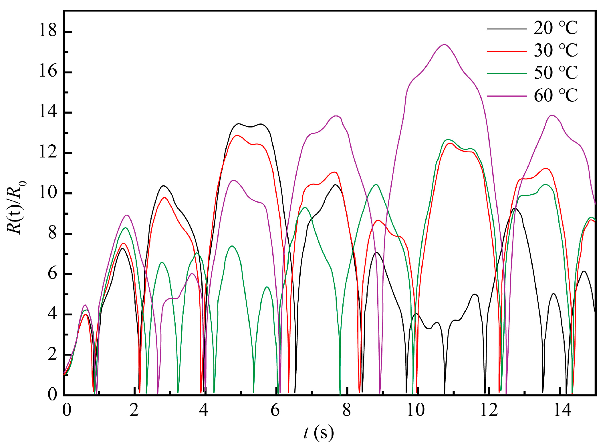
2.2.4. Influence of the ECM System Temperature
3. Experimental
3.1. The Anode Material
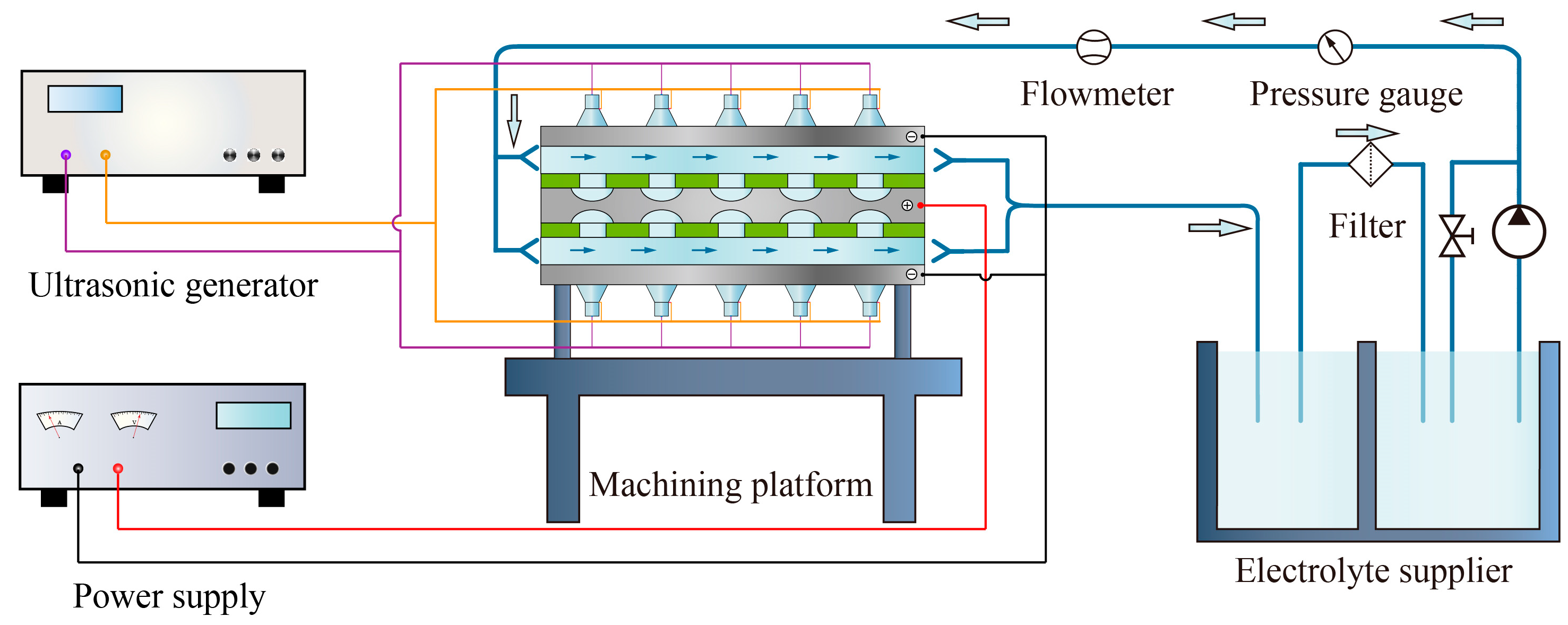
3.2. Experimental Setup
4. Results and Discussion
4.1. Experiment Investigation on Parameters
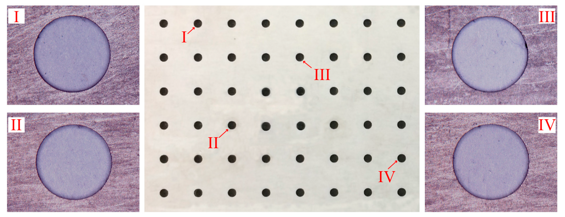
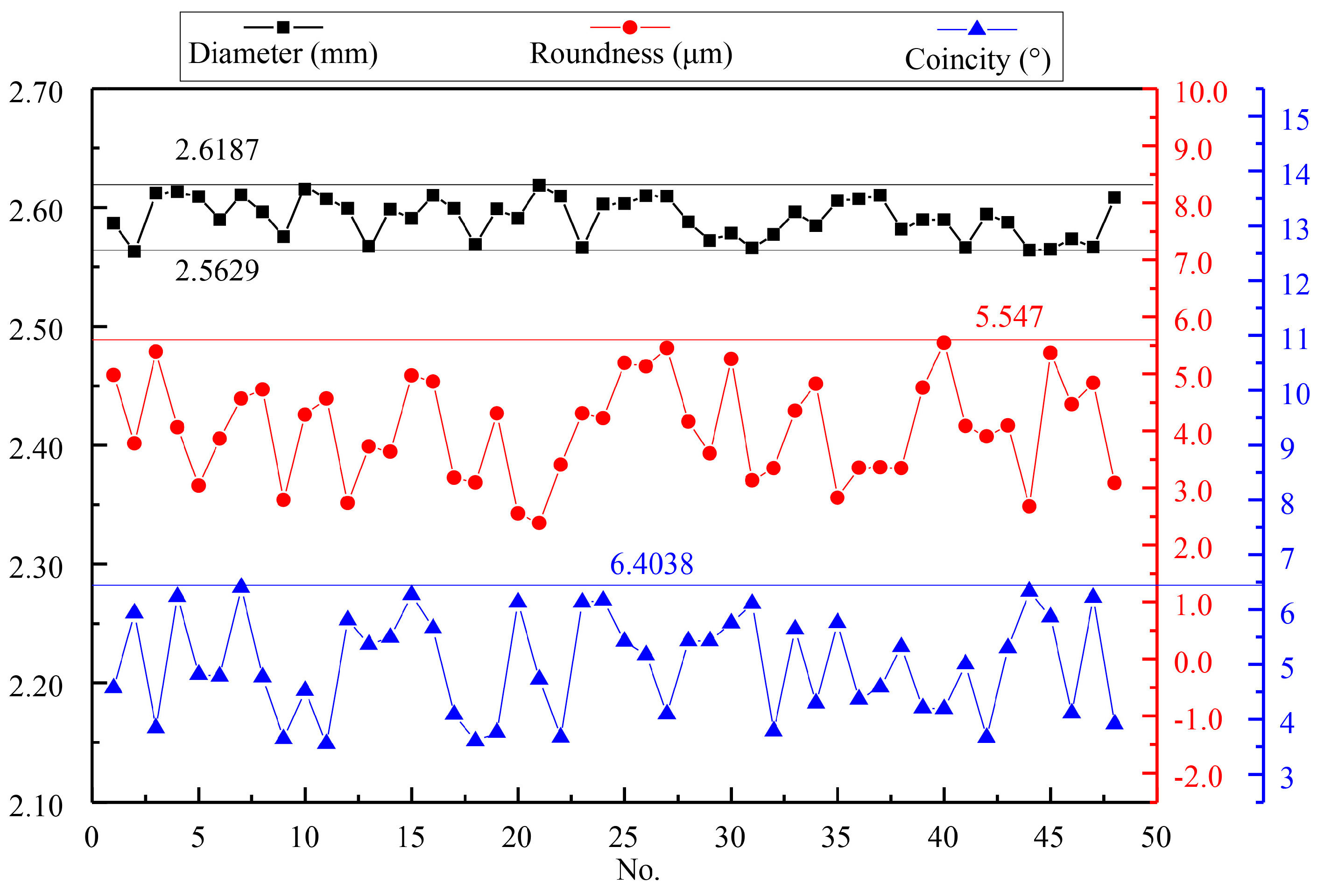
4.2. Experiment Investigation on Hole Array Structure
5. Conclusions
Author Contributions
Funding
Acknowledgments
Conflicts of Interest
References
- Gachot, C.; Rosenkranz, A.; Hsu, S.M.; Costa, H. A critical assessment of surface texturing for friction and wear improvement. Wear 2017, 372–373, 21–41. [Google Scholar] [CrossRef]
- Xu, Z.; Wang, Y. Electrochemical machining of complex components of aero-engines: Developments, trends, and technological advances. Chin. J. Aeronaut. 2019. [Google Scholar] [CrossRef]
- Zhang, X.; Tnay, G.L.; Liu, K.; Kumar, A.S. Effect of apex offset inconsistency on hole straightness deviation in deep hole gun drilling of Inconel 718. Int. J. Mach. Tools Manuf. 2018, 125, 123–132. [Google Scholar] [CrossRef]
- Hauschwitz, P.; Stoklasa, B.; Brajer, J.; Kuchařík, J.; TurČiČová, H.; Písařík, M.; Rostohar, D.; Mocek, T.; Duda, M.; Lucianetti, A. Micromachining of Invar with 784 Beams Using 1.3ps Laser Source at 515 nm. Materials 2020, 13, 2962. [Google Scholar] [CrossRef] [PubMed]
- Chang, D.Y.; Lin, C.H. High-aspect ratio mechanical microdrilling process for a microhole array of nitride ceramics. Int. J. Adv. Manuf. Technol. 2018, 100, 2867–2883. [Google Scholar] [CrossRef]
- Li, G.; Natsu, W.; Yu, Z. Study on quantitative estimation of bubble behavior in micro hole drilling with EDM. Int. J. Mach. Tools Manuf. 2019, 146, 103437. [Google Scholar] [CrossRef]
- Rahman, Z.; Das, A.K.; Chattopadhyaya, S. Microhole drilling through electrochemical processes: A review. Mater. Manuf. Process. 2018, 33, 1379–1405. [Google Scholar] [CrossRef]
- Soundarrajan, M.; Thanigaivelan, R. Investigation on Electrochemical Micromachining (ECMM) of Copper Inorganic Material Using UV Heated Electrolyte. Russ. J. Appl. Chem. 2018, 91, 1805–1813. [Google Scholar] [CrossRef]
- Baldhoff, T.; Nock, V.; Marshall, A.T. Review—Through-Mask Electrochemical Micromachining. J. Electrochem. Soc. 2018, 165, E841–E855. [Google Scholar] [CrossRef]
- Li, H.S.; Wang, G.Q.; Li, L.W.; Gao, C.P.; Qu, N.; Zhu, D. Through-mask electrochemical machining of hole arrays on molybdenum sheets. Int. J. Adv. Manuf. Technol. 2017, 93, 2393–2401. [Google Scholar] [CrossRef]
- Wang, G.Q.; Li, H.S.; Qu, N.S.; Zhu, D. Investigation of the hole-formation process during double-sided through-mask electrochemical machining. J. Mater. Process. Technol. 2016, 234, 95–101. [Google Scholar] [CrossRef]
- Kunar, S.; Bhattacharyya, B. Electrochemical micromachining of micro square pattern using reusable masked tool. Adv. Manuf. Process. 2019, 34, 487–493. [Google Scholar] [CrossRef]
- Mahata, S.; Kunar, S.; Bhattacharyya, B. Micro Dimple Array Fabrication by Through Mask Electrochemical Micromachining Utilizing Low-Aspect Ratio Mask. J. Electrochem. Soc. 2018, 165, E129–E137. [Google Scholar] [CrossRef]
- Pa, P.S. Electrode form design of large holes of die material in ultrasonic electrochemical finishing. J. Mater. Process. Technol. 2007, 192, 470–477. [Google Scholar] [CrossRef]
- Bhattacharyya, B.; Malapati, M.; Munda, J.; Sarkar, A. Influence of tool vibration on machining performance in electrochemical micro-machining of copper. Int. J. Mach. Tools Manuf. 2007, 47, 335–342. [Google Scholar] [CrossRef]
- Patel, J.B.; Feng, Z.; Villanueva, P.P.; Hung, W.N. Quality Enhancement with Ultrasonic Wave and Pulsed Current in Electrochemical Machining. Procedia Manuf. 2017, 10, 662–673. [Google Scholar] [CrossRef]
- Zhu, X.; Liu, Y.; Zhang, J.; Wang, K.; Kong, H. Ultrasonic-assisted electrochemical drill-grinding of small holes with high-quality. J. Adv. Res. 2020, 23, 151–161. [Google Scholar] [CrossRef]
- Wang, Q.D.; Cai, X.X.; Wang, L.; Li, P.; Xiao, J.; Li, Y. Investigation of the influence of ultrasonic stirring on mass transfer in the through-mask electrochemical micromachining process. Sci. China Technol. Sci. 2018, 61, 1–7. [Google Scholar] [CrossRef]
- Peshkovsky, S.L.; Peshkovsky, A.S. Shock-wave model of acoustic cavitation. Ultrason. Sonochemistry 2008, 15, 618–628. [Google Scholar] [CrossRef]
- Allen, J.S.; Roy, R.A. Dynamics of gas bubbles in viscoelastic fluids. I. Linear viscoelasticity. J. Acoust. Soc. Am. 2000, 107, 3167–3178. [Google Scholar] [CrossRef]
- Colussi, A.J.; Weavers, L.K.; Hoffmann, M.R. Chemical Bubble Dynamics and Quantitative Sonochemistry. J. Phys. Chem. A 1998, 102, 6927–6934. [Google Scholar] [CrossRef]
- Hilgenfeldt, S.; Brenner, M.P.; Grossmann, S.; Lohse, D. Analysis of Rayleigh-Plesset dynamics for sonoluminescing bubbles. J. Fluid Mech. 2017, 365, 171–204. [Google Scholar] [CrossRef]
- Osterman, A.; Dular, M.; Sirok, B. Numerical simulation of a near-wall bubble collapse in an ultrasonic field. J. Fluid Sci. Technol. 2009, 4, 210–221. [Google Scholar] [CrossRef]


| Temperature (°C) | Viscosity Coefficient (×10−3 Pa∙s) | Surface Tension (N/m) | Vapor Pressure (Pa) |
|---|---|---|---|
| 20 | 1.153 | 0.0760 | 2.34 × 10³ |
| 30 | 0.950 | 0.0745 | 4.25 × 10³ |
| 50 | 0.670 | 0.0715 | 1.23 × 10⁴ |
| 60 | 0.570 | 0.0700 | 1.99 × 10⁴ |
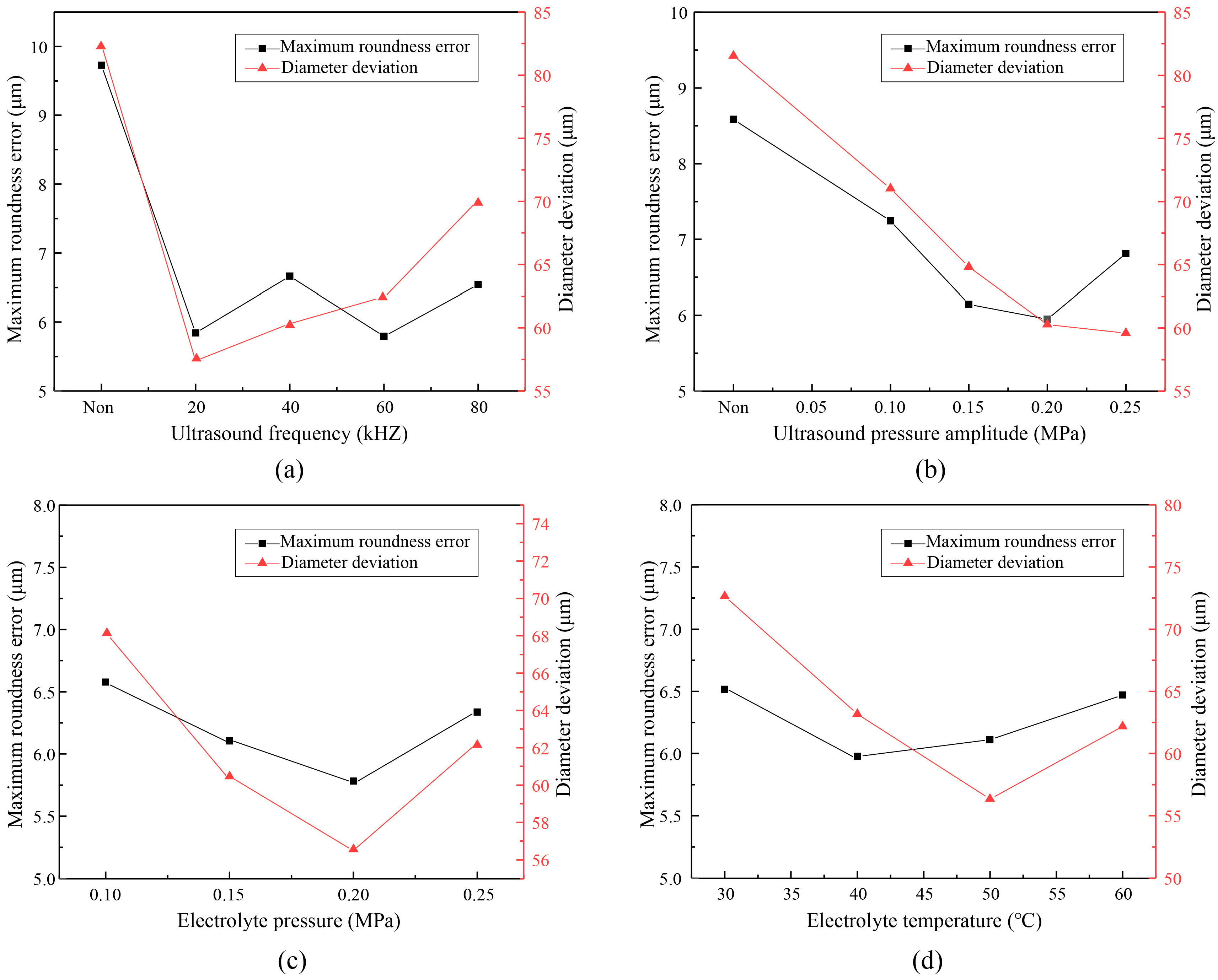
| Measurement Index | Ultrasonic Frequency (kHz) | Electrolyte Pressure (MPa) | |||||||
|---|---|---|---|---|---|---|---|---|---|
| Non | 20 | 40 | 60 | 80 | 0.10 | 0.15 | 0.20 | 0.25 | |
| Maximum roundness error (μm) | 9.726 | 5.844 | 6.663 | 5.793 | 6.542 | 6.578 | 6.104 | 5.781 | 6.337 |
| Diameter deviation (μm) | 82.4 | 57.3 | 60.3 | 62.5 | 70.1 | 68.3 | 60.5 | 56.6 | 62.2 |
| Measurement index | Ultrasonic pressure amplitude (MPa) | Electrolyte temperature (°C) | |||||||
| Non | 0.10 | 0.15 | 0.20 | 0.25 | 30 | 40 | 50 | 60 | |
| Maximum roundness error (μm) | 8.584 | 7.245 | 6.144 | 5.951 | 6.811 | 6.064 | 5.976 | 6.110 | 6.471 |
| Diameter deviation (μm) | 81.5 | 71.0 | 64.8 | 60.3 | 59.6 | 72.6 | 63.2 | 56.4 | 62.3 |
| Parameter | Value |
|---|---|
| The anode metal | MA956 |
| Voltage, V | 25 |
| Electric current efficiency, % | 100 |
| Frequency of pulse power supply, Hz | 400 |
| Duty ratio of pulse power supply, % | 20 |
| Temperature of the electrolyte, °C | 50 |
| Pressure of the electrolyte, MPa | 0.2 |
Publisher’s Note: MDPI stays neutral with regard to jurisdictional claims in published maps and institutional affiliations. |
© 2020 by the authors. Licensee MDPI, Basel, Switzerland. This article is an open access article distributed under the terms and conditions of the Creative Commons Attribution (CC BY) license (http://creativecommons.org/licenses/by/4.0/).
Share and Cite
Wang, G.; Zhang, Y.; Li, H.; Tang, J. Ultrasound-Assisted Through-Mask Electrochemical Machining of Hole Arrays in ODS Superalloy. Materials 2020, 13, 5780. https://doi.org/10.3390/ma13245780
Wang G, Zhang Y, Li H, Tang J. Ultrasound-Assisted Through-Mask Electrochemical Machining of Hole Arrays in ODS Superalloy. Materials. 2020; 13(24):5780. https://doi.org/10.3390/ma13245780
Chicago/Turabian StyleWang, Guoqian, Yan Zhang, Hansong Li, and Jian Tang. 2020. "Ultrasound-Assisted Through-Mask Electrochemical Machining of Hole Arrays in ODS Superalloy" Materials 13, no. 24: 5780. https://doi.org/10.3390/ma13245780
APA StyleWang, G., Zhang, Y., Li, H., & Tang, J. (2020). Ultrasound-Assisted Through-Mask Electrochemical Machining of Hole Arrays in ODS Superalloy. Materials, 13(24), 5780. https://doi.org/10.3390/ma13245780