Article

Floor Vibration Experiment and Serviceability Test of iFLASH System

1
Department of Architecture, Seoul National University of Science & Technology, 232, Gongneung-ro, Nowon-gu, Seoul 01811, Korea
2
Department of Civil, Environmental and Architectural Engineering, Korea University, Seoul 02841, Korea
*
Author to whom correspondence should be addressed.
Materials 2020, 13(24), 5760; https://doi.org/10.3390/ma13245760
Submission received: 27 November 2020 / Revised: 14 December 2020 / Accepted: 15 December 2020 / Published: 17 December 2020
(This article belongs to the Special Issue Novel High-Performance Building Materials and Structures)

Abstract

:
Studies on novel composite structures that can decrease floor height and improve constructional efficiency in order to increase spatial efficiency and lease revenue have been actively conducted. An innovative fire-proof, lightweight, absorbed, shallow, and hybrid (iFLASH) system was developed to solve construction site issues, such as improving constructability, reducing construction time, and attaining structural efficiency by reducing the weight of the building structure. This system can shorten the construction duration and decrease the floor height and structural weight, owing to features such as a low thickness and light weight. However, studies on the vibration characteristics of this new floor system have not been performed yet. As the general thickness of the iFLASH system ranges from 25 to 30 mm, it must have a sufficient floor vibration performance in order to be utilized. To evaluate the floor vibration performance of the iFLASH system, an experiment was performed in two buildings where the system was applied. This paper presents the results of the dynamic characteristics and serviceability testing as basic data for the vibration characteristics of the iFLASH system.

1. Introduction

High-rise buildings are increasingly defining the architecture of modern society due to an increase in the urban population and facility intensification. Accordingly, studies on novel composite structures have been actively conducted for floor-height reduction and to improve constructional efficiency, thereby increasing spatial efficiency and lease revenue [1,2,3].
The iTECH composite beam [4], TSC composite beam [5], MHS composite beam, and Smart beam [6] in Korea, and a deep deck with an asymmetric beam, Flex Fram [7], and Slim Floor [8] with Half PC were developed to decrease the floor height and improve serviceability in the United States and Europe. However, the system possessed a constructability issue, i.e., the beams had to be embedded inside the slab, thus complicating the structure. Precast concrete (PC) construction resolved this problem by shortening the construction duration and improving the constructional efficiency by decreasing the production of molding compositions and the amount of cast-in-place concrete.
However, some limitations remain, such as the heavy weight, the concrete-topping placement, and the need for skilled workers to install joint connections. In particular, the PC method possesses a drawback of low economic feasibility, in contrast to the cast-in-place method, owing to the additional costs resulting from the extra processes and freight charges.
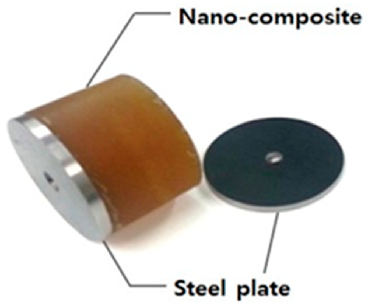
Therefore, this study investigated the vibration characteristics of a novel floor system that attains structural efficiency by improving constructability, shortening the construction duration, and reducing the self-weight. The novel floor system investigated is an innovative, fire-proof, lightweight, absorbed, shallow, and hybrid system, i.e., the iFLASH system [9], consisting of a nano-composite between the upper and lower steel plates, as shown in Figure 1.
The nano-composite, with a high bond strength performance, allows this system to exhibit a high bending resistance and reduced self-weight. This is possible because it has a lower density than conventional structural materials. This nano-composite is a type of polymer classified as a polyurethane that is produced with a diisocyanate–polyol mixture. The density of this new material is 1178 kg/m3; other mechanical properties of this material are listed in Table 1. Owing to the large rupture strain and high bond strength, this nano-composite can be used in structural elements with steel plates as the iFLASH system.
The system used both bolted joints as well as welding for installation on buildings, and this decreased the construction duration, floor height, and structural weight owing to the low-thickness and lightweight features [10].
Bond strength was a significant factor for securing the structural performance of the module, and it facilitates the demonstration of a fully composite behavior for the iFLASH system even under high deformation [10].
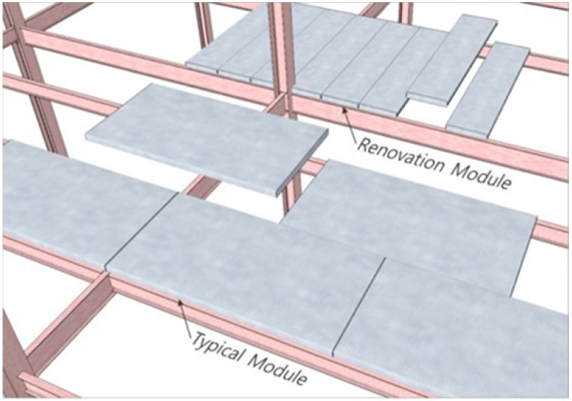
The sizes of a typical module and a renovation module of the iFLASH system are shown in Figure 2. A typical large module with an approximate area of 15 m2 was appropriate for a new building. A small renovation module with an approximate area of 1.5 m2 was appropriate for a human to lift [10].
This study mainly investigated the vibration characteristics of the renovation module of the iFLASH system. The international criteria for the serviceability evaluation of floor vibration include housing performance [11,12,13,14].
In the criteria specified in [11,12,13,14], the floor’s damping ratio was considered, and high values for vibration criteria were allowed as the damping ratio was increased for floor vibration evaluation. In the American Institute of Steel Construction (AISC) design guide [15], the damping ratio of the steel frame floor slab was suggested to be between 2 and 5% [16].
However, the steel house with a 1 mm (±) surface treatment using light gauge steel that was widely used in the USA and Australia had many partition walls connected to the ceiling height; a screw was used rather than welding, and a high-strength bolt, different from that used in the office steel-frame building, was also used. For this reason, the damping ratio of the walking vibration for the steel house was 9.14%. This value is higher than the 2–5% damping ratio of the steel-frame office buildings. As shown above, the damping ratio varied significantly according to the steel-frame system [16].
Recently, there have been attempts to use the iFLASH system instead of the deck plate slab of an existing steel frame. It is known that this system has many advantages, such as the constructability being comparable to that of deck plate slabs, the lower construction expenses due to the 10% decreased structural weight and 25% reduced construction duration, and economic efficiency [17].
In terms of flexural performance, the iFLASH system exhibits fully composite behavior under large deformations [18], because of the high strength of the bond between the nano-composite and steel plates and the high ductility of the nano-composite. Thus, the upper and lower steel plates in the cross-section mostly resist the bending stress, and the nano-composite perfectly transfers the bending stress from the upper steel plate to the lower steel plate. Therefore, an iFLASH system has an extremely lower thickness than existing slabs, such as steel deck concrete slabs. In addition, several studies have investigated the fire resistance characteristics of the iFLASH system by adding some additives to the nano-composite [19,20,21].
Although the damping ratio of the member unit for this new system was 1.26% [17], the damping ratio of the system installed on the actual buildings was not investigated. The general thickness of the iFLASH system was 25–30 mm, and it was necessary to have sufficient floor vibration performance in order to apply it as a floor system.
Because the thickness of the system was very low compared with that of existing slabs, the floor-vibration performance was a primary concern. Consequently, member-unit floor vibration tests were conducted in [17], and it was concluded that the iFLASH system can be applied to buildings with sufficient floor-vibration performance.
In this study, the iFLASH system was applied to actual buildings, and the floor-vibration performance of the system in actual buildings was investigated via vibration tests. Based on the measured damping ratios, natural frequency, and peak accelerations, the floor-vibration performance of the system was evaluated based on the criteria of the International Organization for Standardization (ISO) and the Architectural Institute of Japan (AIJ) criteria.

2. Theoretical Considerations of Vibration

2.1. Damping Ratio

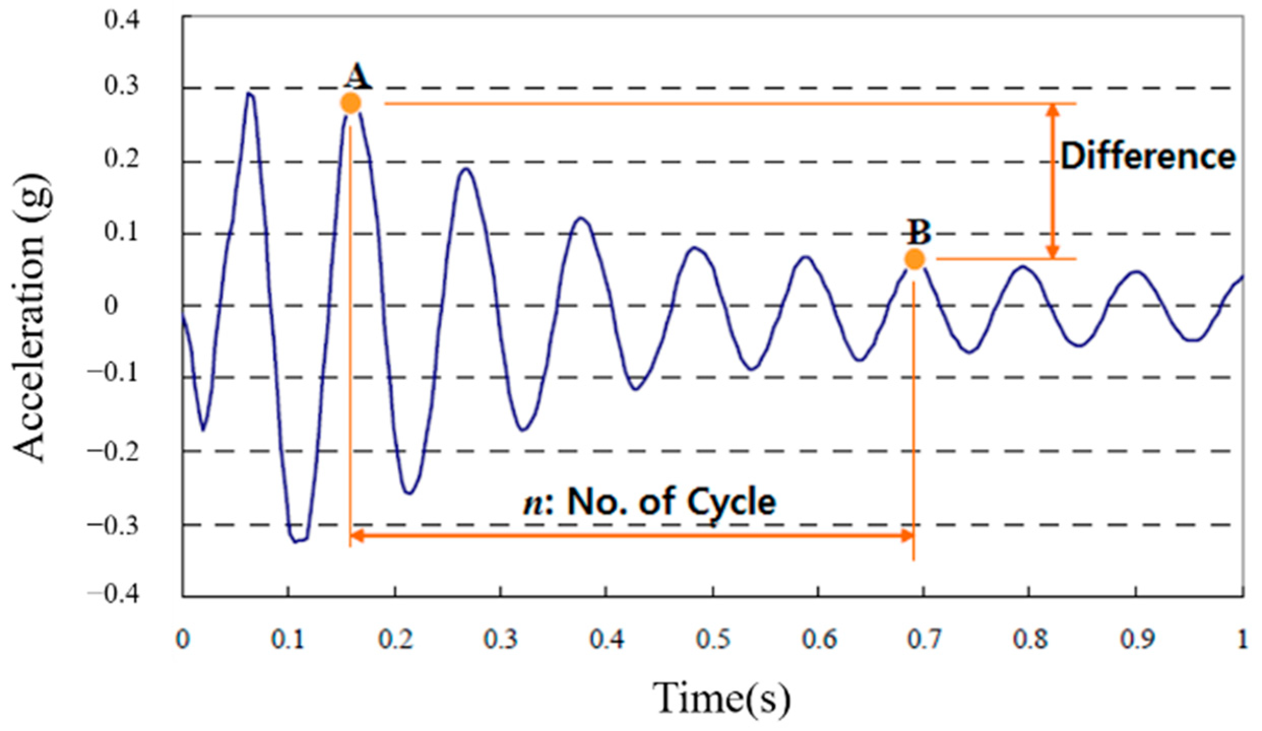
In this study, the logarithmic decrement method was applied to calculate the damping ratio of the system [22]. The logarithmic decrement is a formula that shows the damping ratio of the amplitude of an object; the damping ratio of the amplitude at the point where an n number of cycles had passed was determined by taking the natural logarithm as shown in Formula (1) [17].
ξ = ln ( A / B ) 2 n π
In the formula, A and B are the amplitudes and n is the number of cycles. Figure 3 shows the logarithmic decrement. We used the first mode of the free-vibration time-series waveform in order to estimate the damping ratio [23].

2.2. Vibration Criteria

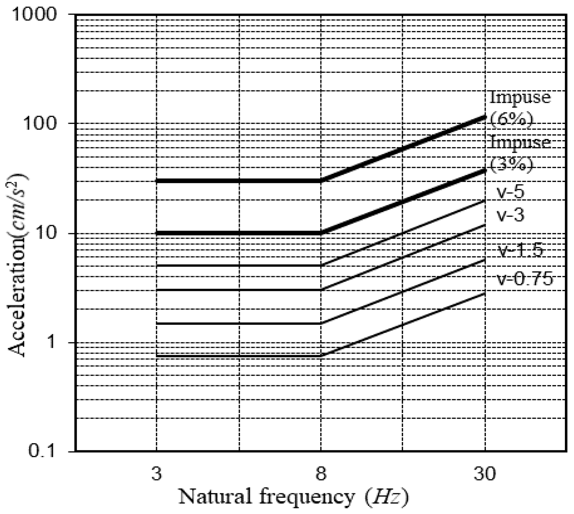
The damping ratio of the floor during the vibration evaluation was considered for the evaluation of habitability based on the building vibration guidelines AIJ, GSA, CSA, and Modified Meister. The vibration criteria can be explained using the AIJ graph shown in Figure 4, and it shows that when the damping ratio of the impulse load increases from 3 to 6%, the allowable acceleration triples within the vibration range from 3 to 30 Hz [11]. Moreover, the CSA criteria [13] (1989) suggested 3, 6, and 12% damping ratios in a similar way that allowed larger criteria vibration values for the walking vibration than continuous vibration on the vibration evaluation curve.

3. Experiment Plan and Method

3.1. Experiment Plan

The impulse load and walking load were selected as the sources of vibration for two different experiments. The natural frequency was analyzed for the walking load, and the damping ratio was analyzed for the heel impulse (impulse load) [24].
In order to analyze the vibration characteristics according to the construction stage (frame completion and cladding completion), this study investigated the effect of the bond of members and finishing materials on the natural frequency and damping ratio at the various construction phases of actual buildings [24].

3.2. Experiment Method

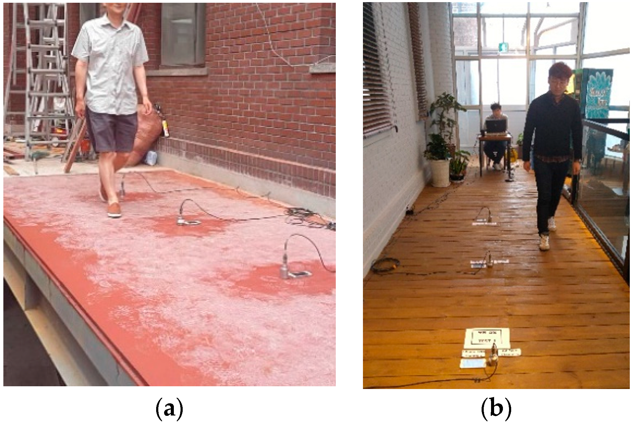
A sensor for measurement was installed at the center of the floor because the response of the floor was the largest at this location [22]. The frame completion is shown in Figure 5a, and the cladding completion is shown in Figure 5b.
In order to investigate the vibration characteristics according to the construction stage, a person weighing 70 kg walked on the floor, 30 cm in the horizontal direction from the sensor, while maintaining a vibration of 2 Hz [25] using a metronome. A heel impulse load was used to measure the damping ratio. The specifications of the equipment [17] used in this study are listed in Table 2.

4. Floor Vibration Experiment

4.1. Nambuk Church

4.1.1. Natural Frequency

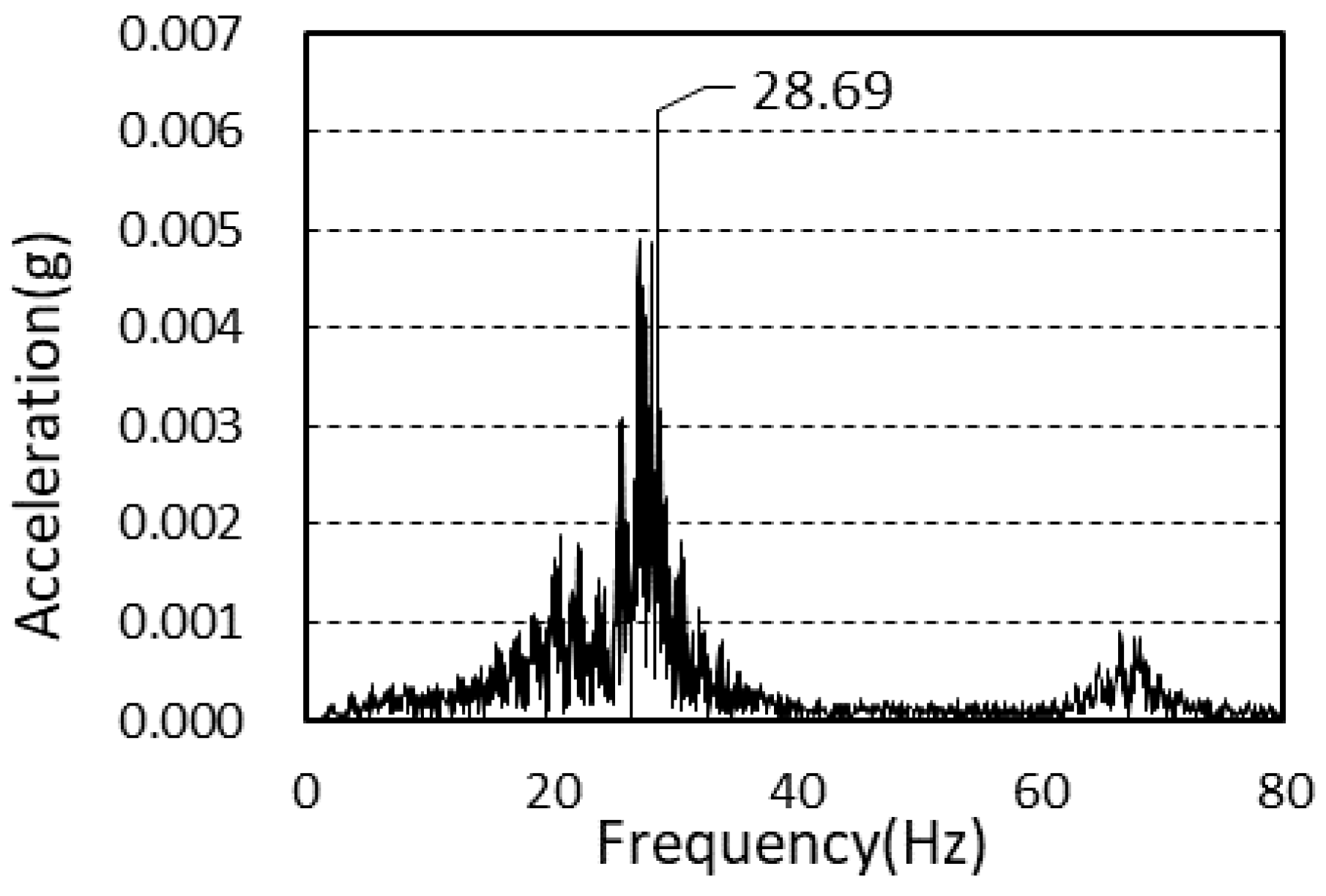
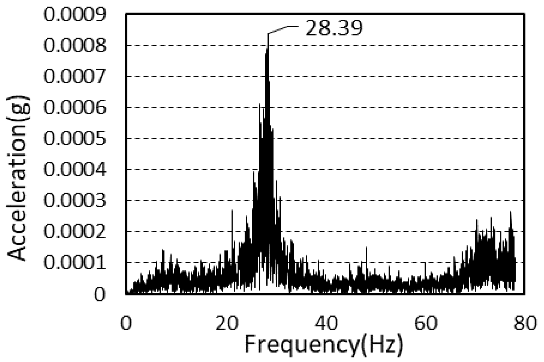
The power spectra of the floor after frame construction completion with the iFLASH system are presented in Table 3. The final values presented here are averages of the values obtained by performing the experiments thrice [23].
The average value of the natural frequency after frame construction completion was 27.6 Hz, and the average value of the natural frequency after cladding completion was 28.5 Hz. There was a difference of 3.26% between the two values.
The natural frequencies according to the construction stage after frame completion and cladding completion are presented in Table 4.
Figure 6 and Figure 7 shows the power spectra after framing completion and cladding completion.

4.1.2. Damping Ratio

To calculate the damping ratio of the floor, the first mode of the free-vibration time-series waveform was used, as shown in Figure 8 and Figure 9.
The values were obtained by performing the experiments thrice. The damping ratios are presented in Table 5.
Considering that the damping ratio of the steel frame floor (which generally utilized the existing deck plate) was between 2 and 5%, it was determined that the iFLASH system had the same damping performance as the existing steel frame.
For the single and assembled members, the damping ratios were 1.26 and 1.17%, respectively [18], and the measured damping ratio after frame completion was 2.63%. After the completion of construction, the damping ratio was 4.57%.

4.2. Sangsoo-Dong Building

4.2.1. Natural Frequency

The experiment for the floor vibration was conducted after frame completion and cladding completion on the second and third floors. All experiments were performed thrice and evaluated using the average values.
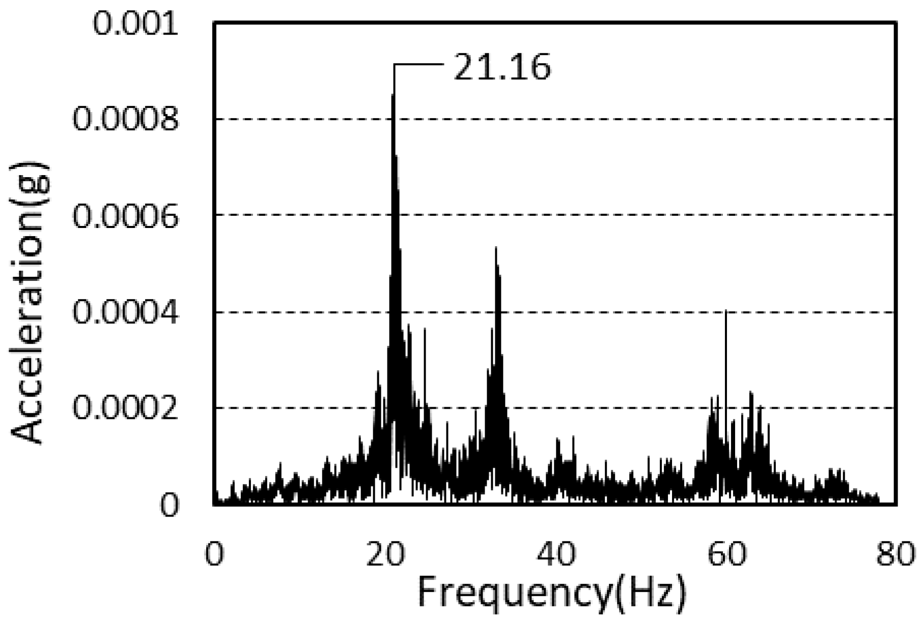
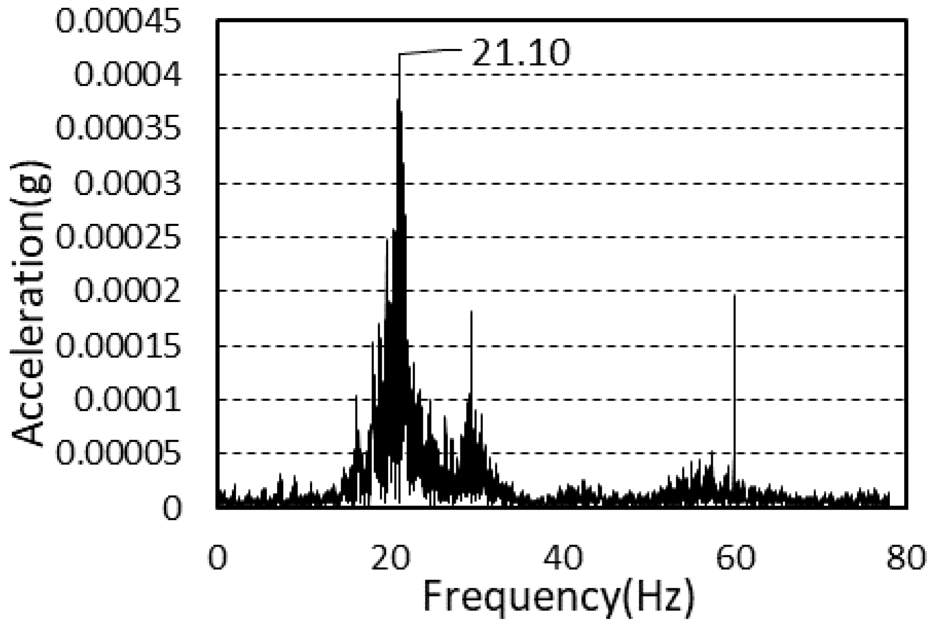
For the power spectrum of the slab for the different construction stages, the final values were obtained from three walking vibration values, as presented in Table 6.
The natural frequencies of the vibration of the second and third floors after framing completion were 21.29 and 24.29 Hz, respectively. The average natural frequencies of the vibration of the second and third floors after cladding completion were 21.23 and 20.01 Hz, respectively.
The power spectra after framing completion and cladding completion are presented in Figure 10 and Figure 11.

4.2.2. Damping Ratio

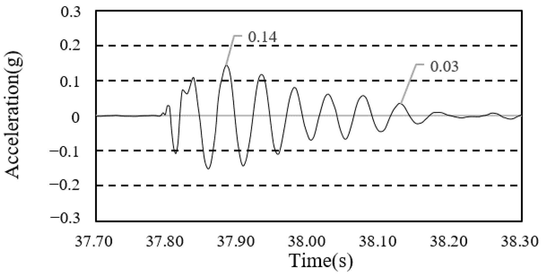
The heel impulse test was conducted in order to obtain a free-vibration damping ratio curve. In order to calculate the damping ratio of each construction phase, the first mode of the free-vibration time-series waveform was used, as shown in Figure 12 and Figure 13. The average values obtained by performing each experiment thrice are presented in Table 7.
The measured damping ratio after framing completion was 3.98%, and that after the completion of cladding was 4.90%. The values confirmed that the Sangsoo-dong site had the same damping performance as the existing deck plate.

5. Serviceability Test

5.1. Maximum Acceleration

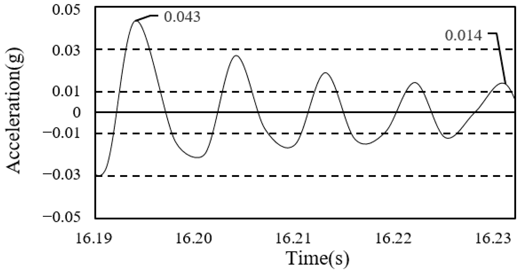
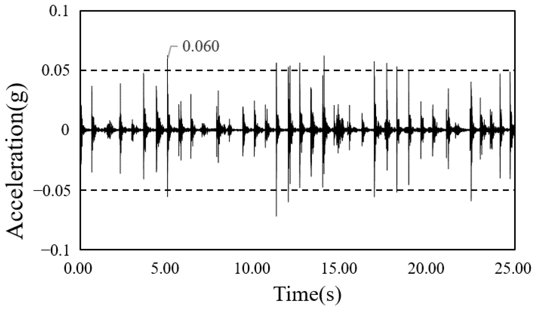
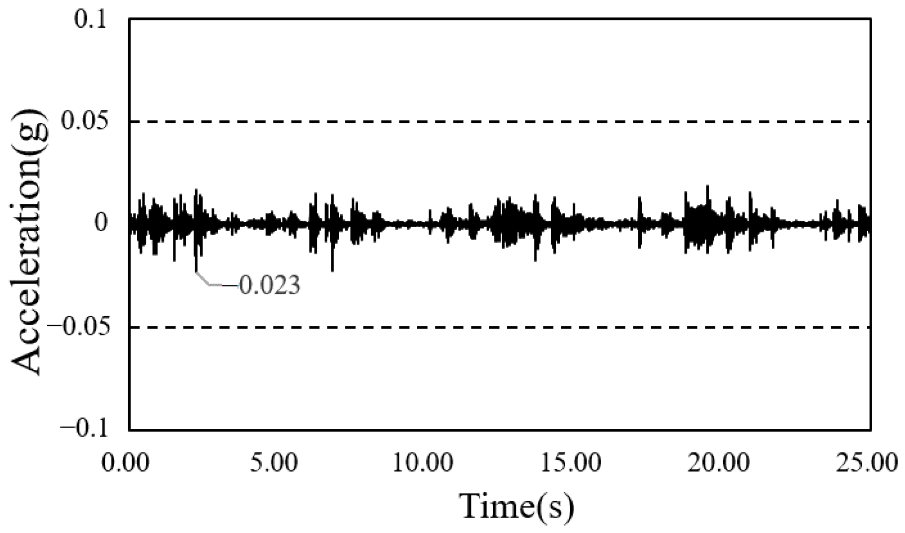
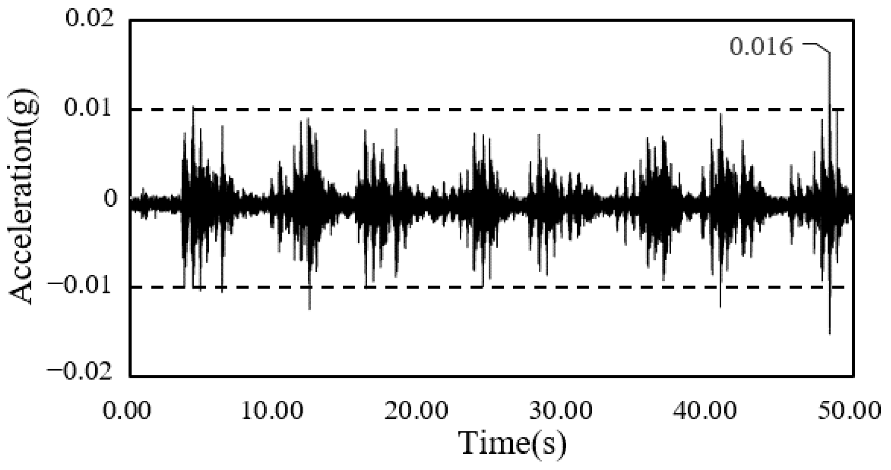
To evaluate the maximum acceleration of the iFLASH system, the acceleration of the floor vibration was measured upon the application of a walking load to it. The experiment was conducted thrice after framing and cladding completion on the second and third floors, and the average values of the maximum acceleration are presented in Table 8 and Table 9.
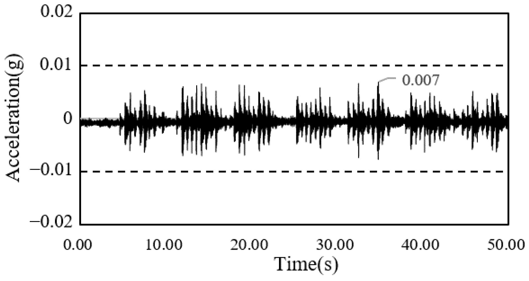
The average maximum acceleration after framing completion for the Sangsoo-dong building was 0.0163 g on the second floor and 0.0170 g on the third floor. The average maximum acceleration after cladding completion was 0.0089 g on the second floor and 0.0089 g on the third floor.
The average maximum acceleration after framing completion for the South-North church was 0.075 g, and the average maximum acceleration of the slab after cladding completion was 0.030 g.
Comparing the measured maximum acceleration results after framing completion and the completion of the construction, the values decreased by approximately 40–60% due to the influence of cladding.
It has been illustrated that non-structural elements can have significant effects on the dynamic responses of the floor systems of buildings; evidence for such effects was observed in determining the dynamic parameters of both slender floor systems [26,27] and traditional concrete floor systems, as detailed [28].
The time-series waveform graphs corresponding to framing completion and the completion of the construction of the South-North church are shown in Figure 14 and Figure 15, and those of the Sangsoo-dong building are shown in Figure 16 and Figure 17.
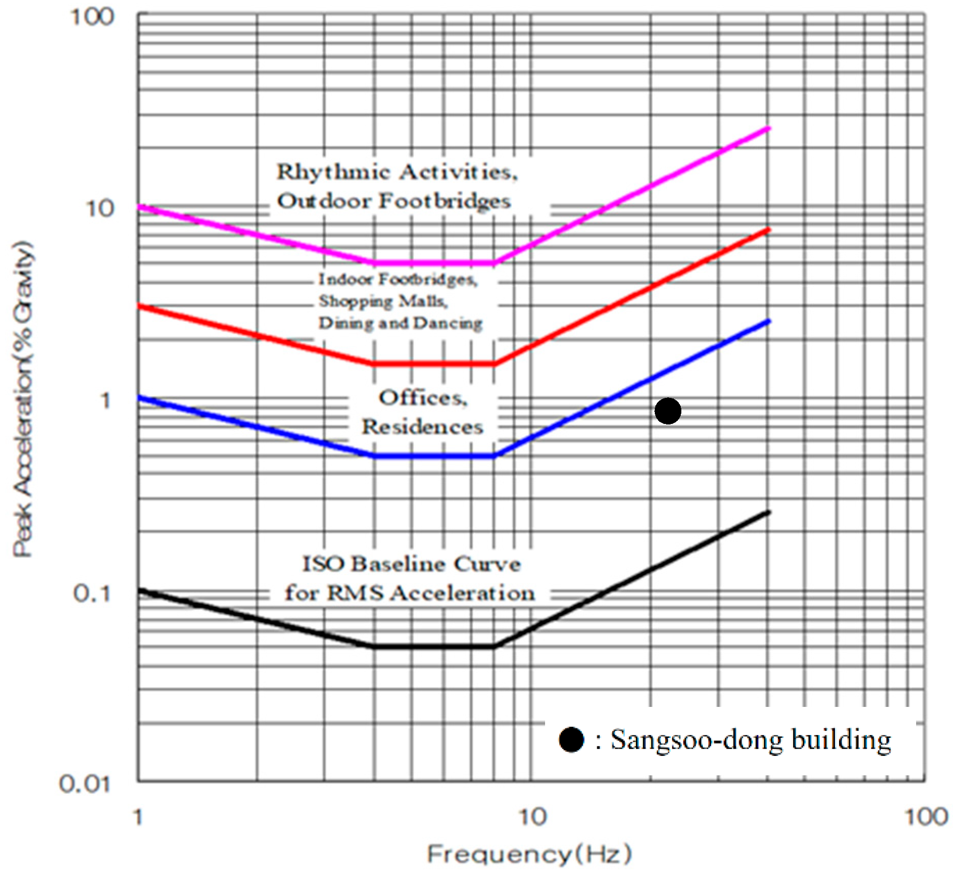
The vibration evaluation of the iFLASH system was conducted using the guidelines for the evaluation of habitability regarding building vibration [11] and the ISO 2631-211 vibration evaluation standard [29].

5.2. Guidelines for the Evaluation of Habitability

The guidelines for the evaluation of habitability [11] for the three categories of vibration are shown in Table 10. The classification of the grades of the allowable vibration range (from V-0.75 to V-30) according to the purpose of the building is shown in Table 11. The walking load was evaluated based on the vibration type 1 (floor affected by continuous or intermittent vibration).
The maximum acceleration in the case of the South-North church was higher than that of the Sangsoo-dong building, which used the same iFLASH system because the three sides of the South-North church were fixed and one side was free due to the installation of stairs (Figure 18). As there was no instruction or criteria for evaluating the vibration of the stairs, the vibrational distribution of the steel frame stairs based on the AIJ vibration criteria was applied (Figure 19).
Figure 20 shows the vibration evaluation curve (based on [11]); the floor vibration is evaluated through the natural frequency and the maximum acceleration of the vibration of the floor. The natural frequency and the maximum acceleration of the iFLASH system were determined based on the experimental results for the two buildings, and the values are presented in Table 12.
For the South-North church, the maximum vibration distribution of the X-marked steel frame stair was similar to the maximum acceleration of the slab of the South-North church.
The result of the vibration evaluation for the Sangsoo-dong building is presented in Figure 20, and it satisfies the V-3 vibration performance standard. Therefore, this system met the Grade II standard with respect to housing and the Grade I standard with respect to offices.

5.3. ISO 2631-2

ISO 2631-2 suggests a floor vibration standard based on the vibration evaluation curve. Similar to the AIJ [11] standard, it evaluates the vibration performance of a building by the natural frequency and maximum acceleration. The natural frequency and maximum acceleration are presented in Table 13.
The result of the vibration evaluation for the Sangsoo-dong building is presented in Figure 20, and it satisfied the Offices & Residences part of the vibration performance standard.

6. Conclusions

In order to investigate the floor vibration characteristics of an iFLASH system, this study performed a floor vibration experiment for walking loads and heel impulses. However, human excitation of the load was used so that the free vibration could be different for each experiment. Thus, according to the serviceability guidelines, one person excited a load as equal as possible. The target buildings where the iFLASH system was applied were the construction site of the South-North church and the new construction site of the Sangsoo-dong building. The iFLASH system was determined to be a new floor system that can effectively play the role of a slab with extremely low thickness and improving constructability, shortening the construction duration, and reducing the self-weight. However, the drawback of the iFLASH system is that it is not commercialized and mass produced at present, so the cost of the materials is high, but the overall construction cost is similar because the installation is simple and it shortens the construction duration. If commercialization and mass production are possible in the future, it is believed that cheaper construction costs will be realized. The system used both bolted joints as well as welding for installation on buildings, and this decreased the construction duration, floor height, and structural weight, owing to the low-thickness and lightweight features. Accordingly, owing to the very low thickness of the system, the floor vibration performance was a point of major concern.
Therefore, floor vibration tests for the iFLASH system in real buildings were conducted to evaluate the vibration performance. However, in this study, the vibration tests were conducted only in commercial facilities; therefore, it is highly recommended for a future study to conduct a vibration test and serviceability test under the same conditions of the iFLASH slab installation for different facilities such as offices, residences, etc. The results are summarized below.
(1) According to the results of the floor vibration experiment at the South-North church construction site, the natural frequency after the completion of the construction was 28.5 Hz, and the damping ratio was 4.57%. For the Sangsoo-dong building, the natural frequency after the completion of the construction was 21.2 Hz, and the damping ratio was 4.90%. Based on the result for a steel frame building with a normal deck plate showing a 2–5% damping ratio, it was found that the iFLASH system had the same damping performance as the existing steel frame.
(2) According to the serviceability test results, the natural frequency was 28.5 Hz, and the maximum acceleration was 0.030 g. As the three sides of the South-North church were fixed and only one side was free because of the stairs installed, its maximum acceleration was greater than that of the Sangsoo-dong building, for the same iFLASH system. As there was no instruction or criteria for the evaluation of the vibration of stairs, the vibrational distribution of the steel frame stairs corresponding to the AIJ vibration criteria was applied with the AIJ guidelines for the evaluation of habitability, and it showed a similar distribution.
(3) For the Sangsoo-dong building, the natural frequency after the completion of construction was 21.2 Hz, and the maximum acceleration was 0.009 g. As this result satisfied the vibration performance criteria of ISO 2631-2 for both offices and residences, the iFLASH system applied in the Sangsoo-dong building can be safely used for current purposes.
Author Contributions

Conceptualization, J.H.L., M.J.P. and S.W.Y.; methodology, S.W.Y.; software, J.H.L.; validation, M.J.P. and S.W.Y.; investigation, J.H.L., M.J.P. and S.W.Y.; data curation, J.H.L.; writing—original draft preparation, J.H.L. and S.W.Y.; writing—review and editing, J.H.L. and S.W.Y.; visualization, J.H.L. and M.J.P.; supervision, S.W.Y.; project administration, S.W.Y.; funding acquisition, S.W.Y. All authors have read and agreed to the published version of the manuscript.

Funding

The authors disclose the receipt of the following financial support for the research, authorship, and publication of this article: This study was supported by the National Research Foundation of Korea, grant NRF-2016R1A2B2014064 and grant NRF-2019R1A2C1086485. The authors are grateful to the authorities for their support.

Conflicts of Interest

The authors declare no conflict of interest.

References

  1. Ryu, J.H.; Ju, Y.K.; Yoon, S.W.; Kim, S.D. Bending capacities of glass fibre reinforced plastic composite slab. Mater. Res. Innov. 2013, 17, 12–18. [Google Scholar] [CrossRef]
  2. Ryu, J.H.; Ju, Y.K.; Yoon, S.W.; Kim, S.D. Bending capacity of glass fibre steel composite plate (GSP) reinforced composite slab. Mater. Res. Innov. 2013, 17, 27–34. [Google Scholar] [CrossRef]
  3. Ryu, J.H.; Lee, C.H.; Oh, J.T.; Yoon, S.W.; Ju, Y.K. Shear Resistance of a Biaxial Hollow Composite Floor System with GFRP Plates. J. Struct. Eng. 2016, 143, 04016180. [Google Scholar] [CrossRef]
  4. Ju, Y.-K.; Kim, S.-D. Behaviour of RC column to iTECH composite beam joint. Proceedings of the Institution of Civil Engineers. Struct. Build. 2005, 158, 97–107. [Google Scholar] [CrossRef]
  5. Kim, S.B.; Le, C.N.; Kim, S.S. Experimental Study on the Flexural Performance of Bottle Neck TSC Beam. J. Arch. Inst. Korea 2006, 22, 11–17. [Google Scholar]
  6. Park, Y.J.; Shin, D.H. Application of Concrete Composite Beam (SMART BEAM). Hanjin Constr. Technol. 2012, 51, 90–99. [Google Scholar]
  7. Naccarato, P.A. Low Floor-to-Floor Heights, Modern Steel Construction; American Institute of Steel Construction: Chicago, IL, USA, 2000. [Google Scholar]
  8. Mullett, D.L. Composite Floor Systems; Illustrated, Reprint; Wiley: Hoboken, NJ, USA, 1998. [Google Scholar]
  9. Intelligent Engineering. Company Profile: Sandwich Plate System; Intelligent Engineering: Buckinghamshire, UK, 2009. [Google Scholar]
  10. Kim, Y.Y.; Ryu, J.H.; Yoon, S.W.; Ju, Y.K. Flexural Behavior of iFLASH System with No Blast Metal Cleaned Steel Plates. J. Korean Soc. Adv. Comp. Strut. 2015, 6, 30–37. [Google Scholar] [CrossRef]
  11. The Architectural Institute of Japan. Guidelines for the Evaluation of Habitability to Building Vibration; AIJ: Tokyo, Japan, 1991; pp. 1–34. [Google Scholar]
  12. GSA. Available online: https://www.gsa.gov/real-estate/design-construction/engineering-and-architecture/facilities-standards-p100-overview (accessed on 16 January 2019).
  13. CSA. Canadian Standard CAN3-S16. 1-M89, Steel Structures for Buildings; Canadian Standard Association: Toronto, ON, Canada, 1989. [Google Scholar]
  14. Murray, T.M. Design to Prevent Floor Vibration. Eng. J. Aisc. 1975, 12, 82–87. [Google Scholar]
  15. Murray, T.M.; Allen, D.E.; Ungar, E.E. Floor Vibration Due to Human Activity Design Guide Series II; AISC: Chicago, IL, USA, 1997. [Google Scholar]
  16. Yoon, S.W. Damping Ratio of Light Gauge Steel-Framed Floors. J. Arch. Inst. Korea 2000, 16, 19–26. [Google Scholar]
  17. Ryu, J.H.; Ju, Y.K.; Yoon, S.W. Dynamic Characteristic of Composite Beam using the Sandwich Plate System. J. Korean Assoc. Spat. Struct. 2014, 14, 65–72. [Google Scholar] [CrossRef]
  18. Ryu, J.H.; Kim, Y.H.; Park, M.W.; Yoon, S.W.; Lee, C.H.; Ju, Y.K. Experimental and numerical investigations of steel-polymer hybrid floor panels subjected to three-point bending. Eng. Struct. 2018, 175, 467–482. [Google Scholar] [CrossRef]
  19. Park, M.J.; Bae, J.; Ryu, J.; Ju, Y.K. Fire resistance of hybrid floor based on small-scale furnace tests and energy-based time equivalent approach. Int. J. Steel Struct. 2020, 20, 1811–1821. [Google Scholar] [CrossRef]
  20. Park, M.J.; Min, J.K.; Bae, J.; Ju, Y.K. Thermal contact conductance-based thermal behavior analytical model for a hybrid floor at elevated temperatures. Materials 2020, 13, 4257. [Google Scholar] [CrossRef] [PubMed]
  21. Park, M.J.; Bae, J.; Ryu, J.; Ju, Y.K. Fire design equation for steel-polymer composite floors in thermal fields via finite element analysis. Materials 2020, 13, 5573. [Google Scholar] [CrossRef] [PubMed]
  22. Chopra, A.K. Dynamics of Structures: Theory and Application to Earthquake Engineering; Prentice-Hall: Englewood Cliffs, NJ, USA, 1995. [Google Scholar]
  23. Lee, J.H.; Lim, D.S.; Ju, Y.K.; Yoon, S.W. Vibration Characteristics of iFLASH System. J. Korean Assoc. Spat. Struct. 2016, 16, 89–98. [Google Scholar] [CrossRef] [Green Version]
  24. Yoon, S.W. Dynamic Characteristic of Post-tensioned Void Slab. J. Korean Assoc. Spat. Struct. 2012, 12, 89–95. [Google Scholar] [CrossRef]
  25. Facility Design. Construction and Maintenance Manuals; Facility Design: Seoul, Korea, 2001. [Google Scholar]
  26. Reynolds, P. The Effects of Raised Access Flooring on the Vibrational Performance of Longspan Concrete Floors. Ph.D. Thesis, University of Sheffield, Sheffield, UK, 2000. [Google Scholar]
  27. Miskovic, Z.; Pavic, A.; Reynolds, P. Effects of full-height nonstructural partitions on modal properties of two nominally identical building floors. Can. J. Civ. Eng. 2009, 36, 1121–1132. [Google Scholar] [CrossRef]
  28. Devin, A.; Fanning, P.J.; Pavic, A. Nonstructural partitions and floor vibration serviceability. J. Archit. Eng. 2016, 22, 04015008. [Google Scholar] [CrossRef] [Green Version]
  29. ISO. Available online: https://www.iso.org/standard/7613.html (accessed on 16 January 2019).
Figure 1. Components of iFLASH system.
Materials 13 05760 g001
Figure 2. Typical and renovation module.
Materials 13 05760 g002
Figure 3. Logarithmic decrement.
Materials 13 05760 g003
Figure 4. Japanese guidelines [11].
Materials 13 05760 g004
Figure 5. Vibration tests (walking loads): (a) Frame completion; (b) Cladding completion.
Materials 13 05760 g005
Figure 6. Power spectrum (framing completion).
Materials 13 05760 g006
Figure 7. Power spectrum (cladding completion).
Materials 13 05760 g007
Figure 8. Damping ratio (framing completion).
Materials 13 05760 g008
Figure 9. Damping ratio (cladding completion).
Materials 13 05760 g009
Figure 10. Power spectrum (framing completion).
Materials 13 05760 g010
Figure 11. Power spectrum (cladding completion).
Materials 13 05760 g011
Figure 12. Damping ratio (framing completion).
Materials 13 05760 g012
Figure 13. Damping ratio (cladding completion).
Materials 13 05760 g013
Figure 14. Time history of acceleration after framing completion (South-North church).
Materials 13 05760 g014
Figure 15. Time history of acceleration after cladding completion (South-North church).
Materials 13 05760 g015
Figure 16. Time history of acceleration after framing completion (Sangsoo-dong building).
Materials 13 05760 g016
Figure 17. Time history of acceleration after cladding completion (Sangsoo-dong building).
Materials 13 05760 g017
Figure 18. Cladding completion in Nambuk Church.
Materials 13 05760 g018
Figure 19. Vibration evaluation curve based on the Architecture Institute of Japan standard [11].
Materials 13 05760 g019
Figure 20. Vibration evaluation curve based on the ISO 2631-2 floor vibration standard [29].
Materials 13 05760 g020
Table 1. Mechanical properties of the nano-composite used in this study.
PropertyValue
Density1178 kg/m3
Tensile strength31.4 MPa
Young’s Modulus in tension1277 MPa
Rupture strain in tension0.295
Compressive strength23.1 MPa
Young’s Modulus in compression461 MPa
Poisson’s ratio0.39
Bond strength with steel plates6.34 MPa
Table 2. Measurement equipment.
EquipmentParameterSpecification
ICPAccelerometer(Dytran 3191A, Dytran, Los Angeles, CA, USA)Capacity±1 g
Output voltage±5 g
Volt sensitivity5000 mV/g
Transversesensitivity4.2%
DynamicChannel4
AnalyzerFilter90 dB
(Signalcalc Mobilyzer)AcquisitionApproximately 5–8 Hz
Metronome(SQ 10–77, Seiko, Tokyo, Japan)Approximately 30–250 times/minApproximately 30–250 times/min
Table 3. Natural frequency.
Construction PhaseNatural Frequency (Hz);
Experimental Value, E
Framing completion27.6
Cladding completion28.5
Table 4. Natural frequencies for different construction phases.
Construction PhaseNatural Frequency (Hz)
1st2nd3rdAverage
Framing completion28.6927.1826.8627.6
Cladding completion28.3928.6328.4128.5
Table 5. Damping ratios of specimens [19].
Construction PhaseDamping Ratio (%)
iFLASH panel1.26
iFLASH composite panel1.17
Framing completion2.63
Cladding completion4.57
Table 6. Natural frequency of the floors for different construction phases.
Construction PhaseNatural Frequency (Hz)
1st2nd3rdAverage
Frame completion2nd floor21.1621.3021.4021.29
3rd floor24.7224.7823.3724.29
Cladding completion2nd floor21.1021.3021.3021.23
3rd floor21.2419.1119.6920.01
Table 7. Damping ratio of specimens.
SpecimensDamping Ratio (%)
Frame completion3.98
Cladding completion4.90
Table 8. Maximum acceleration (Sangsoo-dong building).
Construction PhaseMax Acceleration (g)
1st2nd3rdAvg.
Frame completion2nd floor0.01610.01530.01750.0163
3rd floor0.01730.01690.01670.0170
Cladding completion2nd floor0.00880.00950.00840.0089
3rd floor0.00700.00980.00990.0089
Table 9. Maximum acceleration (South-North church).
Construction PhaseMax Acceleration (g)
1st2nd3rdAvg.
Frame completion0.0600.0790.0870.075
Cladding completion0.0230.0290.0380.030
Table 10. Japanese guidelines [11].
Vibration TypeDetails
1Floor affected by continuous or intermittent vibration
2Floor with low damping characteristics affected by impact vibration, damping ratio under 3%
3Floor with high damping characteristics affected by impact vibration, damping ratio between 3 and 6%
Table 11. Natural frequency and maximum acceleration [11].
Grade According to Building TypeVibration Type 1Vibration Type 2Vibration Type 3
Building PracticabilityGrade IGrade IIGrade IIIGrade IIIGrade III
HousingDining, bedroomV-0.75V-1.5V-3V-5V-10
OfficeMeeting roomV-1.5V-3V-5V-10V-30
General officeV-3V-5Approximately V-5Approximately V-10Approximately V-30
Table 12. Natural frequency and maximum acceleration for the two buildings.
BuildingsNatural Frequency (Hz)Max. Acceleration (cm/s2)
Nambuk Church28.530
Sangsoo-dong21.28.9
Table 13. Natural frequency and maximum acceleration.
Natural Frequency (Hz)Maximum Acceleration (%g)
21.20.9
Publisher’s Note: MDPI stays neutral with regard to jurisdictional claims in published maps and institutional affiliations.